
Related Manuals for Miller Trailblazer 251


Summary of Contents for Miller Trailblazer 251
- Page 1 OM-485 181 594F November 1997 Processes MIG (GMAW) Welding Flux Cored (FCAW) Stick (SMAW) Welding TIG (GTAW) Welding Description Engine Driven Welding Generator Trailblazer 251 Visit our website at www.MillerWelds.com...
- Page 2 – every power source from This Owner’s Manual is designed to help you get the most out of your Miller is backed by the most Miller products. Please take time to read the Safety precautions. They will hassle-free warranty in the business.
-
Page 3: Table Of Contents
TABLE OF CONTENTS SECTION 1 – SAFETY PRECAUTIONS - READ BEFORE USING ......1-1. Symbol Usage . -
Page 5: Section 1 - Safety Precautions - Read Before Using
SECTION 1 – SAFETY PRECAUTIONS - READ BEFORE USING rom _nd_5/97 1-1. Symbol Usage Means Warning! Watch Out! There are possible hazards with this procedure! The possible hazards are shown in the adjoining symbols. This group of symbols means Warning! Watch Out! possible Y Marks a special safety message. -
Page 6: Engine Hazards
WELDING can cause fire or explosion. HOT PARTS can cause severe burns. D Allow cooling period before maintaining. Welding on closed containers, such as tanks, D Wear protective gloves and clothing when drums, or pipes, can cause them to blow up. Sparks working on a hot engine. -
Page 7: Additional Symbols For Installation, Operation, And Maintenance
READ INSTRUCTIONS. stopping engine. D Do not let low voltage and frequency caused by D Use only genuine MILLER replacement parts. low engine speed damage electric motors. D Perform engine maintenance and service D Do not connect 50 or 60 Hertz motors to the 100 Hertz receptacle according to this manual and the engine where applicable. -
Page 8: Principal Safety Standards
H.F. RADIATION can cause interference. ARC WELDING can cause interference. D High-frequency (H.F.) can interfere with radio D Electromagnetic energy can interfere with navigation, safety services, computers, and sensitive electronic equipment such as communications equipment. computers and computer-driven equipment D Have only qualified persons familiar with such as robots. -
Page 9: Section 1 - Consignes De Sécurité - Lire Avant Utilisation
SECTION 1 – CONSIGNES DE SÉCURITÉ – LIRE AVANT UTILISATION rom _nd_fre 5/97 1-1. Signification des symboles Signifie Mise en garde ! Soyez vigilant ! Cette procédure présente des risques de danger ! Ceux-ci sont identifiés par des symboles adjacents aux directives. Ce groupe de symboles signifie Mise en garde ! Soyez vigilant ! Il y a des Y Identifie un message de sécurité... -
Page 10: Dangers Existant En Relation Avec Le Moteur
tous les métaux renfermant ces éléments peuvent dégager des fumées DES PIÈCES CHAUDES peuvent toxiques en cas de soudage. provoquer des brûlures graves. LE SOUDAGE peut provoquer un in- D Prévoir une période de refroidissement avant d’effec- cendie ou une explosion. tuer des travaux d’entretien. -
Page 11: Dangers Supplémentaires En Relation Avec L'installation, Le Fonctionnement Et La Maintenance
D Ne pas laisser tourner le moteur trop lentement sous D Utiliser uniquement des pièces de rechange risque d’endommager le moteur électrique à cause MILLER. d’une tension et d’une fréquence trop faibles. D Effecteur la maintenance et la mise en service D Ne pas brancher de moteur de 50 ou de 60 Hz à... -
Page 12: Principales Normes De Sécurité
LE RAYONNEMENT HAUTE FRÉ- LE SOUDAGE À L’ARC risque de QUENCE (H.F.) risque de provoquer provoquer des interférences. des interférences. D L’énergie électromagnétique risque de provoquer des interférences pour l’équipement électronique D Le rayonnement haute fréquence (H.F.) peut sensible tel que les ordinateurs et l’équipement com- provoquer des interférences avec les équipements mandé... -
Page 13: Section 2 - Definitions
SECTION 2 – DEFINITIONS 2-1. Symbol Definitions Fast Fast/Slow Stop Engine Slow (Idle) (Run, Weld/Power) (Run/Idle) Start Engine Panel/Local Temperature Fuel Check Valve Engine Oil Battery (Engine) Clearance Read Operator’s Engine Amperes Volts Manual MIG (GMAW), Stick (SMAW) TIG (GTAW) Circuit Breaker Wire Alternating Current... -
Page 14: Dimensions, Weights, And Operating Angles
3-2. Dimensions, Weights, And Operating Angles Dimensions Height 31 in (787 mm) Width 18-3/4 in (476 mm) Y Do not exceed operating angles while Depth 46 in (1164 mm) running or engine damage will occur. Y Do not move or operate unit where it 18 in (457 mm) could tip. -
Page 15: Auxiliary Power Curve
3-4. Auxiliary Power Curve The ac auxiliary power curve shows the auxiliary power available in amperes at the receptacles. SA-183 654 3-5. Duty Cycle Duty cycle is the percentage of 10 minutes that unit can weld at rated 100% Duty Cycle at 250 Amperes DC load without overheating. -
Page 16: Volt-Ampere Curves
3-6. Volt-Ampere Curves The volt-ampere curves show the minimum and maximum voltage and amperage output capabilities of A. CC/AC Mode the welding generator. Curves of other settings fall between the curves shown. B. CC/DC Mode C. CV/DC Mode SA-183 653-A / SA-183 652-A / SA-183 651-A OM-485 Page 12... -
Page 17: Section 4 - Installation
SECTION 4 – INSTALLATION 4-1. Installing Welding Generator Generator Base Metal Vehicle Frame Equipment Grounding Terminal Movement Airflow Clearance Grounding Cable Y Do not lift unit from end. 18 in Use #10 AWG or larger insulated (460 mm) copper wire. 18 in Y If unit does not have GFCI re- (460 mm) -
Page 18: Connecting The Battery
4-3. Connecting The Battery Y Connect negative (–) cable last. – Tools Needed: 3/8, 1/2 in Ref. ST-800 394-C / Ref. ST-180 601-F / Ref. S-0756-D 4-4. Connecting To Weld Output Terminals Y Do not connect to CC and CV terminals at the same time. -
Page 19: Selecting Weld Cable Sizes
4-5. Selecting Weld Cable Sizes Total Cable (Copper) Length In Weld Circuit Not Exceeding 150 ft 200 ft 250 ft 300 ft 350 ft 400 ft 100 ft (30 m) Or Less Welding (45 m) (60 m) (70 m) (90 m) (105 m) (120 m) Amperes... -
Page 20: Adjusting Mig Weld Puddle Consistency
4-7. Adjusting MIG Weld Puddle Consistency Y Stop engine. Stabilizer DC-Z factory connected to suit most MIG (Wire Welding) applications. To change MIG weld puddle consis- tency, proceed as follows: Remove lower front panel and side panel. Starting from center of DC-Z, the three leads 79 will be referred to as inner, middle, and outer. -
Page 21: Section 5 - Operating Welding Generator
SECTION 5 – OPERATING WELDING GENERATOR 5-1. Front Panel Controls DC Polarity/AC Switch Use switch to start engine, select speed, and To Stop: turn Engine Control switch to Off stop engine. In Run/Idle position, engine runs position. Use switch to select AC weld output or polarity at idle speed at no load, and weld/power of DC weld output. -
Page 22: Remote Amperage/Voltage Control
5-2. Remote Amperage/Voltage Control Remote 14 Receptacle RC1 Connect optional remote control to RC1 (see Section 4-6). Remote Hand Control (Optional) Remote Foot Control (Optional) In Example: Process = Stick (SMAW) Min = 40 A CC/DC Max = 160 A CC/DC Max (160 A DC) Min (40 A DC) Set Polarity Switch... -
Page 23: Section 6 - Operating Auxiliary Equipment
SECTION 6 – OPERATING AUXILIARY EQUIPMENT 6-1. Auxiliary Power Receptacles And Circuit Breakers Y Use GFCI-protected exten- sion cords. 120 V 15 A AC Duplex Receptacle RC1 240 V 15 A AC Duplex Receptacle RC2 RC1 and RC2 supply 60 Hz single- phase power at weld/power speed. -
Page 24: Section 7 - Maintenance And Troubleshooting
SECTION 7 – MAINTENANCE AND TROUBLESHOOTING 7-1. Routine Maintenance Y Stop engine before maintaining. also Engine Manual Recycle engine maintenance label. Service engine more fluids. often if used in severe conditions. Wipe up spills. Check fluid levels. See Section 4-2. Full 20 h 25 h... -
Page 25: Maintenance Label
50 hours Oil Filter ... . MILLER 065 251, Onan 122-0645 Oil Capacity ..1.5 qt (1.4 L) or 1.75 qt (1.6 L) with filter change Fuel Grade . -
Page 26: Servicing Air Cleaner
7-3. Servicing Air Cleaner Y Stop engine. Y Do not run engine without air cleaner or with dirty element. Wrapper (Foam Element) Wash wrapper with soap and water solution. Allow wrapper to air dry completely. Spread 1 tablespoon SAE 30 oil evenly into wrapper. -
Page 27: Changing Engine Oil, Oil Filter, And Fuel Filter
7-5. Changing Engine Oil, Oil Filter, And Fuel Filter Y Stop engine and let cool. Oil Drain Valve 1/2 ID x 12 in Hose Oil Filter Change engine oil and filter accord- ing to engine manual. Y Close valve and valve cap before adding oil and run- ning engine. -
Page 28: Adjusting Engine Speed
7-6. Adjusting Engine Speed After tuning engine, check engine speeds with a tachometer (see table). If necessary, adjust speeds as follows: ± 2200 100 rpm Start engine and run until warm. Turn A/V control to max. ± 3700 50 rpm Idle Speed Adjustment Throttle Solenoid Mounting Screw... -
Page 29: Overload Protection
7-7. Overload Protection Y Stop engine. Tools Needed: If circuit breaker or fuse continues to open, contact Factory Authorized Service Agent. 3/8 in Circuit Breaker CB1 CB1 protects the 115 volt ac output to Remote 14 receptacle RC1. If CB1 opens, 115 volt ac output to RC1 stops. - Page 30 Trouble Remedy Low weld output. Check control settings. Place Remote Amperage/Voltage switch in Panel position, or move switch to Remote 14 position and connect remote amperage/voltage control to Remote 14 receptacle RC1. Check and clean air cleaner as necessary (see Section 7-3). Check and adjust engine speed (see Section 7-6).
- Page 31 B. Auxiliary Power Trouble Remedy No power output. Reset circuit breakers CB3, CB4, CB5 and/or CB6 (see Section 6-1). Check fuse F1, and replace if necessary (see Section 7-7). Have Factory Authorized Service Agent check brushes, slip rings, and field current control board PC2. Low power output.
-
Page 32: Section 8 - Electrical Diagram
SECTION 8 – ELECTRICAL DIAGRAM SC-188 716 Figure 8-1. Circuit Diagram for Welding Generator OM-485 Page 28... -
Page 33: Section 9 - Auxiliary Power Guidelines
SECTION 9 – AUXILIARY POWER GUIDELINES 9-1. Selecting Equipment Auxiliary Power Receptacles – Neutral Bonded To Frame 3-Prong Plug From Case Grounded Equipment 2-Prong Plug From Double Insulated Equipment Be sure equipment has this symbol and/or wording. aux_pwr 12/96 – Ref. ST-159 730 / ST-800 577 9-2. -
Page 34: Grounding When Supplying Building Systems
9-3. Grounding When Supplying Building Systems Equipment Grounding Terminal Grounding Cable GND/PE Use #10 AWG or larger insulated copper wire. Ground Device Y Ground generator to system earth ground if supplying power to a premises (home, shop, farm) wiring system. Use ground device as stated in electrical codes. - Page 35 9-5. Approximate Power Requirements For Industrial Motors Industrial Motors Rating Starting Watts Running Watts Split Phase 1/8 HP 1/6 HP 1225 1/4 HP 1600 1/3 HP 2100 1/2 HP 3175 Capacitor Start-Induction Run 1/3 HP 2020 1/2 HP 3075 3/4 HP 4500 1400 1 HP...
- Page 36 9-7. Approximate Power Requirements For Contractor Equipment Contractor Rating Starting Watts Running Watts Hand Drill 1/4 in 3/8 in 1/2 in Circular Saw 6-1/2 in 7-1/4 in 8-1/4 in 1400 1400 Table Saw 9 in 4500 1500 10 in 6300 1800 Band Saw 14 in...
- Page 37 9-8. Power Required To Start Motor Motor Start Code AC MOTOR Running Amperage VOLTS AMPS Motor HP CODE Motor Voltage PHASE To find starting amperage: Step 1: Find code and use table to find kVA/HP. If code is not listed, multiply running amperage by six to find starting amperage.
- Page 38 9-10. Typical Connections To Supply Standby Power Power Company Service Meter Main and Branch Overcurrent Protection Double-Pole, Double-Throw Transfer Switch Obtain and install correct switch. Switch rating must be same as or Customer-supplied equipment is required if greater than the branch overcurrent generator is to supply standby power during protection.
- Page 39 9-11. Selecting Extension Cord (Use Shortest Cord Possible) Cord Lengths for 120 Volt Loads Y If unit does not have GFCI receptacles, use GFCI-protected extension cord. Maximum Allowable Cord Length in ft (m) for Conductor Size (AWG)* Current Load (Watts) (Amperes) 350 (106) 225 (68)
-
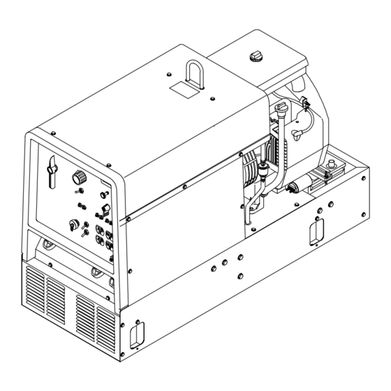
Page 40: Section 10 - Parts List
SECTION 10 – PARTS LIST Hardware is common and not available unless listed. ST-801 613-C Figure 10-1. Main Assembly OM-485 Page 36... - Page 41 Item Dia. Part Mkgs. Description Quantity Figure 10-1. Main Assembly ....182 761 LABEL, general precautionary engine drive ......
- Page 42 Item Dia. Part Mkgs. Description Quantity Figure 10-1. Main Assembly (Continued) ..188 155 CIRCUIT CARD ASSEMBLY, field current controller ....
- Page 43 Item Dia. Part Mkgs. Description Quantity Figure 10-2. Panel, Front w/Components (Fig 10-1 Item 43) ..168 829 TRANSDUCER, current 1000A module max open loop ....
- Page 44 Item Dia. Part Mkgs. Description Quantity Figure 10-3. Generator (Fig 10-1 Item 20) ....182 091 LABEL, warning fuel/fan ......... . .
- Page 47 Effective January 1, 2000 (Equipment with a serial number preface of “LA” or newer) This limited warranty supersedes all previous Miller warranties and is exclusive with no other Warranty Questions? guarantees or warranties expressed or implied. Call LIMITED WARRANTY – Subject to the terms and conditions APT, ZIPCUT &...
-
Page 48: Options And Accessories
Distributor Address City State For Service Call 1-800-4-A-Miller or see our website at www.MillerWelds.com to locate a DISTRIBUTOR or SERVICE AGENCY near you. Always provide Model Name and Serial/Style Number. Contact your Distributor for: Welding Supplies and Consumables Options and Accessories...
Need help?
Do you have a question about the Trailblazer 251 and is the answer not in the manual?
Questions and answers
What is the most likely cause for no power to receptacles on Trailblazer 251?
The most likely cause of no power to receptacles on the Miller Trailblazer 251 is that one or more circuit breakers (CB3, CB4 for RC1; CB5, CB6 for RC2) have opened due to overload. If CB3 or CB4 opens, half of RC1 does not work. If CB5 or CB6 opens, RC2 does not work. Reset the breaker by pressing the button. If the breaker continues to open, contact a Factory Authorized Service Agent.
This answer is automatically generated