Table of Contents
Troubleshooting

Related Manuals for Miller Millermatic 250X


Summary of Contents for Miller Millermatic 250X
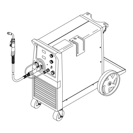
- Page 1 OM-1320 196 846G September 2001 Processes MIG (GMAW) Welding Flux Cored (FCAW) Welding Description Arc Welding Power Source and Wire Feeder Millermatic 250X With Meters And M-25 Gun Visit our website at www.MillerWelds.com...
- Page 2 They had to be the best you could buy. Today, the people that build and sell Miller products continue the tradition. They’re just as committed to providing equipment and service that meets the high standards of quality and value established in 1929.
-
Page 3: Table Of Contents
TABLE OF CONTENTS SECTION 1 – SAFETY PRECAUTIONS - READ BEFORE USING ......1-1. -
Page 5: Section 1 - Safety Precautions - Read Before Using
SECTION 1 – SAFETY PRECAUTIONS - READ BEFORE USING som _nd_4/98 1-1. Symbol Usage Means Warning! Watch Out! There are possible hazards with this procedure! The possible hazards are shown in the adjoining symbols. This group of symbols means Warning! Watch Out! possible Y Marks a special safety message. - Page 6 ARC RAYS can burn eyes and skin. BUILDUP OF GAS can injure or kill. D Shut off shielding gas supply when not in use. Arc rays from the welding process produce intense D Always ventilate confined spaces or use visible and invisible (ultraviolet and infrared) rays that can burn eyes and skin.
-
Page 7: Additional Symbols For Installation, Operation, And Maintenance
1-3. Additional Symbols For Installation, Operation, And Maintenance FIRE OR EXPLOSION hazard. MOVING PARTS can cause injury. D Do not install or place unit on, over, or near D Keep away from moving parts such as fans. combustible surfaces. D Keep all doors, panels, covers, and guards D Do not install unit near flammables. -
Page 8: Emf Information
1-5. EMF Information Considerations About Welding And The Effects Of Low Frequency 1. Keep cables close together by twisting or taping them. Electric And Magnetic Fields 2. Arrange cables to one side and away from the operator. Welding current, as it flows through welding cables, will cause electro- magnetic fields. -
Page 9: Section 1 - Consignes De Securite - Lire Avant Utilisation
SECTION 1 – CONSIGNES DE SECURITE – LIRE AVANT UTILISATION som _nd_fre 4/98 1-1. Signification des symboles Signifie Mise en garde ! Soyez vigilant ! Cette procédure présente des risques de danger ! Ceux-ci sont identifiés par des symboles adjacents aux directives. Ce groupe de symboles signifie Mise en garde ! Soyez vigilant ! Il y a des Y Identifie un message de sécurité... - Page 10 LES RAYONS DE L’ARC peuvent pro- LES ACCUMULATIONS DE GAZ ris- voquer des brûlures dans les yeux et quent de provoquer des blessures ou sur la peau. même la mort. Le rayonnement de l’arc du procédé de soudage D Fermer l’alimentation du gaz protecteur en cas de génère des rayons visibles et invisibles intenses non utilisation.
-
Page 11: Dangers Supplémentaires En Relation Avec L'installation, Le Fonctionnement Et La Maintenance
1-3. Dangers supplémentaires en relation avec l’installation, le fonctionnement et la maintenance Risque D’INCENDIE OU DES ORGANES MOBILES peuvent D’EXPLOSION. provoquer des blessures. D Ne pas placer l’appareil sur, au-dessus ou à proxi- D Rester à l’écart des organes mobiles comme le mité... -
Page 12: Principales Normes De Sécurité
1-4. Principales normes de sécurité Safety in Welding and Cutting, norme ANSI Z49.1, de l’American Wel- Safe Handling of Compressed Gases in Cylinders, CGA Pamphlet P-1, ding Society, 550 N.W. Lejeune Rd, Miami FL 33126 de la Compressed Gas Association, 1235 Jefferson Davis Highway, Suite 501, Arlington, VA 22202. -
Page 13: Section 2 - Installation
SECTION 2 – INSTALLATION 2-1. Specifications Max. Open- Amps Input at Rated Output, 50 or 60 Hz, Single-Phase Rated Output Circuit 200 (208) V 230 V 400 V 460 V 575 V Voltage 250 A at 28 VDC, 200 A at 28 VDC, 40% Duty Cycle 60% Duty Cycle 2.3*... -
Page 14: Welding Gun Duty Cycle And Overheating
2-3. Welding Gun Duty Cycle And Overheating CAUTION WELDING LONGER THAN RATED DUTY CYCLE can damage gun and void warranty. Do not weld at rated load longer than shown below. Using gasless flux cored wire reduces gun duty cycle. warn7.1 8/93 Definition .023 To .045 in (0.6 To 1.1 mm) .023 To .045 in (0.6 To 1.1 mm) Hard Or Flux Cored Wires... -
Page 15: Installing Work Clamp
2-5. Installing Work Clamp Work Cable Boot Slide boot onto work cable. Route cable out front panel opening from inside. Negative (–) Output Terminal Connect cable to terminal and cover connection with boot. Hardware Work Clamp Route cable through clamp handle and secure as shown. -
Page 16: Setting Gun Polarity For Wire Type
2-8. Setting Gun Polarity For Wire Type Polarity Changeover Label Changing Polarity Information Always read and follow manufac- ture’s recommended polarity. Wire Drive Work Clamp Lead Assembly Lead Positive Terminal Negative Terminal Shown as shipped – Electrode Positive (DCEP): For solid steel, stainless steel, aluminum, or flux core with gas wires (GMAW). -
Page 17: Installing Wire Spool And Adjusting Hub Tension
2-10. Installing Wire Spool and Adjusting Hub Tension Use compression spring with 8 in (200 mm) spools. When a slight force is needed to turn spool, tension is set. Tools Needed: 15/16 in ST-072573-B 2-11. Positioning Jumper Links Check input voltage available at site. -
Page 18: Electrical Service Guide
2-12. Electrical Service Guide Input Voltage Input Amperes At Rated Output Max Recommended Standard Fuse Or Circuit Breaker Rating In Amperes Circuit Breaker , Time-Delay Normal Operating Min Input Conductor Size In AWG/Kcmil Max Recommended Input Conductor Length In Feet (Meters) (29) (39) (47) -
Page 19: Threading Welding Wire
2-14. Threading Welding Wire Wire Spool Welding Wire Inlet Wire Guide Pressure Adjustment Knob Drive Roll Outlet Wire Guide Gun Conduit Cable Lay gun cable out straight. Tools Needed: Hold wire tightly to keep it from unraveling. 6 in (150 mm) Open pressure assembly. -
Page 20: Weld Parameter
2-15. Weld Parameter Selecting Wire, Gas and Control Settings What Material Suggested Suggested Wire Sizes Wire Types Shielding Gases are You Welding? (Diameter) and Flow Rate .023” (0.6 mm) Steel Solid (or hard) 100% CO , 20 cfh ER70S–6 .030” (0.8 mm) .035”... - Page 21 Select Voltage and Wire To read settings: Number on left of slash is voltage, number Speed Based on Thickness on right of slash is wire–speed. of Metal Being Welded “—“ Means not recommended. 19.2/398 = Example: VOLTAGE WIRE SPEED 3/8” 1/4”...
-
Page 22: Using Gun/Cable Holder
2-16. Using Gun/Cable Holder Side Panel Latch Cable Holder Press latch down to release and open door. Holster (2) Wrap cable around cable holder, and place gun nozzle into holster. Ref. 802 726-A OM-1320 Page 18... -
Page 23: Section 3 - Operation
SECTION 3 – OPERATION 3-1. Controls Voltage Control Turn control clockwise to increase voltage. Wire Speed Control Turn control clockwise to increase wire feed speed. Power Switch Voltmeter Wire Feed Speed Meter 196 672 OM-1320 Page 19... -
Page 24: Voltmeter And Wire Feed Speed Meter Operation
3-2. Voltmeter And Wire Feed Speed Meter Operation Voltmeter Wire Feed Speed Meter Power Up Status Both meters display zeros at unit power up. After one second, preset values appear on both meters. The MIG gun settings (not spool gun) are always the default at initial power up of the unit. -
Page 25: Section 4 - Maintenance &Troubleshooting
SECTION 4 – MAINTENANCE &TROUBLESHOOTING 4-1. Routine Maintenance Maintain more often Y Disconnect power during severe conditions. before maintaining. 3 Months Replace unreadable labels Repair or replace cracked weld cable Clean and tighten weld terminals 6 Months Remove drive roll and Blow out or vacuum inside. -
Page 26: Replacing Gun Contact Tip
4-4. Replacing Gun Contact Tip Y Turn Off power. Nozzle Contact Tip Cut off welding wire at contact tip. Remove nozzle. Remove contact tip and install new contact tip. Reinstall nozzle. Tools Needed: Ref. 800 797-C 4-5. Changing Drive Roll and Wire Inlet Guide Securing Screw Inlet Wire Guide Loosen screw. -
Page 27: Aligning Drive Rolls And Wire Guide
4-6. Aligning Drive Rolls and Wire Guide Y Turn Off power. View is from top of drive rolls look- ing down with pressure assembly open. Drive Roll Securing Nut Correct Incorrect Drive Roll Wire Guide Welding Wire Drive Gear Insert screwdriver, and turn screw in or out until drive roll groove lines up with wire guide. -
Page 28: Cleaning Or Replacing Gun Liner
4-7. Cleaning Or Replacing Gun Liner Tools Needed: Y Disconnect gun from unit first. 5/16 in, 10 mm Head Tube Remove nozzle, contact tip, and adapter. 5/16 in 10 mm Remove liner. Lay gun cable out straight before installing new liner. To Reassemble Gun: Blow out gun casing. -
Page 29: Replacing Switch And/Or Head Tube
4-8. Replacing Switch And/Or Head Tube Y Disconnect gun first. Remove handle locking nut. Slide handle. Remove switch housing. Note: If installing new switch, push switch lead connectors onto terminal of new switch (polarity is not important). Install switch back into handle, and secure with handle locking nut. If replacing head tube, continue to end of figure. -
Page 30: Troubleshooting
4-9. Troubleshooting Trouble Remedy Be sure line disconnect switch is On (see Section 2-13). No weld output; wire does not feed. Replace building line fuse or reset circuit breaker if open (see Section 2-13). Reset circuit breaker CB1 (see Section 4-2). Secure gun trigger connections (see Section 2-6). -
Page 31: Section 5 - Electrical Diagram
SECTION 5 – ELECTRICAL DIAGRAM 197 699-D Figure 5-1. Circuit Diagram OM-1320 Page 27... -
Page 32: Section 6 - Parts List
SECTION 6 – PARTS LIST Hardware is common and not available unless listed. 802 059-D Figure 6-1. Main Assembly OM–1320 Page 28... - Page 33 . . . LABEL, Miller Millermatic ..........
- Page 34 Hardware is common and not available unless listed. 802 060-C Figure 6-2. Baffle, Center w/Components OM–1320 Page 30...
- Page 35 Item Dia. Part Mkgs. Description Quantity Figure 6-2. Baffle, Center w/Components (Fig 6-1 Item 1) ....058 427 . . . RING, retaining spool ..........
- Page 36 Ref. 800 792-B Figure 6-3. M-25 Gun OM–1320 Page 32...
- Page 37 Item Part Description Quantity Figure 6-3. M-25 Gun (Fig 6-1 Item 16 ) ..200 258 NOZZLE, slip type .500 orf flush ..........
- Page 38 Item Dia. Part Mkgs. Description Quantity Figure 6-4. Panel, Front w/Components (Fig 6-1 Item 15) ....+196 798 PANEL, front control ..........
- Page 39 Item Dia. Part Mkgs. Description Quantity Figure 6-5. Wire Drive And Gears (Fig 6-2 Item 26) ....602 009 . . . SCREW, .250-20 x 1.25 soc hd gr 8 .
- Page 40 Table 6-1. Drive Roll And Wire Guide Kits Note Base selection of drive rolls upon the following recommended usages: V-Grooved rolls for hard wire. U-Grooved rolls for soft and soft shelled cored wires. U-Cogged rolls for extremely soft shelled wires (usually hard surfacing types). V-Knurled rolls for hard shelled cored wires.
- Page 41 Notes...
- Page 42 Notes...
- Page 43 Effective January 1, 2000 (Equipment with a serial number preface of “LA” or newer) This limited warranty supersedes all previous Miller warranties and is exclusive with no other Warranty Questions? guarantees or warranties expressed or implied. Call LIMITED WARRANTY – Subject to the terms and conditions APT, ZIPCUT &...
- Page 44 Distributor Address City State For Service Call 1-800-4-A-Miller or see our website at www.MillerWelds.com to locate a DISTRIBUTOR or SERVICE AGENCY near you. Always provide Model Name and Serial/Style Number. Contact your Distributor for: Welding Supplies and Consumables Options and Accessories...
Need help?
Do you have a question about the Millermatic 250X and is the answer not in the manual?
Questions and answers