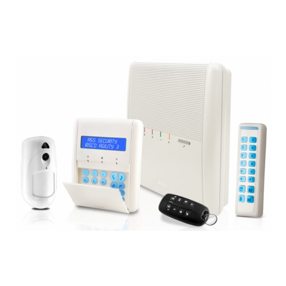
Risco Agility 3 Installer Manual
Hide thumbs
Also See for Agility 3:
- Installer manual (173 pages) ,
- User manual (60 pages) ,
- Quick installation manual (21 pages)
Table of Contents
Advertisement
Quick Links
Advertisement
Table of Contents

Related Manuals for Risco Agility 3


Summary of Contents for Risco Agility 3
- Page 1 Installer Manual...
- Page 2 Corporate and individual names and data used in examples herein belong to their respective owners. Compliance Statement Hereby, RISCO Group declares that the Agility 3 series of central units and accessories are designed to comply with: EN50131-1, EN50131-3 Grade 2...
-
Page 3: Table Of Contents
Video Verification with IP Camera ................. 11 Snapshot Follow Event .................... 11 ..................12 ECHNICAL PECIFICATIONS ................13 MPORTANT AFETY RECAUTIONS CHAPTER 2 INSTALLING THE AGILITY 3 ............14 ..................14 GILITY OMPONENTS .............. 15 ESCRIBING THE OMMUNICATION ODULES PSTN .......................... 15 GSM/GPRS ....................... - Page 4 Step 2: Defining the (GPRS or IP) Communication Channel ............44 Connecting with GPRS .......................44 Connecting with IP ........................44 Step 3: Defining Cloud Parameters for IP or GSM/GPRS ............45 Step 4: Registering to the RISCO Cloud ..................46 ............................46 RISCO A ..........................47...
- Page 5 Agility 3 Installer Manual 2.2.2 Remote Controls ......................84 2.2.3 Keypads ..........................86 2.2.4 Sirens ..........................88 2.2.5 Wireless I/O Expander ....................90 2.3 Identification ..........................98 2.4 Delete .............................98 3. Programming: Codes Menu .......................99 3.1 User ............................99 3.2 Grand Master ........................100 3.3 Installer ..........................100 3.4 Sub-Installer ........................100...
-
Page 6: Chapter 1 Introduction
Installing and Servicing the Agility3 System The Agility 3 system is intended to be installed and serviced only by an alarm system installer (or similar professional, such as electrician). The system is not intended to be installed or serviced by the user / customer. -
Page 7: Key Features
2-way listen-in and talk with VOX Supports 2-way wireless curtain detectors Supports magnetic door/contact detectors with shutter Supports video verification with IP cameras Supports Snapshot Follow Event The following diagram provides an overview of the Agility 3's capabilities: Page 7... -
Page 8: Main Features
Agility 3 Installer Manual Main Features Detectors Monitoring Station Communication Installer Programming • 32 Wireless zones: • Remote programming, • Flexible communication • Local /Remote using • 4 Wired zones via diagnostics and over GSM/GPRS, IP or Configuration Software optional Wireless I/O communication test. -
Page 9: Agility 3 Architecture
Agility 3 Installer Manual Agility 3 Architecture Traditional Agility 3 can communicate information to monitoring stations (and Follow Me destinations) through various communication channels, depending on the physical communication modules installed inside the main panel. Communication can be established through PSTN, IP, or GSM/GPRS. -
Page 10: Cloud Communication
Agility 3 Installer Manual Cloud Communication Agility 3 can be constantly connected to a dedicated application server (the “RISCO Cloud”) via IP or GPRS. The RISCO Cloud handles all communication between the Agility3 system, monitoring stations and Smartphone/Web users, enabling remote monitoring and control, as well as a RISCO’s VUpoint video verification solution that utilizes IP cameras:... -
Page 11: Video Verification With Ip Camera
Powered by the RISCO Cloud, VUpoint enables the initiation of live video streaming on demand from any IP camera which can be viewed directly using the iRISCO smartphone or Web applications. -
Page 12: Technical Specifications
Agility 3 Installer Manual Technical Specifications The following technical specifications are applicable for the Agility 3: Electrical Characteristics Power 230 VAC (-15%+10%), 50 Hz, 50 mA Main board: Typically 130 mA GSM: Standby 35 mA, Communication 300 mA Units consumptions... -
Page 13: Important Safety Precautions
Agility 3 Installer Manual Important Safety Precautions WARNING: Installation or usage of this product that is not in accordance with the intended use as defined by the supplier and as described in the instructional materials can result in damage, injury or death. -
Page 14: Chapter 2 Installing The Agility 3
Agility 3 Installer Manual Chapter 2 Installing the Agility 3 Agility 3 Main Components The illustration below shows the internal components when the main panel’s mounting bracket (back cover) is detached from the main panel housing. Main Panel Bracket –... -
Page 15: Describing The Communication Modules
Describing the Communication Modules PSTN The Agility 3’s PSTN modem is an easy-to-add plug-in module that enables a typically inexpensive PSTN connection, for use as either the primary communication channel or as a failure back-up channel to Cloud communication via GSM/GPRS or IP. The modem enables the panel to communicate with a monitoring station using common format protocols (SIA, Contact ID). -
Page 16: Gsm/Gprs
(in parallel to the Cloud-based notifications), depending on system configuration. Reporting events to monitoring stations is via GPRS, voice, or SMS (using the RISCO IP Receiver). Events can be reported in SIA, SIA IP, and Contact ID monitoring protocols. The GSM/GPRS module also supports two-way voice communication between users and the monitoring station, which can be beneficial for elderly care, especially in times of emergency. -
Page 17: Installing The Pstn Module
Agility 3 Installer Manual Installing the PSTN Module Page 17... -
Page 18: Installing The Gsm/Gprs Module
Agility 3 Installer Manual Installing the GSM/GPRS Module Page 18... -
Page 19: Installing The Ip Module
Agility 3 Installer Manual Installing the IP Module Page 19... -
Page 20: Installing The Main Panel
Installing the Main Panel IMPORTANT: Only alarm system installers or similar professionals (such as electricians) should install and service the Agility 3 system. Choosing the Mounting Location Before you mount the main panel, study the premises carefully in order to choose the best exact location. - Page 21 Agility 3 Installer Manual Figure 1: Mounting Bracket screws Gently, pull up the mounting bracket to a 45° angle and slide it down to release the mounting bracket (Figure 2, detail 2) from the two locking tabs (Figure 2, detail 1) at the top of the unit.
- Page 22 Agility 3 Installer Manual Anchor cables with dedicated hooks (see Figure 3, detail 4). Configuration A Configuration B Figure 3: Wall Installation Adjust the tamper switch (using a small flathead screwdriver) according to your preferred configuration: Box and Wall configuration (see Figure 3, detail 6) - Triggers the tamper when the box (main panel) or the wall mounting are tampered with.
-
Page 23: Installing The Backup Battery
Agility 3 Installer Manual Installing the Backup Battery Agility 3 has a safety approved, sealed lead acid 6V, 3.2 Ah rechargeable backup battery for use in case of a power failure: WARNING: Risk of explosion exists if battery is replaced by an incorrect type. -
Page 24: Connecting To The Power Supply - Configuration A
Agility 3 Installer Manual Connecting to the Power Supply - Configuration A For this configuration, the Agility 3 main panel is permanently connected to the mains via wall power supply or circuit breaker. The connection must be made in compliance with applicable electrical code and regulations. -
Page 25: Grounding Guidelines
It may be possible to use an existing electrical ground on the premises if one is close enough to the Agility 3. When connecting the ground wire, use a solid 14-gauge wire [or larger (numerically lower) size]. Keep this wire as short as possible and do not run it in conduit, coil it, bend it sharply, or run it alongside other wiring. -
Page 26: Connecting To The Power Supply - Configuration B
Agility 3 Installer Manual Connecting to the Power Supply – Configuration B In this configuration, the Agility 3 main panel is powered via a 9 VDC / 1.0 A transformer. Connect the transformer plug into the DC socket located on the bracket module (PCB). -
Page 27: Dip Switch Settings
DIP Switch 2 (E-A): External Audio: Used to define if the audio from the system will be heard from the control panel or from an external audio unit. If an external unit is connected to the Agility 3 system, the audio will be heard only through the external audio unit. - Page 28 Agility 3 Installer Manual DIP Switch 4 (PRGM): Enables loading local software updates to the Agility 3 ON: software updates to the Agility 3 can be loaded OFF (Default): software updates to the Agility 3 cannot be loaded DIP Switch 5 (BAT): Defines the Battery Discharge Protection option settings...
-
Page 29: Connecting To A Telephone Line
Agility 3 Installer Manual Connecting to a Telephone Line Connect the system to a telephone line if the system configuration includes an internal modem (identical for configuration A and B). Connect the incoming telephone line to the LINE terminal. Connect a telephone on the premises to the SET terminal. -
Page 30: Connecting A Network Cable
Figure 7: Network Cable Wiring Installing the SIM Card If your Agility 3 system is equipped with a GSM/GPRS module, insert a SIM card in order to enable GSM/GPRS communication. CAUTION: Do not install SIM card while the main panel is powered up. -
Page 31: Disabling A Sim Pin
Agility 3 Installer Manual Insert the SIM into the dedicated SIM card slot located on the rear side of the back panel. SIM Card 2. Open the SIM card 1. Slide down SIM 3. Close the SIM card card hatch . -
Page 32: Gsm Module Led Indications
Agility 3 Installer Manual GSM Module LED Indications GMS Module LEDs PWR LED: On=power on, off= no power NOTE: After powering up the GSM module with the SIM card installed, the module performs an automatic test of the GSM signal (RSSI) level. -
Page 33: External Audio Unit Installation
Agility 3 Installer Manual External Audio Unit Installation The system can be connected to a remote external audio unit to be used instead of the main panel’s internal speaker for listening to the system's audio messages. In addition, the external audio unit enables you to talk to your protected premises. -
Page 34: Chapter 3 Installer Programming
Chapter 3 Installer Programming Programming Methods The following options are available for the installer to program the Agility 3 system: NOTE: The Agility 3 can be programmed only using one keypad at a time. Temporary “ Installer” LCD Keypad (typically used for example, if customer’s kit doesn’t include an LCD keypad) -
Page 35: Allocating The Customer's Lcd Keypad & Setting The Default Language
See Wireless Device Allocation, page 38. Allocating the Customer’s LCD Keypad & Setting the Default Language Agility 3 can be fully configured via the customer’s wireless LCD keypad. New systems require that the LCD keypad be the first device to be allocated to the system, from which it then prompts the installer to define a default language. -
Page 36: Configuration Software
Working at a remote site, communicating with the system via a phone line, modem or IP address. For further information on programming the Agility 3 system via the Configuration software, refer to the Configuration Software manual. Storing and Transferring System Configuration Data via PTM The PTM is a tiny circuit board into which the main panel can transmit a copy of the system's configuration. - Page 37 Agility 3 Installer Manual To transfer the system configuration from the PTM to the main panel: Disconnect the flat cable and remove the Agility 3 panel from its wall bracket. NOTE: Make sure the battery is inserted into the main panel.
-
Page 38: Wireless Device Allocation
Agility 3 Installer Manual Wireless Device Allocation All wireless devices (detectors and accessories) must also be allocated (registered) to the system. Allocations can be performed via: Main panel: Quick allocation of all devices is performed by sending a RF signal transmission from each device. -
Page 39: Table Of Device Transmissions
Agility 3 Installer Manual Table of Device Transmissions Wireless device Transmission procedure 2-Way LCD Keypad Press simultaneously for at least 2 seconds 2-Way Slim Keypad Press simultaneously for at least 2 seconds. PIR Detectors: • PIR • PIR camera • PIR-pet Press the tamper switch for 3 seconds. -
Page 40: Device Allocation Using The Wireless Lcd Keypad
Agility 3 Installer Manual Device Allocation using the Wireless LCD Keypad RF Allocation Method Using the RF Allocation method, zones are assigned automatically and sequentially. To perform device allocation by RF Allocation: Go to the Installer menu and select Programming... -
Page 41: Zone Allocation Method
Agility 3 Installer Manual Zone Allocation Method When performing allocation by the Zone Allocation method, you manually select a specific zone / index number to which the device is then allocated. To allocate devices with zones manually-specified: From the Installer menus select: Programming > Radio Device > Allocation >... - Page 42 Agility 3 Installer Manual The main panel will acknowledge the transmission with a sound. When the system recognizes the device the Radio Device Allocation screen indicates that the status of allocation has been successful. The serial number, accessory type and the index number information will be displayed.
-
Page 43: Deleting Devices
Agility 3 Installer Manual Deleting Devices Deleting wireless device allocations can be done from the LCD keypad or from the Configuration Software. Deleting can be done for all devices simultaneously, or for a single device. Deleting all Devices Simultaneously from the LCD Keypad... -
Page 44: Deleting A Single Device From The Configuration Software
Delete button. Establishing Communication to the RISCO Cloud Agility 3 can be configured to be constantly connected to the RISCO Cloud, an application server that handles all communication between the system, service providers and Smartphone/Web users. The Cloud enables remote monitoring and control of the system, sending event notifications, and viewing real-time video clips via VUpoint IP cameras –... -
Page 45: Step 3: Defining Cloud Parameters For Ip Or Gsm/Gprs
NOTE: The SIM card must be installed (see Installing the SIM Card, page 30). Controls: The Agility 3 supports parallel channel reporting (via PSTN, IP, GPRS SMS, or voice) to both the monitoring station and Follow Me users. Use this setting to... -
Page 46: Step 4: Registering To The Risco Cloud
Once the self registration is complete, users can enjoy the iRISCO Smartphone app for smart and easy control of their Agility 3 system from any location. The next step is to download the iRISCO app from the Apple App store or Android Play Store. -
Page 47: Pir Camera Setup
PIR Camera Setup PIR-based camera detectors perform detection with advanced still image and video recording capabilities. Up to eight PIR detectors / cameras can be used in the Agility 3 system. For the physical installation of the PIRs, refer to the product instructions. -
Page 48: Chapter 4 Installer Menus
Agility 3 Installer Manual Chapter 4 Installer Menus The following chapter describes the parameters and programming options of the system that are installer-programmed via a wireless LCD keypad or Configuration Software. Describing the Wireless LCD Keypad The wireless LCD keypad contains three LED indicators, LCD display and numerical buttons. -
Page 49: Programming Menu
Agility 3 Installer Manual to scroll through all the main installer menus: Programming Testing Activities Follow Me Clock Event Log Macro Press to select a main installer menu. to scroll through the list of all sub-menus. Programming Menu After selecting the Programming Menu, you can scroll between the following list of its sub-menus: 1. -
Page 50: Timers
Agility 3 Installer Manual 1.1 Timers The Timers menu contains parameters that specify the duration of an action. System: Timers Parameter Default Range Exit/Entry Delay 1 The amount of time before the system is armed/disarmed. Usually used at front entrance door. - Page 51 Agility 3 Installer Manual System: Timers Parameter Default Range RX Supervision 0 hours 0-7 hours Specifies how often the system expects to get a signal from the system's transmitters. If a signal from a zone is not received during the specified time the zone will be regarded as lost, the system will send a report code to the monitoring station, and the system status will be "Not Ready".
-
Page 52: Controls
Agility 3 Installer Manual System: Timers Parameter Default Range No activity 0-99 hours Determines the time limit for reception of signals from sensors used to monitor the activity of sick, elderly or disabled people. If no signal is received from a zone defined with the "No Activity"... - Page 53 Agility 3 Installer Manual System: Controls Parameter Default Quick Status YES: A user code is not required before pressing the status key/button on your wireless keypad or bi-directional remote control. NO: A user code is required to activate the status key.
- Page 54 Agility 3 Installer Manual System: Controls Parameter Default Exit Beeps at Stay Determines whether the system will sound beeps during exit time in Stay Arming. YES: Exit beeps will sound NO: Exit beeps will not sound Forced Device Arming YES: Arming a partition, using a Slim keypad (from ver. 3.84L), remote control, or key-switch can be performed with violated (not ready) zones in the system.
- Page 55 Default Main Button: Status-Y/Talk-N The Agility 3 enables the MS to perform Listen-In and Talk functions in order to verify a cause of event or to guide someone in distress. The Main Button: Status-Y/Talk-N parameter determines the function of the button on the surface of the main unit to enable Listen-In and Talk.
- Page 56 Agility 3 Installer Manual System: Controls Parameter Default 24 Hour Bypass YES: It is possible for the user to bypass a 24-hour zone. Note: When set, this parameter also applies to the zone’s associated tamper settings. Thus, bypassing a zone, also bypasses its tamper.
- Page 57 Agility 3 Installer Manual System: Controls Parameter Default Fire Alarm Pattern YES: During a fire alarm, the sirens produce a pattern of 3 short bursts followed by a brief pause. NO: During a fire alarm, the flow of sounds produced by the siren is a pattern of 2 seconds ON, then 2 seconds OFF.
- Page 58 If both the MS phones and the FM phones are defined, the system will first call the MS phones and then the FM phones. NO: Disables Follow-Me communication. Cloud Enable Yes: Enables communication between the Agility 3 system and the RISCO Cloud server. NO: Does not enable communication, as detailed above. EN 50131 programming Authorize Installer This option limits the Installer and Sub-installer authorization to access the programming menu.
- Page 59 Agility 3 Installer Manual System: Controls Parameter Default Override Trouble Specifies if the system/partition can be armed when there is a fault in the system. YES: The system will arm even if there is a fault in the system. NO: When the user starts the arming process and there is a system-fault, the user must confirm that he is aware of all faults before continuing with the Arming process.
- Page 60 NO: Prior to arming, the system will not check whether a zone did not send a signal for more than 20 minutes. Attenuation YES: The Agility 3 receiver will be attenuated by 6 dB during the communication test. NO: The Agility 3 receiver works in normal operation mode. DD243 programming Bypass Exit/Entry YES: It is possible for the user to bypass an Exit/Entry zone.
- Page 61 Agility 3 Installer Manual System: Controls Parameter Default Key Switch Lock YES: Only a latched key switch zone can arm or disarm the system. Note: When the system has more than 1 zone defined as latch key switch, the arm/disarm operation will occur only after all these zones are armed or disarmed.
- Page 62 Agility 3 Installer Manual System: Controls Parameter Default Exit Error This parameter is used to define what will happen if an Exit/Entry zone is left open at the end of the exit time. YES: Local alarm will be activated at the end of the exit time.
-
Page 63: Labels
Agility 3 Installer Manual 1.3 Labels You can rename the labels that identify the system and partitions by changing the default labels (Partition 1, Partition 2 and so on) to, for example, The Jones's, Sales Dept, or Mastr Bedr as appropriate. -
Page 64: Sounds
Agility 3 Installer Manual 1.4 Sounds The Sounds menu contains parameters that enable you to set the sound(s) that will be produced by the system after the following system events: System: Sounds Parameter Default Range Tamper Sound BELL/A Sil/D 1 to 6... -
Page 65: System Settings
Changing the Customer ID results in changing the system language and default settings according to the predefined factory Customer ID settings. Use this setting to alter the Customer ID specified upon first-time start-up for the Agility 3. Consult with your RISCO representative to acquire the appropriate Customer ID. -
Page 66: Service Information
1.7 Firmware Update The Agility 3 enables you to remotely upgrade the main unit firmware versions via IP or GPRS channels. Under the Firmware Update menu you need to define the location of the upgrade file. -
Page 67: Picture Server
Agility 3 Installer Manual 1.8 Picture Server The Agility 3 enables you to define a server on which to store and access images captured by system-related cameras. Use this feature for the http solution System: Picture Server Parameter Default Range Server IP 212.235.33.205... -
Page 68: Programming: Radio Devices Menu
Agility 3 Installer Manual 2. Programming: Radio Devices Menu The Radio Devices menu provides access to sub-menus that are used for programming, defining and editing each of the system's wireless devices. The Radio Devices menu is divided into the following sub-menus: 1. - Page 69 Agility 3 Installer Manual Parameters Note: The parameters displayed, vary according to the type of zones connected to the system. Zones: Parameters Parameter Default Range Label Zone 01/02/03/ … characters A label identifies the zone in the system. Up to 16 characters). Use...
- Page 70 Agility 3 Installer Manual Zones: Parameters Parameter Default Range Entry Follower Usually assigned to motion detectors and to interior doors protecting the area between the entry door and the system. This zone(s) causes an immediate intrusion alarm when violated unless an Exit/Entry zone was violated first.
- Page 71 Agility 3 Installer Manual Zones: Parameters Parameter Default Range Interior + Entry Follower Generally used for motion detectors and/or interior doors (for example, foyer), which would have to be violated after entry in order to disarm the system, as follows: In Away (Full Arm) mode behaves as an Entry Follower zone.
- Page 72 Agility 3 Installer Manual Zones: Parameters Parameter Default Range Special For external auxiliary emergency alert buttons and wireless auxiliary emergency transmitters. If violated, an immediate auxiliary emergency alarm is sounded, regardless of the system's state and report is sent to the monitoring station.
- Page 73 Agility 3 Installer Manual Zones: Parameters Parameter Default Range Exit Termination This type of zone is used to avoid a false alarm by acting like an Exit (OP)/Entry zone. When triggered (after arming the system and closing the door or opening the door, arming the system, and closing the door), the system's Exit Delay time period will be shortened to 10 seconds.
- Page 74 (Designed for the Danish market) A keybox is defined as a physical container in which to place the house keys. The Agility 3 keybox zone behaves as follows: Opening a key box zone (regardless of system arming status) sends a message to the monitoring station and recorded in the event log.
- Page 75 Agility 3 Installer Manual Zones: Parameters Parameter Default Range Sound Bell+Buzzer Contains parameters that enable you to program the sound produced when a system zone triggers an alarm for the time defined under the Bell Time Out parameter. Silent Produces no sound...
- Page 76 Agility 3 Installer Manual Zones: Parameters Parameter Default Range Forced Arming YES/NO This option enables or disables the use of forced arming for each of the system's zones, as follows: If forced arming is enabled for a particular zone, it allows the system to be armed even though this zone is faulty.
- Page 77 Agility 3 Installer Manual Zones: Parameters Parameter Default Range Sensitivity (Only for 2-way PIR, 2-way WatchOUT, and 2-way Curtain detectors) Defines the sensitivity of the detector. Low (2 -way PIR, 2 -way WatchOUT, and 2-way Curtain) Medium (2-way WatchOUT) High (2 -way PIR, 2 -way WatchOUT, and 2-way Curtain)
- Page 78 Agility 3 Installer Manual Zones: Parameters Parameter Default Range Colored Image YES/NO Specifies whether the captured and transmitted photographic image is to be color or black and white. Camera Trigger Enables a PIR camera to “follow” (capture and send snapshots) of event activations (other than those of the PIR camera itself) which occur within the PIR’s partitions.
- Page 79 RWX73 M Parameters The RWX73M is a 2-way supervised transmitter that combines Magnetic/Door contact against opening doors and windows with additional universal input. The RWX73M operates with RISCO Group 2-way wireless systems Magnet Enable Enable/Disable Enable or disable the transmitter’s magnet.
- Page 80 The RWX73F has two reed switches for protection against opening doors and windows, and against any attempt to tamper the detector using large magnets. The RWX73F operates with RISCO Group 2-way wireless systems Alarm Hold On On/Off Use this parameter to define the minimum period between alarm broadcasts.
- Page 81 The RWX73F has two reed switches for protection against opening doors and windows, and against any attempt to tamper the detector using large magnets. The RWX73F operates with RISCO Group 2-way wireless systems Magnet Enable Enable/Disable Enable or disable the transmitter’s magnet.
- Page 82 Agility 3 Installer Manual Alarm Confirmation The Alarm Confirmation menu enables to define protection against false alarms and will be used for alarm verification. Zones: Alarm Confirmation Parameter Default Range Confirm Partition Defines which partitions will be defined for alarm sequential confirmation.
- Page 83 Correlation Type Determines how the Agility 3 will process violations of the paired zones. Please note that in either of the following cases, both of the (paired) zones need to be tripped in order to have alarm activation.
-
Page 84: Remote Controls
Agility 3 Installer Manual 2.2.2 Remote Controls The Remote Controls menu defines the operation of the remote controls. Up to 8 remote controls can be assigned to the system. The system supports 2 types of remote controls: One-way remote controls (4 button) - Page 85 Agility 3 Installer Manual Remote Controls Parameters: One Way Remote Controls Parameter Button 3 Set the operation of button 3 (Small blank button) of the remote control from the following options: None: Button disabled. Panic: The button is used to send a panic alarm.
-
Page 86: Keypads
Agility 3 Installer Manual Panic Function to toggle between Y (yes) and N (no) to define whether or not sending a panic alarm from the remote control is permitted or not. If permitted, pressing on keys simultaneously for 2 seconds on the will send a panic alarm. - Page 87 Agility 3 Installer Manual Parameters Keypads: Parameters Parameter Default Range Label A label identifying the keypad Serial Code The unique serial number of the keypad. Each wireless device has its own unique serial number. Placing ID 00000000000 will delete the keypad’s allocation.
-
Page 88: Sirens
Agility 3 Installer Manual Mode (only for slim keypad) Use this parameter to define the slim keypad operation mode. Arm/Disarm: the slim keypad is to have full user control of the system. Bypass: designed for the Danish market; the slim keypad is to operate in bypass mode. - Page 89 Agility 3 Installer Manual Wireless Device: Sirens Parameter Default Range Partition Assign the partitions that will affect the sounder operation. Supervision Choose if the siren will be supervised or not. Volume Define the volume of the sounder for the following scenarios in the system.
-
Page 90: Wireless I/O Expander
Agility 3 Installer Manual 2.2.5 Wireless I/O Expander The Wireless Input/Output Expander is a self powered device enabling system control of additional 4 wired zones and has home automation capabilities. With the I/O Expander the system can control 4 outputs and 16 home automation units employing the X10 protocol. - Page 91 Agility 3 Installer Manual I/O Expander: Wired Zones Parameter Default Range Abort Alarm This parameter defines whether a zone alarm report to the monitoring station will be immediate or delayed. For more information regarding the force arming feature refer to page 76.
- Page 92 Activates when a system trouble condition is detected. Deactivates after the trouble has been corrected Main unit Low battery Activates when the Agility 3 battery has insufficient reserve capacity and the voltage decreases to 6V. AC Loss Activates when the source of the main panel’s AC power supply is interrupted.
- Page 93 Agility 3 Installer Manual I/O Expander: Output Parameters Parameter Default Range Bell burglary Activates the Utility Output after any bell burglary alarm in any partition in the system. Scheduler The utility output will follow the predefined time programming that is defined in the scheduler of the weekly programs for utility output activation.
- Page 94 Agility 3 Installer Manual I/O Expander: Output Parameters Parameter Default Range Activates the utility output when the selected partition(s) is armed in Away (Full) mode. The utility output will be activated immediately, regardless of the Exit Delay time period. Disarm Activates the Utility Output when the selected partition(s) is disarmed.
- Page 95 Agility 3 Installer Manual I/O Expander: Output Parameters Parameter Default Range Stay Follow Activates the Utility Output when the selected partition(s) is armed in Stay mode. Chime Follow Activates the Utility Output following a chime sound in the selected partition(s)
- Page 96 Agility 3 Installer Manual I/O Expander: Output Parameters Parameter Default Range Follow User Code: Defines the User Code(s) for triggering the selected UO. The activation of the UO is performed from the User Activities menu. Use to toggle between [Y] YES or [N] NO for each user chosen to trip the designated Utility Output.
- Page 97 Defines the house code, which matches the code defined by the X-10 modules. UO DTMF Control The Agility 3 enables to activate 8 utility outputs from remote DTMF phone. To operate a UO via the telephone you must assign a specific UO to a digit on the phone.
-
Page 98: Identification
Agility 3 Installer Manual 2.3 Identification This option provides the ability to identify the serial number of a wireless device in the system from a keypad or from the Configuration Software. When using a keypad follow this procedure: Go to Programming... -
Page 99: Programming: Codes Menu
Agility 3 Installer Manual 3. Programming: Codes Menu The Codes menu provides the ability to define parameters and codes for the system users. 3.1 User User rights can be defined by allocating each user a specific authority level and specific partitions. -
Page 100: Grand Master
The Sub-Installer Code allows limited access to selected parameters from the Installer Programming menu. It is used by a technician sent by the Agility 3 installation company to carry out restricted tasks defined at the time of system installation by the installation technician. -
Page 101: Code Length
Agility 3 Installer Manual The Sub-Installer is prohibited to access the following parameters: Default Enable MS Enable Configuration Software Enable Code Length Installer Code NOTE: The Configuration Software and Monitoring Station menus are unavailable to the sub-installer. 3.5 Code Length The Code Length specifies the minimum number of digits requested. -
Page 102: Programming: Communication Menu
Agility 3 Installer Manual 4. Programming: Communication Menu The Communication menu provides access to submenus and their related parameters that enable the system to establish communication with the Monitoring Station, Follow Me or Upload/Download. The Communication menu is divided into the following sub-menus: 1. - Page 103 Range Controls Alarm Line Cut YES: Activates the external sirens if the land line, connected to the Agility 3 panel is cut or the telephone service is interrupted for the time defined in the PSTN Lost time parameter. NO: No activation occurs.
-
Page 104: Gsm
Agility 3 Installer Manual 4.1.2 GSM The GSM screen contains parameters for the system communication over the GSM/GPRS network. Method: GSM Parameter Default Range Timers Allows to program timers related to operation with the GSM module GSM Lost 10 min 001-255 min The time after which the GSM module regards the GSM network as loss. - Page 105 Agility 3 Installer Manual Method: GSM Parameter Default Range MS Keep Alive (Polling) 00000 0-65535 times The time period that the system will establish automatic communication (polling) with the MS over GPRS, in order to check the connection. 3 polling times can be defined: Primary, Secondary and Backup. For each time period define the number of units between 1- 65535.
- Page 106 Agility 3 Installer Manual Method: GSM Parameter Default Range APN Password Enter the APN password (up to 20 alphanumeric characters and symbols.) as provided by your provider (if required). E-mail The following programming parameters are used to enable sending Follow Me event messages by e-mail through GPRS.
- Page 107 Agility 3 Installer Manual Method: GSM Parameter Default Range CS via GPRS (out) NO/YES YES: Enables to connect the panel to remote Configuration Software via the GPRS channel. The connection can be established either from the LCD keypad (Installer Menu > Activities > 7)CS Connect > 2)Via GPRS) or via SMS request command from the Configuration Software.
- Page 108 Agility 3 Installer Manual Method: GSM Parameter Default Range GSM Network Sensitivity (RSSI) Set the minimum acceptable network signal level (RSSI level). Options: Disabled (No troubles for low signal reception) / Low signal / High signal SIM Number The SIM phone number. The system uses this parameter to receive the time from the GSM network in order to update the system time.
- Page 109 Range IP Configuration Obtain Automatic IP Defines whether the IP address, which the Agility 3 refers to, is static or dynamic. YES: The system refers to an IP address provided by the DHCP. NO: The system refers to a static IP Address.
- Page 110 Parameter Default Range Host Name Security_System (Up to 32 characters) IP address or a text name used to identify the Agility 3 over the network. Default: Security System MS Keep Alive (Polling) 00000 0-65535 The time period that the system will establish automatic communication (polling) with the MS over the IP network, in order to check the connection.
-
Page 111: Monitoring Station
Agility 3 Installer Manual 4.2 Monitoring Station The Monitoring Station sub-menu contains parameters that enable the system to establish communication with the (up-to-three) monitoring stations and transmit data. Communication: Monitoring Station Parameter Default Range Report Type Type Defines the communication type that the system will establish with each monitoring station. - Page 112 Receiver translates the SMS messages to standard protocols used by the monitoring station applications (For example; Contact ID).This channel requires that RISCO Group’s IP receiver has to be used at the MS side. Enter the relevant phone numbers for the MS that will receive reports from the system (see explanation in the Voice type on page 111).
- Page 113 Agility 3 Installer Manual Communication: Monitoring Station Parameter Default Range IP Only: The report is executed through the IP network only. • GPRS Only: The report is executed through the GPRS network. • Enter the relevant IP and Port numbers for the MS that will receive...
- Page 114 Kiss-Off Y/N YES/NO YES: All LEDs on the Agility 3 main panel light for one second and an audible sound is emitted when the kissoff signal is received from the monitoring station’s receiver. NO: No indication for establishing communication with the monitoring station’s receiver.
- Page 115 Agility 3 Installer Manual Communication: Monitoring Station Parameter Default Range Random MS Test YES: At First power up the system will set a random hour which then becomes the fixed hour for the panel to report periodic testing to the Monitoring Station.
- Page 116 Agility 3 Installer Manual Communication: Monitoring Station Parameter Default Range MS Timers Allows to program timers related to operation with the monitoring station. Periodic Test The Periodic Test enables you to set the time period that the system will automatically establish communication to the Monitoring Station in order to check the connection.
- Page 117 Agility 3 Installer Manual Communication: Monitoring Station Parameter Default Range Confirm Time Window 30-60 min Specifies a time period that starts when an alarm is triggered for the first time. If a second alarm is triggered before the end of the confirmation time window, the system will send a confirmed alarm to the monitoring station.
-
Page 118: Configuration Software
Agility 3 Installer Manual Communication: Monitoring Station Parameter Default Range MS Non Urgent Reports non-urgent events (troubles and test reports) to the MS Do not call (no report) Call 1st: Reports non-urgent events to MS 1 Call 2nd: Reports non-urgent events to MS 2 Call 3rd: Reports non-urgent events to MS 3 Call all: Reports non-urgent events to the all defined MS. - Page 119 Access Code 5678 Enables you to define an access code that is stored in the system. RISCO Group recommends using a different 4-digit access code for each installation. In order to enable communication between the alarm company and the system...
- Page 120 Agility 3 Installer Manual Communication: Configuration software Parameter Default Range Call Back Call Back Enabled The call back feature requires the system to call back to a pre-programmed telephone number to which the alarm company's Configuration Software computer is installed. This provides more security for remote operations using the Configuration Software.
-
Page 121: Follow-Me
Agility 3 Installer Manual 4.4 Follow-Me In addition to reporting to the monitoring station, the Agility 3 has a Follow-Me feature which enables reporting a system events to predefined follow me destinations using a voice message, SMS message or e-mail. Up to 16 Follow Me destinations can be defined in the system. - Page 122 Agility 3 Installer Manual Communication: Follow-Me Parameter Default Range Channel Reporting events by Voice or Email can be established through different channels. The optional channels depend on the hardware installed in the system. Select the required channel as follows: For Voice Messaging: PSTN/GSM: The system checks for the availability of the PSTN line.
- Page 123 Parent control feature Troubles False Code After 5 unsuccessful attempts of entering an incorrect code. Main Low Battery Low battery indication from the Agility 3 main panel (below 6V) Wireless Low Low battery indication from any wireless device in the Battery...
- Page 124 Agility 3 Installer Manual Communication: Follow-Me Parameter Default Range Environmental Gas Alert Gas (natural gas) alert from a zone defined a Gas detector Flood Alert Flood alert from a zone defined as flood type CO Alert CO (Carbon Monoxide) alert from a zone defined a CO...
- Page 125 Intruder alarm in the system restored Tamper Tamper alarm in the system restored Troubles Main Low Battery Low battery indication from the Agility 3 main panel restored WL Low Battery Low battery indication from any wireless device in the system restored...
- Page 126 Agility 3 Installer Manual Communication: Follow-Me Parameter Default Range Controls Allows to program control related to operation with the Follow Me Disarm Stop Follow Me Yes/No YES: The Follow-Me calls will stop when the partitions are disarmed by a user...
-
Page 127: Cloud
Default Range IP Address The IP address or server name. If the Agility 3 system is connected to the RISCO Cloud for self-monitoring, then use: riscoCloud.com. Otherwise enter the IP address or name where the Cloud server is located. IP Port 33000 The server port address. - Page 128 Agility 3 Installer Manual Controls The Agility 3 supports parallel channel reporting (via PSTN, IP, GPRS SMS, or voice) to both the monitoring station and FM when connected in Cloud mode. Use this setting to decide if the panel reports events to the monitoring station or follow-me in parallel to the report to the Cloud or only as a backup when the communication between the Agility and the Cloud is not functioning.
-
Page 129: Programming: Audio Messages Menu
Agility 3 Installer Manual 5. Programming: Audio Messages Menu The Audio Messages menu is used to define voice message parameters. This menu is divided into the following sub menus: 1. Assign Message 2. Local Message 5.1 Assign Message The installer can assign a voice message to a zone, partition, output or macro. When an event occurs this voice message will be heard accordingly. -
Page 130: Testing Menu
System in auto arm process Output On/Off Output activated or deactivated (Outputs defined as Follow Code) Walk test Walk test. The Agility 3 will sound the zone number and description No Movement No movement message Miscellaneous Chime status and Macro messages Testing menu The following menu is used to perform tests on the system. -
Page 131: Main Unit
Agility 3 Installer Manual 1. Main Unit Main Unit Parameter Noise Level From an LCD keypad, you can measure (“calibrate”) the background noise level (RF interference) that the main panel detects, and also define (“view/edit”) the acceptable threshold value, according to customer requirements. Measuring the noise level... -
Page 132: Zone
Agility 3 Installer Manual 2. Zone Zone Parameter Comm Test Displays the results of the last measurement performed after the last device transmission (last detection or last supervision signal). To receive an updated signal strength, activate the detector prior to performing the communication test. -
Page 133: Remote Control
Agility 3 Installer Manual 3. Remote Control Remote Control Parameter Default Range Comm Test Displays the results of the last measurement performed after the last transmission. To receive an updated signal strength, activate the remote control prior to performing the communication test. -
Page 134: Siren
Siren Parameter Comm Test The siren communication test performs a communication test between the Agility 3 and the selected siren. The value displayed indicates the siren's signal strength as received by the Agility 3. For successful communication, the strength of the signal should be higher than the noise threshold level as measured during calibration of the main unit. -
Page 135: Gsm
IMEI View the IMEI number of the GSM module. This number is used for identification of the Agility 3 at the RISCO IP receiver when using GSM or GPRS communication. IP Address The IP address given to the GSM when used in the Listener mode. -
Page 136: Activities Menu
Agility 3 Installer Manual UO Unit Parameter Default Range Battery Test Displays the results of the last battery test performed after the last transmission. OK message is displayed for a successful test. For an updated value activate the device. Version This menu displays information regarding the UO unit's version. -
Page 137: Follow Me Menu
IP or GPRS. The location of the new firmware should be predefined under Installer Programming System Firmware Update. Once the communication method is selected (IP or GPRS) a special manufacturer password should be entered. Please refer to your local RISCO branch for this password. Follow Me Menu Follow Me Parameter... -
Page 138: Event Log Menu
Macro Menu Programming Macro Keys Agility 3 enables the installer or Grand Master to record a series of commands and assign them to a macro. When the macro is pressed, the recorded commands are executed from beginning to end. Up to 3 macros can be programmed to a system using the wireless LCD keypad or the Agility 3 Configuration Software. -
Page 139: Activating A Macro
Agility 3 Installer Manual To program a macro: In the Macro menu select a macro (A, B or C) and press Enter the sequence of characters according to the following table: Description Used to enter numerical characters Used to move the cursor to the left... - Page 140 Agility 3 Installer Manual Appendix A: Report Codes Report Codes Parameter Contact ID Report Category Alarms Panic alarm Urgent Panic alarm restore Urgent Fire alarm Urgent Fire alarm restore Urgent Medical alarm Urgent Medical alarm restore Urgent Duress alarm Urgent...
- Page 141 Agility 3 Installer Manual Report Codes Parameter Contact ID Report Category GSM Pre-Alarm Non- urgent IP Network trouble Non- urgent IP Network trouble restore Non- urgent Arm/Disarm User Arm Arm/Disarm User Disarm Arm/Disarm Stay arm Arm/Disarm Disarm after alarm Arm/Disarm...
- Page 142 Agility 3 Installer Manual Report Codes Parameter Contact ID Report Category Entry/Exit Urgent Entry/Exit restore Urgent Water (Flood) alarm Urgent Water (Flood) alarm restore Urgent Gas alarm Urgent Gas alarm restore Urgent Carbon Monoxide alarm Urgent Carbon Monoxide alarm restore...
- Page 143 Agility 3 Installer Manual Report Codes Parameter Contact ID Report Category Soak fail restore Urgent Zone Alarm Urgent Zone Alarm restore Urgent Zone confirm alarm Urgent Zone confirm alarm restore Urgent No activity Urgent No activity restore Urgent Wireless Keypad...
- Page 144 Agility 3 Installer Manual Report Codes Parameter Contact ID Report Category AC trouble Non- urgent AC trouble restore Non- urgent RF Jamming Urgent RF Jamming restore Urgent Miscellaneous Enter programming (local) Arm/Disarm Exit programming (Local) LS (LX ) Arm/Disarm Enter programming (Remote)
- Page 145 CO Rst. Zn=xx CO alert restored from zone XX defined as a CO detector Com ok IP card Communication OK between the Agility 3 and IP card Comm OK Siren=y Communication OK between the Agility 3 and Siren Y Page 145...
- Page 146 Description Comm. OK GSM Communication OK between the Agility 3 and GSM Comm.OK I/O Mdl. Communication OK between the Agility 3 and I/O module * Conf. alarm P=y Confirmed alarm occurred in partition Y Conf. Hold-Up P=y Confirmed Hold-Up Alarm in partition Y...
- Page 147 * I/O: Tamper I/O module tamper alert I/O: Tamper Rstr I/O module tamper alert restored The Agility 3 received a signal from I/O module after it has been IO: Lost Restore regarded as lost IPC:DHCP error Failed to acquire an IP address from the DHCP server...
- Page 148 Partition Y disarmed from the Configuration Software * Siren=y Lost Siren Y is regarded as lost following supervision test The Agility 3 received a signal from siren Y after it has been Siren=y Lost Rst regarded as lost Soak fail Z=xx...
- Page 149 Agility 3 Installer Manual Event Message Description Special KP=y Special alarm from the from wireless keypad Y Spkr l.bat rsS=y Speaker low battery restore from siren Y * Spkr low bat S=y Speaker low battery trouble from siren Y Start exit P=y...
- Page 150 Agility 3 Installer Manual Appendix C: Library Voice Messages (Customized 1) Store (Customized 2) East Macro Student room (Customized 3) Elevator Magnet Study (Customized 4) Emergency Main (Customized 5) Entrance Master Technical Entry Middle Temperature Executive Motion Third Above Exit...
- Page 151 Agility 3 Installer Manual Appendix D: Remote Firmware Upgrade This appendix explains how to perform remote upgrade of your Agility 3 main panel software using the Configuration Software. Remote software upgrade is performed via IP or GPRS. Prerequisites Agility 3 Configuration Software Agility 3 control panel version 3.59 and later...
- Page 152 Agility 3 Installer Manual Step 2: Enter the location of the upgrade file System Screen (Basic Tab) Page 152...
- Page 153 Agility 3 Installer Manual System Screen (Advanced tab) In the System screen, in the Main Unit Software Upgrade section, enter the relevant information regarding the location of the upgrade file: Host: Enter the IP address of the router/gateway where the upgrade file is located.
- Page 154 Agility 3 Installer Manual Step 3: Perform upgrade NOTE: Make sure you are online and connected to the Agility 3 controlpanel (if not, click Connect In the Activities Main Unit Upgrade screen select the Upgrade Channel from two options: Upgrade through IP Upgrade through GPRS Click on the Upgrade…...
- Page 155 Disconnect from the current session (Click Disconnect ) to begin the upgrade procedure. The LEDs on the Agility 3 main panel will begin to flash during the upgrade procedure as follows: The Power LED will light up and the other LEDs will flash rapidly.
- Page 156 Agility 3 Installer Manual System Parameters: i. CS Enable ii. FM Enable. iii. MS Enable iv. Cloud Enable v. Disable incoming call vi. Random periodic test vii. SIA with text viii. CS Call back MS Parameters: i. MS LOCK Configuration Software Parameters: i.
- Page 157 Agility 3 Installer Manual Appendix E: Installer Programming Maps Installer menu: Note: Programming menu is on page 158. 1) Programming 2) Testing 1) Main Unit 1) Noise Level 4) Battery 2) Siren 5) Version 3) Speaker 6) Serial Number 2) Zone...
- Page 158 Agility 3 Installer Manual 7) Macro Programming menu: 1) System 1) Timers 1) Ex/En Delay 1 2) Ex/En Delay 2 3) Bell Timeout 4) Bell Delay 5) AC Off Delay 6) Jamming Time 7) RX Supervision 8) TX Supervision 9) Redial Wait...
- Page 159 Agility 3 Installer Manual Silent Remote Install 3) Communication MS Enable Configuration Software Enable FM Enable Cloud Enable 4) EN 50131 Authorize Installer Override Trouble Restore Alarm Mandatory Events Restore Troubles Exit Alarm Entry Alarm 20 Minutes Signal Attenuation 5) DD243 Prog...
- Page 160 Agility 3 Installer Manual EN 50131 DD243 CP-01 5) Customer 6) Service Info 1) Service Name 2) Phone 7) Firmware Update 1) Server IP 2) Server Port 3) File Path 8) Picture Server 1) Server IP 2) Server Port 3) File Path...
- Page 161 Agility 3 Installer Manual Magnet Alarm Hold On Input Termination Input Response Time Magnet 7) Two-way Detector Operation Mode 2) Alarm Confirmation 1) Confirm Partition 2) Confirm Zones 3) Soak Test 4) Cross Zones 2) Keyfobs 1) Parameters 1-Way Keyfob...
- Page 162 Agility 3 Installer Manual 3)Strobe Arm Blink 5) I/O Modules 1) Wired Zones 1) Label 2) Partition 3) Type 4) Sound 5) Advanced 1) Chime 2) Control 3) Termination 4) Loop Response 5) Detection Mode 2) Outputs 1) Label 2) Type...
- Page 163 Agility 3 Installer Manual 7) Parent Control 4) Communication 1) Method 1) PSTN 1) Timers 1) PSTN Lost Delay 2) Wait for Dial Tone 2) Controls Alarm Line Cut Answer Machine Override CS via PSTN 3) Parameters 1) Rings to Answer...
- Page 164 Agility 3 Installer Manual 4) Gateway 5) DNS Primary 6) DNS Second 2) E-mail 1) Mail Host 2) SMTP Port 3) E-mail Address 4) SMTP Name 5) SMTP Password 3) Host Name 4) MS Keep Alive (Polling) 5) Controls Disable IP...
- Page 165 Agility 3 Installer Manual 1) Access code 2) Remote ID 3) MS Lock 2) Call Back Call Back Enabled Call Back Phones 3) CS / IP Gateway 4)IP Address 5)IP Port 6)Listener Port 4) Follow-Me 1) Define 1) Report type...
- Page 166 Agility 3 Installer Manual Appendix F: EN 50131 and EN 50136 Compliance Compliance Statement Hereby, RISCO Group declares that the Agility 3 series of central units and accessories are designed to comply with: EN50131-1, EN50131-3 Grade 2 EN50130-5 Environmental class II...
- Page 167 Level 2 Each keyfob has 24 bit identification code comprising 2^24 options. A keyfob has to be recognized and registered by the Agility 3, therefore, a "write" process must be performed. A valid keyfob is one "learned" by the panel and allowing Arm/Disarm A non valid keyfob is one not "learned"...
- Page 168 From the [1] System menu select [5] to access the Settings menu. From the Settings menu select [4] to access the Standard option. Select EN 50131. Once selected, the following changes will occur in the Agility 3 software: Report Codes Feature...
- Page 169 Appendix G: SIA CP-01 Compliance Compliance Statement Hereby, RISCO Group declares that the Agility 3 series of central units and accessories are designed to comply with SIA CP 01. The minimum requirement system for SIA-FAR Installations to comply with CP-01...
- Page 170 Agility 3 Installer Manual Feature Range Shipping default Quick Key / Remark Exit Delay time 45 sec - 255 sec 45 seconds [1][1][1][2] / [1][1][2][2] Progress Not programmable Enabled annunciation Exit Restore For re-entry during Enabled [1][2][41] exit delay Auto Stay arm on...
- Page 171 Agility 3 Installer Manual System test (test Test periodically Disabled [6][8][0][5] / [6][8][0][6] report + walk test Report to MS enabled mode + siren) when report code is entered AC Power Loss Enabled LCD message display indication during AC power loss...
- Page 172 RW132KL1P00H 2-Way black external Slim keypad + Proximity RW132KL2P00A RW132KL2P00H 2-Way white internal Slim keypad + Proximity RP200KT0000A RP200KT0000A RISCO 10 Proximity tags, black, 13.56 MHz Keyfobs RW132KF1000A RW132KF1000H 4 button, black, remote control RP128T4RC00A RP296T4RC00A 4 button, gray, remote control...
- Page 173 Agility 3 Installer Manual 868MHz part numbers 433MHz part numbers Description RWT95P86800A RWT95P43300A Wireless iWAVE Pet RWX95086800A RWX95043300A 2-Way Wireless iWAVE PIR RWX95P86800A RWX95P43300A 2-Way Wireless iWAVE Pet RWT92086800C RWT92043300C iWISE Wireless PIR detector RWT92P86800C RWT92P43300C iWISE WL PIR PET detector...
- Page 174 Risco, for a period of (i) 24 months from the date of connection to the Risco Cloud (for cloud connected products) or (ii) 24 months from production (for other products which are non-cloud connected), as the case may be (each, the “Product Warranty...
- Page 175 Risco’s written approval or combined with, or installed on products, or equipment of the customer or of any third party; (d) have been damaged by any factor beyond Risco’s reasonable control such as, but not limited to, power failure, electric power surges, or unsuitable third party components and the interaction...
- Page 176 Agility 3 Installer Manual Contacting RISCO Group RISCO Group is committed to customer service and product support. You can contact us through our website www.riscogroup.com or as follows: Australia Italy Tel: +1-800-991-542 Tel: +39-02-66590054 support-au@riscogroup.com support@riscogroup.it Belgium Poland Tel: +32-2522-7622 Tel: +48-22-500-28-40 support-be@riscogroup.com...
Need help?
Do you have a question about the Agility 3 and is the answer not in the manual?
Questions and answers