Hayward OmniLogic Installation Manual
Hide thumbs
Also See for OmniLogic:
- Troubleshooting manual (50 pages) ,
- How-to manual (12 pages) ,
- Quick reference manual (2 pages)
Table of Contents
Advertisement
092472 RevA
OmniLogic
Automation and Chlorination
Installation Manual
Contents
Before You Begin........................1
Overview....................................1
Preparing Pool/Spa Water..........4
Mounting Equipment.................6
Plumbing...................................9
Wiring.......................................13
System Startup.........................23
Configuration Wizard................24
HLBASE
Hayward Pool Products
620 Division Street, Elizabeth NJ 07207
www.hayward.com
USE ONLY HAYWARD GENUINE REPLACEMENT PARTS
Advertisement
Table of Contents

Related Manuals for Hayward OmniLogic


Summary of Contents for Hayward OmniLogic
-
Page 1: Table Of Contents
092472 RevA OmniLogic Automation and Chlorination Installation Manual Contents Before You Begin......1 Overview........1 Preparing Pool/Spa Water..4 Mounting Equipment....6 Plumbing........9 Wiring........13 System Startup......23 Configuration Wizard....24 HLBASE Hayward Pool Products 620 Division Street, Elizabeth NJ 07207 www.hayward.com USE ONLY HAYWARD GENUINE REPLACEMENT PARTS... - Page 2 • WARNING: Disconnect all AC power during installation. • WARNING: Water in excess of 100 degrees Fahrenheit may be hazardous to your health. • One bonding lug for US models (two for Canadian models) is provided on the external surface. To reduce the risk of electric shock, connect the local common bonding grid in the area of the swimming pool, spa, or hot tub to these terminals with an insulated or bare copper conductor not smaller than 8 AWG US / 6 AWG Canada. SAVE THESE INSTRUCTIONS • USE ONLY HAYWARD GENUINE REPLACEMENT PARTS...
- Page 3 (2) this device must accept any interference received, including interference that may cause undesired operation. Changes or modifications not expressly approved by Hayward could void the user’s authority to operate this equipment. NOTE: This equipment has been tested and found to comply with the limits for a Class B digital device, pursuant to Part 15 of the FCC Rules.
- Page 4 Final Steps Before Startup..............23 Startup and Startup and Configuration Wizard........24 Configuration Bodies of Water............25 Filter Pumps............25 Heaters.............26 HL-CHEM............28 Chlorinator............29 Cleaners............29 Water Features..........30 ColorLogic Lights..........31 Other Lights............31 Accessories............31 Sensors..............32 Backyard Accessories..........33 Interlocks..............33 Warranty OmniLogic Limited Warranty..........35 USE ONLY HAYWARD GENUINE REPLACEMENT PARTS...
-
Page 5: Before You Begin
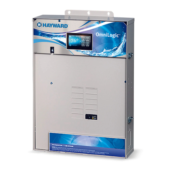
Overview The OmniLogic HLBASE is a multifunction pool automation control that is expandable to meet all your needs and fully manage your pool/spa system. The Om- niLogic can control pumps, valves, lighting, heaters, pool chemistry and more. It offers the next generation of technology to manage pool/spa equipment and the backyard experience. - Page 6 Features The standard Hayward HLBASE OmniLogic offers the following features: • control up to 4 high voltage (120/240V) relays to control pumps, pool lights, yard lights, water features, chemical dispensers and more • control up to 4 automatic valve actuators including pool and spa valves, water feature valves, cleaner valves and more • control up to 4 heaters or low voltage equipment including gas heaters, electric heat pumps, and solar heaters as well as various low voltage devices • inputs for up to 4 temperature sensors or external input devices • ethernet port for wired connection to the home’s router/access point allowing communication to devices on the home network or on the web • 100A electrical subpanel that can accommodate up to 12 circuit breakers • connection for Hayward TurboCell used to generate chlorine • connection for flow switch used to detect water flow • input for ORP and pH sensing (HL-CHEM) • connection for Expansion Panel if more than on OmniLogic is required Optional accessories (page 1) can expand the functionality of the HLBASE. Determine your needs and select the necessary HLBASE accessories before you begin the installation.
-
Page 7: Installation Steps
Chlorination When used with an optional Hayward TurboCell and P-KIT, the OmniLogic can generate all the chlorine needs for pools up to 40,000 gallons (150,000 liters), or the needs of most commercial pools up to 25,000 gallons (95,000 liters). If enabled (see Configuration Wizard), this operation requires a low concentration of salt (sodium chloride) in the pool/spa water. -
Page 8: General Water Chemistry
General Water Chemistry Salt is required only if you are using the chlorinator features on the OmniLogic Control Center. If you are NOT using the chlorinator, it is recommended that you follow all of the other chemistry recommendations besides salt. -
Page 9: Salt
A low salt level will reduce the efficiency of the sanitization and result in low chlorine production. A high salt level can cause the OmniLogic to stop chlorinating. The salt in your pool/spa is constantly recycled and the loss of salt throughout the swimming season should be minimal. -
Page 10: Mounting Equipment
Note that there is a heatsink on the back of the enclosure. Refer to the following information regarding the OmniLogic heatsink: In all cases the heat sink on the back of the OmniLogic panel should not contact the wall behind the panel. This restricts air flow and makes the heat sink less efficient. -
Page 11: Temperature Sensors
For Vinyl Siding - 3/8” Temperature Sensors Three sensors are included with the OmniLogic. A water sensor and an air sensor must be installed at all times for proper operation. A solar sensor is required if the solar function is enabled. -
Page 12: Optional Chlorination
The OmniLogic offers ethernet connectivity to the web through the home’s network. Once connected, web enabled devices such as a PC, laptop, tablet or phone can be used to control and monitor the OmniLogic. For web connectivity, an ethernet cable must be run from the OmniLogic to the router or access point or a wireless connection can be made to the home’s router using an optional HLWLAN. -
Page 13: Plumbing
POP-UP Some important notes regarding standard Pool/Spa systems: The OmniLogic can be programmed to accommodate spa spillover, if desired. A conventional heater (gas or heat pump) and solar can be used to heat both the pool and the spa. If the chlorinator cell is plumbed prior to the pool/spa return valve, then both the pool and the spa can be chlorinated The water sensor should be installed prior to any heater or solar and will display either the pool or the spa temperature, depending on the current operation of the pool. - Page 14 The chlorinator cell must be installed in the pool plumbing. If spillover is enabled, then the OmniLogic can chlorinate both the pool and spa (during spillover operation). Otherwise, the OmniLogic will only chlorinate the pool and the spa sanitization will have to be handled manually.
- Page 15 The chlorinator cell and flow switch must be installed in the heater return path. If spillover is enabled, then the OmniLogic can chlorinate both the pool and spa (during spillover operation). Otherwise, the OmniLogic will only chlorinate the pool when the spa does not control the heater(s) and the spa sanitization will have to be handled manually.
-
Page 16: Turbocell
Flow Switch (supplied with P-KIT) A Hayward flow switch is required if using the optional TurboCell for chlorination or an AQL-CHEM2 for pH dispensing. The flow switch is a safety device that ensures that water is flowing through the cell before the OmniLogic starts to generate chlorine or dispenses acid. -
Page 17: Wiring
Electrical Wiring The OmniLogic requires both high and low voltage connections. Low voltage connections will be made to actuators, sensors, remote keypad, etc. High voltage connections will be made to pumps, lights, etc., as well as providing direct input power to the Control Center. Always:... -
Page 18: Main Service
Grounding and Bonding Connect a ground wire from the primary electrical panel to the OmniLogic ground bus bar. Also ground each piece of high voltage (120 or 240VAC) equipment that is connected to the OmniLogic control relays or circuit breakers. The OmniLogic should also be connected to the pool bonding system by an 8AWG (6AWG for Canada) wire. -
Page 19: Pool Equipment Connection Table
You’ll need to record which input/output is used and what equipment is attached. To aid in this process, use the table below. To identify the vari- ous inputs/outputs, refer to the diagram on the side of the table. After attaching a equipment to the OmniLogic, fill in the appropriate information in the table. -
Page 20: High Voltage Pool Equipment
High Voltage Relays - (120/240V) Pool Equipment All OmniLogic relays are double pole (they make/break both “legs” of 240V circuits) and are rated at 3HP/30A at 240V (1½HP/30A at 120V). Refer to the diagram below for typical relay wiring. Record all connections using the table on page 15. -
Page 21: Low Voltage Wiring
Dispense Output When used with a Hayward HL-CHEM, a pH dispensing device may be used. The HL-CHEM is an ORP and pH sensing kit that is offered as an accessory for OmniLogic pool automation controls. The HL-CHEM continuously tests the pool’s sanitization and pH levels allowing the OmniLogic to automatically generate the correct amount of chlorine and dispense the proper amount of pH reducer. - Page 22 Heater Control The HLBASE OmniLogic provides a set of 4 low voltage dry contacts that can be connected to most gas heaters or heat pumps with 24V control circuits. When used with the optional Input/Output Expander Board (HLIOEXPAND), 8 dry contact relays are available. Refer to the diagram below for a generic heater con- nection.
- Page 23 3. Wire the OmniLogic to the “Ext Switch” connector as shown below. 4. The wires to the OmniLogic must be separated from any line voltage wires. Failure to follow these instructions may cause erratic operation of the heater. 5. Set the Power (Thermostat Select) switch to either “Pool” or “Spa”.
- Page 24 IMPORTANT: The heater will display “OFF” when it is being remotely controlled by the OmniLogic. Some homeowners see the “OFF” display and, thinking this is a mistake, change the mode to “POOL” or “SPA” which then disables the remote control by the OmniLogic. To prevent this: Remove the heater touch pad connector (P5) which will disable the touchpad.
- Page 25 The OmniLogic utilizes 10K ohm thermistor type sensors and provides three inputs. Three sensors (water temperature, air temperature and solar or dual equip- ment spa temperature) are included. If the OmniLogic is being used to control a solar heating system, the solar sensor is required. If dual equipment will be used, the dual equipment spa sensor is required.
- Page 26 HL-CHEM ORP and pH Sensing Kit Plug in the connector from the HL-CHEM into one of the Low Speed Bus connectors on the main PCB in the OmniLogic Control Center as shown below. Refer to the HLCHEM manual for complete installation instructions.
-
Page 27: System Startup
When all input and pool related wiring is complete, replace and secure the deadfront. The OmniLogic can now be powered on for the first time. Apply power at the main panel and wait for the OmniLogic to completely start. This may take a full minute or two. Because this is the first time that the OmniLogic has been powered on, it will bring you directly to the initial configuration screen shown below. -
Page 28: Startup And Configuration Wizard
Time and Date - Set the current date and time using a 12hr clock (AM/PM) or 24hr clock (military time). Save by touching the Save button when finished. Zip Code - This is used to display the current weather if the OmniLogic is connected to the internet. Select the box, then input your zip code. Touch the Advance button when finished. -
Page 29: Bodies Of Water
How many Bodies of Water? The OmniLogic can support one or two bodies of water, typically a pool and spa. Select the number and advance. You’ll be brought to a screen where you can add, delete or edit a body of water (BOW). When initially configuring the OmniLogic, a “?” will appear in the BOW icon. You will have to configure this body of water by selecting it and then touching the Advance button. - Page 30 Flow Monitoring Enabled? Requires use of a Hayward flow switch. This feature will help protect the filter pump from damage due to no flow. When Yes is selected, the OmniLogic will monitor the state of water flow when the filter pump is on. If no flow is detected for more than 20 minutes, the OmniLogic will shut down the pool pump and will indicate an error.
-
Page 31: Heaters
Does the Solar Heater Have a Valve? Select whether the solar heating system has a diverter valve to route pool/spa water through the solar collectors. If so, the OmniLogic will rotate this valve when the pool temperature is below the heater setting and there is solar heat available. -
Page 32: Hl-Chem
Sense and Dispense devices. Select the HLCHEM from the table and touch the Save button to save. The address should now be shown. Touch the Advance button to continue configuring the OmniLogic for use with the HLCHEM. -
Page 33: Chlorinator
Name of Cleaner - Touch the box and use the keyboard to name the cleaner. Does Cleaner Have a Pump? Select whether the cleaner has a dedicated pump. If so, the OmniLogic will turn this pump on when the cleaner is scheduled to run. -
Page 34: Water Features
Do you have ColorLogic Lights? Select yes if you are using any type of Hayward ColorLogic pool or spa lights. Note that the OmniLogic can only support USE ONLY HAYWARD GENUINE REPLACEMENT PARTS... -
Page 35: Colorlogic Lights
Name of Accessory - Touch the box and use the keyboard to name the accessory. Does Accessory Have a Pump? Select whether the accessory has a dedicated pump. If so, the OmniLogic will turn this pump on when the accessory is scheduled to run. -
Page 36: Sensors
FLOW SWITCH 1) and touch the Save button to save. The sensor connection should now be shown in the box and you can advance to the next screen to continue configuration. Do You Have an External Interlock Sensor? Select whether there is an external interlock sensor wired to the OmniLogic. To learn more about interlocks, refer to the interlock section on the following page. -
Page 37: Backyard Accessories
Would You Like to Add an Interlock? An interlock will allow the OmniLogic to turn on or to turn off a piece of pool equipment (slave) based on the state of other pool equipment (master). An example of this is would be the desire to turn on walkway lighting (slave) every time the pool deck lights (master) are turned on. - Page 38 Interlock is Active When Sensor is: - Select either High or Low. For normally open switches, select High. For normally closed switches, select Low. The OmniLogic will summarize the interlock logic. If the statement is true, select Yes. If not, select No and edit the interlock. If Filter is selected: Select Body of Water’s Filter you Wish to Interlock to - Touch the box and select the BOW that the filter pump (master) is...
-
Page 39: Omnilogic Limited Warranty
(3) years. Hayward also warrants its Aqua Trol chlorination products to be free of defects in materials and workmanship, under normal use and service for a period of one (1) year. These war- ranties are applicable from the initial date of purchase on private residential swimming pools in the US and Canada. - Page 40 USE ONLY HAYWARD GENUINE REPLACEMENT PARTS...
- Page 41 USE ONLY HAYWARD GENUINE REPLACEMENT PARTS...
- Page 42 USE ONLY HAYWARD GENUINE REPLACEMENT PARTS...
- Page 43 USE ONLY HAYWARD GENUINE REPLACEMENT PARTS...
- Page 44 Dispense are trademarks of Hayward Industries, Inc. © 2013 Hayward Industries, Inc. All other trademarks not owned by Hayward are the property of their respective owners. Hayward is not in any way affiliated with or endorsed by those third parties.
Need help?
Do you have a question about the OmniLogic and is the answer not in the manual?
Questions and answers
How bad 4A fuse transformer & cell circuit affects the valves actuator not working.
Can the hayward flow switch be plumbed in vertically or does it have to be horizontal?