
Related Manuals for GE PAC8000 series


Summary of Contents for GE PAC8000 series
- Page 1 Intelligent Platforms Programmable Control Products PAC8000* IO PROFINET Scanner User’s Manual, GFK-2839B September 2017...
- Page 2 Features may be described herein which are not present in all hardware and software systems. GE Intelligent Platforms assumes no obligation of notice to holders of this document with respect to changes subsequently made.
- Page 3 Contact Information If you purchased this product through an Authorized Channel Partner, please contact the seller directly. General Contact Information Online technical support and GlobalCare http://www.ge-ip.com/support Additional information http://www.ge-ip.com/ Solution Provider solutionprovider.ip@ge.com Technical Support If you have technical problems that cannot be resolved with the information in this guide, please contact us by telephone or email, or on the web at www.ge-ip.com/support...
-
Page 5: Table Of Contents
Contents Chapter 1. Introduction ..................7 PAC8000 PROFINET Scanner Overview ..............7 PAC8000 PROFINET Scanner Versions ..............8 PAC8000 PROFINET Scanner Specifications ............9 PAC8000 PROFINET Scanner Controls and Indicators ......... 10 1.4.1 PAC8000 PROFINET Scanner LEDs ............10 1.4.2 Power Supplies ....................11 1.4.3 External BFP (Bussed Field Power Supply) Monitoring ........ - Page 6 Contents Clearing the IO-Controller Configuration ..............37 Replacing PAC8000 PROFINET Scanner Hardware..........37 Chapter 4. Diagnostics ..................38 PNS Status and Control Data .................. 38 4.1.1 Output Control Register ................. 38 4.1.2 Input Status Registers ..................39 Error Handling ......................41 4.2.1 Fatal Error Handling ..................
-
Page 7: Chapter 1. Introduction
Index Chapter 1. Introduction This chapter provides an overview of the PAC8000 PROFINET Scanner (PNS) module and its operation. This chapter also includes a list of the PAC8000 IO modules that can be included in the PAC8000 PROFINET Scanner IO-Device. Chapter 2, Installation, gives instructions for PNS installation, panel-mounting, grounding, installing power supplies, and updating firmware. -
Page 8: Pac8000 Profinet Scanner Versions
Contents PAC8000 PROFINET Scanner Versions The PNS network interface module is available in two versions to allow you to use the network media that meet the requirements of your application. 8515-BI-PN: Two 10/100 Mbps copper RJ-45 media connectors supporting shielded (refer Note below) and unshielded cables (CAT 5 and above) 8516-BI-PN: Two 100Mbps Multimode SC–Duplex fiber optic media connectors The above PNS modules require the following carrier. -
Page 9: Pac8000 Profinet Scanner Specifications
Index PAC8000 PROFINET Scanner Specifications PROFINET Support PROFINET Version 2.3 Class A IO-Device Redundantly controlled operation conforms to PROFINET V2.3 Type S2 System Redundancy. RX3i PLC CPU Version Firmware version 7.0 or later Required Proficy Machine Edition Version 7.5 SIM 3 or later Version Required V2.3 GSDML and Proficy Machine Edition/3rd-Party tools. -
Page 10: Pac8000 Profinet Scanner Controls And Indicators
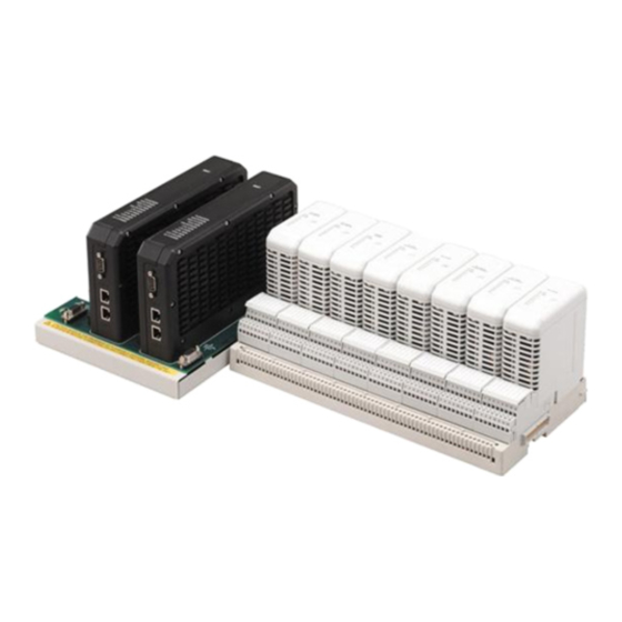
Contents PAC8000 PROFINET Scanner Controls and Indicators The illustration below shows a PAC8000 PROFINET Scanner. 1.4.1 PAC8000 PROFINET Scanner LEDs POWER LED Power Supply LED is ON solid green when power is being supplied on the power supply connector. OK LED The OK LED is solid green ON for normal operation. -
Page 11: Power Supplies
Index FAULT LED The FAULT LED remains OFF during normal operation when no PROFINET Diagnosis conditions are present on the PNS itself or any IO module in the node. When a PROFINET Diagnosis condition exists, the FAULT LED turns solid red. When all diagnosis conditions have disappeared, the FAULT LED is OFF. -
Page 12: External Bfp (Bussed Field Power Supply) Monitoring
Contents 1.4.3 External BFP (Bussed Field Power Supply) Monitoring The status of up to four Bussed Field Power supplies can be monitored through the status bits of the PNS. For details, see 4.1.2.3, “PNS Power Status Register (PPSR).” The Bussed Field Power monitoring connector is shown in the picture below. -
Page 13: Ethernet Network Ports
Index 1.4.5 Ethernet Network Ports The two external Ethernet ports are on the bottom of the module. The illustration below is a side view of 8515-BI-PN with its two RJ-45 ports. 8515-BI-PN (Copper) RJ-45 Port SC-Duplex Port PAC8000* IO PROFINET Scanner User’s Manual–September 2017 GFK-2839B... - Page 14 Contents 8516-BI-PN (Fiber) Model 8515-BI-PN has two RJ-45 ports, providing 10/100 Mbps copper interfaces. Model 8516-BI-PN has two SC-Duplex ports, providing 100Mbps Multimode fiber interfaces. Each Ethernet port automatically senses the type of network and adjusts speed and connection parameters. The PNS requires at least one port be operating at full duplex for a connection to remain established.
- Page 15 Index The PNS supports the following network media type and distances. Media Type Connector Wavelength Media Core Modal Bandwidth Distance (m) Size(μm) (MHz – Km) Type (nm) Type 2 – 2,000 100BASE-FX SC or 1300 62.5 SC-Duplex (Full Duplex) 2 – 400 (Half Duplex) 10/100BASE-T RJ45...
-
Page 16: Usb Port
Contents 1.4.5.1 Media Redundancy Protocol Support PROFINET Media Redundancy Protocol (MRP) supports devices configured in a ring topology. It is based on the functions of IEC62439. Media Redundancy Protocol is not routable between different IP subnets. Each device within a Redundant Media network has at least two physical pathways to two other devices on the network. -
Page 17: Compatible Pac8000 Io Modules, Carriers, And Power Supplies
Index Compatible PAC8000 IO Modules, Carriers, and Power Supplies 1.5.1 IO Modules The following modules can be used in a PAC8000 PROFINET Scanner IO-Device: Module Catalog No. Description Type 8101-HI-TX 8-channel Analog Input Module, 4–20 mA 8102-HO-IP 8-channel Analog Output Module, 4–20 mA 8103-AI-TX 8-channel Analog Input Module, 4–20 mA 8104-AO-IP... -
Page 18: Power Supply Requirements
Contents 1.5.4 Power Supply Requirements 1. The power supply shall have output ratings of 12V DC, 5 A with power fail signal. 2. The power supply shall be current limited and shall meet the output entity parameter requirements as per our drawing no. SCI-1520 / SCI-1526. 3. -
Page 19: Chapter 2. Hardware Installation
Index Chapter 2. Hardware Installation This chapter describes: ■ Module Installation Installing the Module on a DIN Rail Removing the Module from the DIN Rail Panel-Mounting Grounding Installing Power Supplies ■ PNS Powerup and Restart ■ LED Operation Special LED Blink Patterns ■... - Page 20 Contents PAC8000* IO PROFINET Scanner User’s Manual–September 2017 GFK-2839B...
-
Page 21: Cable And Connector Clearance Requirements
Index Cable and Connector Clearance Requirements You may need to allow more space for installation of cables and connectors than what is required for heat dissipation. To avoid impacting mechanical reliability and signal quality, cable installation must comply with the minimum bend radius specified by the cable manufacturer. -
Page 22: Installation In Hazardous Areas
Contents Installation in Hazardous Areas The following information is for products bearing the UL marking for Hazardous Locations or ATEX marking for explosive atmospheres: • EQUIPMENT LABELED WITH REFERENCE TO CLASS I, DIVISION 2, GROUPS A, B, C & D, HAZARDOUS LOCATIONS (ALTERNATIVELY MARKED AS CLASS I ZONE 2, GROUP IIC) IS SUITABLE FOR USE IN CLASS I, DIVISION 2, GROUPS A, B, C, D OR NON-HAZARDOUS LOCATIONS ONLY ▪... -
Page 23: Installing The Module On A Din Rail
Index Installing the Module on a DIN Rail The PNS and connecting carriers must be installed on the same section of 35mm x 7.5mm DIN rail. The rail must have a conductive (unpainted) finish for proper grounding. For best resistance to vibration, the DIN rail should be installed on a panel using screws spaced approximately 6 inches (5.24cm) apart. -
Page 24: Removing The Module From The Din Rail
Contents Step 3: Guide the module into the connectors and lock them with two plastic screws with 4.5 N-m Removing the Module from the DIN Rail 1. Remove the screws of PNS and pull the module from the carrier. 2. Unlock four screws with a small flathead screw driver, shown in step 2 of installation instruction. -
Page 25: Grounding
Index Grounding The PAC8000 PROFINET Scanner has one system ground for which the ground terminal is available on the carrier as shown below. The carrier also has provision for a BFP (expand) ground. Connecting Power Supplies to PAC8000 PROFINET Scanner The PAC8000 PROFINET Scanner has connectors for either one or two power supplies. -
Page 26: Pac8000 Profinet Scanner Power-Up And Restart
Contents PAC8000 PROFINET Scanner Power-up and Restart Once PNS is powered up, the OK LED remains ON. If a fatal error occurs during powerup, the LED blinks instead. If the module encounters a hardware failure, invalid firmware image, or the powerup diagnostics fail, the module will not become operational;... -
Page 27: Led Operation
Index LED Operation 2.10 The following table summarizes the operation of the PAC8000 PROFINET Scanner’s LEDs: Name Color Description POWER Green ON = Power OK OFF = No power Green ON = PNS is OK and has completed system boot up successfully FAST BLINK pattern: See 2.10.1, “Special LED Blink Patterns”... -
Page 28: 2.10.1 Special Led Blink Patterns
Contents 2.10.1 Special LED Blink Patterns Multiple LEDs can blink in patterns that indicate special conditions: LEDs Involved Pattern Displayed Description CONNECT, FAULT, CONNECT, FAULT, LAN, PORT 1, PORT Module identification requested LAN, PORT 1, 2 LED's go ON in order, from bottom to (Initiated by PME or any DCP PORT 2 top. -
Page 29: Firmware Updates
Index Firmware Updates 2.11 The PAC8000 PROFINET Scanner enters firmware update mode when commanded to do so from the Winloader update utility, or if a firmware component is corrupted or invalid. In firmware update mode, the PNS module blinks its LEDs in a special pattern as described previously, and its Ethernet ports are not operational. -
Page 30: Installing The Usb Port Driver
Contents Installing the USB Port Driver 2.12 The USB port is only used for firmware updates. USB driver files are provided as part of upgrade packages compatible with the PNS. With the provided installation files accessible on either a local or network drive, connect the computer’s USB port to the PAC8000 PROFINET Scanner’s USB port. -
Page 31: Chapter 3. Configuration
Index Chapter 3. Configuration This chapter provides general information for configuring a PAC8000 PNS and its IO modules in a PROFINET-IO network. For information on configuring the PROFINET IO-Controller and its network, refer to the IO-Controller manufacturer’s documentation. Note: To configure RX3i Controller, refer to the PACSystems RX3i PROFINET Controller Manual, GFK-2571. -
Page 32: Basic Configuration Steps
Contents 3.1.1 Basic Configuration Steps The basic configuration steps are: ■ Configure a PROFINET IO-Controller and its PROFINET LAN using the Controller manufacturer’s recommended PROFINET IO configuration tool. ■ Configure the parameters of the PROFINET IO-Controller. ■ Add IO-Devices to the LAN. These IO-Devices can be PAC8000 PROFINET Scanner modules or third-party IO-Devices. -
Page 33: Adding A Pac8000 Profinet Scanner To A Lan
Index Adding a PAC8000 PROFINET Scanner to a LAN Use the PROFINET IO configuration tool to add a PNS module to the LAN. This process may include importing the PNS module’s GSDML files. If necessary for your application, change the settings of the PNS module’s configurable parameters listed below. 3.2.1 Configuring PAC8000 PROFINET Scanner Parameters The PROFINET IO Scanner provides 64-bits of status data and receives 16-bits of output... - Page 34 Contents Profinet Profinet HOST Controller HOST Controller PROFINET IO Profinet Profinet Device Device The “Redundancy mode” tab in the configuration tool selects whether or not the PNS to be redundantly controlled. When it is configured for “HSB CPU Redundancy”, the PROFINET System Redundancy feature in PNS gets enabled.
- Page 35 Index Communication Timeout Control application (PROFINET Controller) should toggle Heartbeat bit (refer Output Control Register) to indicate it is alive. When there is no update to this bit for more than configured communication timeout time, the PNS treats it as a communication/application failure and goes to failsafe state.
-
Page 36: Configuring Pac8000 Profinet Scanner Parameters
Contents 3.2.2 Configuring PAC8000 PROFINET Scanner Parameters After adding PAC8000 PROFINET scanner(s) to the PROFINET IO Controller in the programmer, their parameters must be configured. Configuration details for basic parameters are given in the following pages. 3.2.2.1 Basic Module Parameters The PNS parameters define how the IO-Controller scans and stores the PNS data. -
Page 37: Assigning Io-Device Names
Index Assigning IO-Device Names After the PNS and other IO-Devices on the LAN have been entered into the configuration, a Discovery and Configuration Protocol (DCP) tool must be used to assign a name to each IO- Device. The Name of each device on the LAN must match the configuration. This step is required before downloading the configuration from the PROFINET IO-Controller, otherwise the PROFINET IO-Controller will be unable to connect to the devices and deliver their configuration. -
Page 38: Chapter 4. Diagnostics
Contents Chapter 4. Diagnostics This chapter describes: ■ PNS Status and Control Data Output Control Register Input Status Registers PNS Status register PNS Network port status register PNS Power status register PNS Module health status register ■ Error Handling Fatal Error Handling PROFINET Alarms PROFINET Module Loss, Add &... -
Page 39: Input Status Registers
Index 4.1.2 Input Status Registers Byte Register Description PNS Status Register (PSR) Device/Scanner Status PNS Network Port Status Register (PNSR) Network Status PNS Power Status Register (PPSR) Power Status Module Health Status Register (MHSR) IO module Health Status 4.1.2.1 PNS Status Register (PSR) The PSR provides 16 bits of information about the PNS module. - Page 40 Contents 4.1.2.3 PNS Power Status Register (PPSR) The PPSR provides 8 bits of information about the power supply. All status bits are active high. Status Name Description Bits 1 (LSB) Power Line 1 Status 1 = Power supply is healthy 0 = Power supply failed Power Line 2 Status 1 = Power supply healthy...
-
Page 41: Error Handling
Only information about the most recent fatal error is retained. This information is available on future power cycles to be retrieved and sent to GE Intelligent Platforms for analysis. While diagnostic information is being saved, the PNS blinks its OK LED. The PNS disables Ethernet and USB communications, so communication with the module is not possible. -
Page 42: Profinet Diagnostics
Contents 4.2.2 PROFINET Diagnostics The PNS reports its own non-fatal errors and errors on modules using PROFINET Diagnosis or PROFINET Pull/Plug alarms. 4.2.2.1 PROFINET Diagnosis Alarms Diagnosis Alarms indicate any fault conditions other than a module add, loss, or mismatch that a PAC8000 PROFINET Scanner needs to communicate to the PROFINET IO-Controller. - Page 43 Check the Bused Field Power Channel Diagnosis Channel Channel detected fault ADC Error Detected of the IO carrier . If it is ok, Appears/Disappears in ADC contact GE-IP support team for help. Channel Diagnosis Channel Channel configuration Parameterization In configuration tool adjust the Appears/Disappears...
- Page 44 Contents Channel Diagnosis Alarm Module Cause Fault Text Recommendation Error Type Type Channe l Error Channel configuration Channel Diagnosis Channel Parameterization In the configuration tool, set has invalid pulse Appears/Disappears error in failsafe the parameters properly and settings. This fault occurs after value/Pulse download the configuration...
-
Page 45: Clearing Faults On Pac8000 Modules
Channel fault Verify Channel fault Appears/Disappears Secondary data fault Channel Diagnosis Channel Secondary data fault Verify Secondary data fault Appears/Disappears 4096 Contact GE-IP support team Channel Diagnosis Module Module is in fault state Module Fault Appears/Disappears Detected 4097 Channel Diagnosis Module... -
Page 46: Profinet Module Loss, Add And Mismatch Faults
Contents 4.2.4 PROFINET Module Loss, Add and Mismatch Faults The PAC8000 PROFINET Scanner uses standard PROFINET Pull/Plug alarms to indicate differences between the configured modules and the actual modules present in the PNS. ■ If a module is configured, but is not present or not operating correctly, the PNS indicates the module as removed via a Pull Alarm. -
Page 47: Chapter 5. Profinet Specifications
Index Chapter 5. PROFINET Specifications Release 2.00 of the PAC8000 PROFINET Scanner supports PROFINET v2.3 Class A IO-Device with the clarifications listed below. For version-specific updates, refer to the Important Product Information document provided with your module. PROFINET Protocol Support RTC –... -
Page 48: Limitations
Contents Limitations The following features are not supported. RT over UDP Multicast communication DHCP DCP Hello service DNS (Domain Name Service protocol) FastStartUp Supervisor-AR. Note: Supervisor-DA-AR is supported. (Device Access supported) Optical power diagnostics (IC200PNS002) Substitute Data Only one Input-CR and one Output-CR are supported. 8515-BI-PN, 8 clearing, 44 8516-BI-PN, 8... -
Page 49: Pac8000* Io Profinet Scanner User's Manual–September
Index adding to a LAN, 33 PROFINET support, 9, 46 LEDs, 10 Replacing PROFINET Scanner hardware, overview, 7 RoHS Compliance, 9 parameters, 33 Status and Control Bits, 9 specifications, 9 Status and Control Data Port Connectors, 9 PAC8000 PROFINET Scanner, 38 Power Requirements, 9 Technical Support, 3 Power supply modules, 11... - Page 50 1-800-433-2682 or 1-434-978-5100 www.ge-ip.com Global regional phone numbers are available on our web site www.ge-ip.com ©2013 GE Intelligent Platforms, Inc. All Rights Reserved *Trademark of GE Intelligent Platforms, Inc. All other brands or names are property of their respective holders. GFK-2839B...