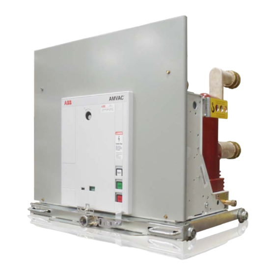
ABB AMVAC Installation And Operation Manual
Medium voltage vacuum circuit breakers
Hide thumbs
Also See for AMVAC:
- Manual (23 pages) ,
- Technical manual (16 pages) ,
- Technical manual (12 pages)
Table of Contents
Advertisement
Advertisement
Table of Contents

Related Manuals for ABB AMVAC


Summary of Contents for ABB AMVAC
- Page 1 AMVAC™ Medium Voltage Vacuum Circuit Breakers Installation and Operation Manual...
- Page 2 1VAL050601-MB Rev C...
-
Page 3: Table Of Contents
ABLE OF ONTENTS FOREWORD ................................4 INTRODUCTION & SAFE PRACTICES ........................5 RECEIVING, HANDLING, AND STORAGE ......................6 ACCESSORIES ................................. 7 Lifting Hook ..............................7 Racking Handle ............................8 Manual Opening Handle..........................8 INSERTION AND REMOVAL ........................... 9 Racking ............................... -
Page 4: Foreword
This booklet provides information for the Medium Voltage (5kV to 27kV) AMVAC indoor circuit breakers as described below. Note: not all sections of this bulletin appllies to all the types of AMVAC circuit breakers. For example, the racking and interlock sections only apply to the draw-out (removable) versions and do not apply to the fixed-mount breaker styles. -
Page 5: Introduction & Safe Practices
NTRODUCTION The purpose of this manual is to provide instructions for unpacking, storage, installation, operation, and maintenance for AMVAC™ vacuum circuit breakers. This manual should be carefully read and used as a guide during installation, initial operation, and maintenance. The specific ratings of each model circuit breaker are listed on the individual nameplates. The AMVAC™ circuit breakers are protective devices. -
Page 6: Receiving, Handling, And Storage
ABB representative. ABB is not responsible for damage of goods after delivery to the carrier. However, ABB will lend assistance if notified of claims. Use care in unpacking to avoid damaging any circuit breaker parts. -
Page 7: Accessories
ACCESSORIES IFTING The lifting hook is specifically designed for general lifting and lowering of the vacuum circuit breaker, from shipping pallets or for lifting onto and off of work tables. The lifting hook is not designed to be used for insertion or removal of the circuit breaker from the switchgear compartment, instead, the use of an appropriate lift truck is required or serious damage to the breaker may occur. -
Page 8: Racking Handle
Racking Handle CAUTION Use of any other racking device not approved by ABB will void the warranty!! ABB will not be responsible for damage caused by the use of racking tools other than ABB’s. ANUAL ANDLE The manual opening handle (1) is designed to open the AMVAC circuit breaker manually. -
Page 9: Insertion And Removal
The following rules should always be observed when inserting a circuit breaker into the switchgear compartment. NOTE: ABB has specific accessories to be used with ABB breakers. ALWAYS compare the breaker ratings nameplate with the switchgear ratings nameplate. Verify breaker secondary control voltage ratings are in agreement with the switchgear control voltage ratings. - Page 10 8. Depending on breaker options, the stored energy capacitor may or may not retain a charge. For AMVAC breakers, a warning label will be located on the breaker front cover indicating a 10 minute wait time before front cover removal to allow for the capacitors to discharge.
-
Page 11: Racking
INSERTION AND REMOVAL ACKING AMVAC™ circuit breakers are provided with three positive stop racking positions. “Disconnect” position allows for (door open) manual opening only through the use of the manual opening handle (spring loaded) or operation through the use of the electrical close / open pushbuttons located on the breaker front escutch- eon, provided this operation is performed within 200 seconds from the time control power was last applied. - Page 12 INSERTION AND REMOVAL 2. Begin racking procedure using approved racking crank: a. Insert racking crank socket into breaker door access port and rotate until socket slides into position. b. Hold racking crank with left hand and depress position lever with right hand. c.
-
Page 13: Structure And Function
STRUCTURE AND FUNCTION IRCUIT REAKER TRUCTURE (Refer to Figure 2) TRUCTURE OF THE CIRCUIT BREAKER POLES The encapsulated poles are mounted on the rear flat section of the circuit breaker enclosure. The live parts of the circuit breaker poles are enclosed in cast resin and protected from impacts and other external influences. With the circuit breaker closed the current path for each pole leads from the upper circuit breaker terminal (25) to the fixed contact (24.2) in the vacuum interrupter (24), then via the moving contact (24.1) and the flexible connector (21) to the lower circuit breaker terminal (22). - Page 14 STRUCTURE AND FUNCTION TORAGE CAPACITORS (Figure 2c) The energy for the operation of the circuit breaker is stored electrically in two storage capacitors. The breaker is de- signed in such a way that when the capacitors are fully charged, there is enough energy for an O-C-O (Open-Close- Open)* operating sequence without the recharging of the capacitors.
- Page 15 STRUCTURE AND FUNCTION IRCUIT REAKER ONTROL All the conditions for control of the magnetic actuator mechanism are defined in a permanently programmed logic module. These conditions are: Auxiliary voltage must be applied to the AC/DC converter. The storage capacitors must have sufficient charge for the next switching operation. ...
- Page 16 5 to 10 amps) for customer use. This package directly replaces an ADVAC circuit breaker having two secondary dis- connects. Package 3 is an AMVAC circuit breaker with all control board options available. See Appendix D for more detail regarding the wiring and termination points for each package.
- Page 17 STRUCTURE AND FUNCTION Figure 2b: Sectional view of a circuit breaker type, AMVAC schematic diagram Circuit breaker enclosure Front panel, removable Emergency manual opening mechanism Figure 2a: Circuit breaker front with controls Magnetic actuator Breaker enclosure OPEN coil 1.1 Front Plate Magnet armature 1.2 Lifting bracket, both sides...
-
Page 18: Operation, Installation And Maintenance
OPERATION, INSTALLATION, AND MAINTENANCE NTERLOCKS The AMVAC™ circuit breaker contains a number of interlocks. A description of each interlock follows as encountered during racking of the circuit breaker into the compartment. NTERFERENCE LOCKING A interference blocking plate (Fig. 1) in the circuit breaker compartment prevents under rated circuit breakers from being inserted into higher rated compartments. -
Page 19: Maintenance
Maintenance Schedule Establishing a periodic maintenance and inspection schedule are critical to ensure a safe, reliable operating AMVAC circuit breaker. Although the magnetically actuated operating mechanism of the AMVAC circuit breaker is maintenance free, visual inspection and maintenance on other components is required. -
Page 20: Truck
MAINTENANCE RUCK The truck requires visual inspection of hardware, lubrication and operations during routine maintenance. With the breaker outside the cell, verify all visible hardware tightness, including handles (9) and wheels (7). Wheels should rotate freely by hand movement. Replace or tighten any missing or loose hardware. With the breaker outside the cell, rotate the racking screw as though racking the breaker to the connect position. - Page 21 OPERATION, INSTALLATION, AND MAINTENANCE RIMARY IRCUIT SSEMBLY (Pole) The primary circuit requires visual inspection of hardware, low-frequency withstand voltage testing to insure vacuum, and lubrication during routine maintenance. All insulation material should be clean and free of structural cracks. Some minor cracks are inherent in the insulation material.
-
Page 22: Control Wiring
RIMARY IRCUIT SSEMBLY (Pole) To verify the integrity of the vacuum interrupters, perform the following low-frequency withstand voltage test: 1. Open the breaker (no control power supplied to breaker). a. Connect the high potential lead to one terminal. b. Ground the remaining 5 terminals and breaker frame. 2. -
Page 23: Appendices
APPENDICES APPENDIX A BASIC BREAKER LAYOUT All AMVAC circuit breakers have the same basic layout regardless of rating or pole configuration. Description FRONT PLATE ASSEMBLY CHARGED/DISCHARGED “READY” INDICATOR CLOSE PUSH BUTTON OPEN PUSH BUTTON OPERATION COUNTER CLOSE/OPEN INDICATOR RATING LABEL... -
Page 24: Appendix B: Basic Breaker Dimensions And Weights
APPENDICES APPENDIX B BASIC BREAKER DIMENSIONS AND WEIGHTS All AMVAC circuit breakers of this style have the same basic dimensions (i.e. pole spacing) regardless of pole configuration. RAWOUT REAKER 1VAL050601-MB Rev C... - Page 25 APPENDICES APPENDIX B BASIC BREAKER DIMENSIONS AND WEIGHTS All AMVAC circuit breakers of this style have the same basic dimensions (i.e. pole spacing) regardless of pole configuration. 1VAL050601-MB Rev C...
- Page 26 APPENDICES APPENDIX B BASIC BREAKER DIMENSIONS AND WEIGHTS All AMVAC circuit breakers of this style have the same basic dimensions (i.e. pole spacing) regardless of pole configuration. 1VAL050601-MB Rev C...
- Page 27 APPENDICES APPENDIX B BASIC BREAKER DIMENSIONS AND WEIGHTS All AMVAC circuit breakers of this style have the same basic dimensions (i.e. pole spacing) regardless of pole configuration. 1VAL050601-MB Rev C...
- Page 28 APPENDICES APPENDIX B BASIC BREAKER DIMENSIONS AND WEIGHTS All AMVAC circuit breakers of this style have the same basic dimensions (i.e. pole spacing) regardless of pole configuration. 1VAL050601-MB Rev C...
- Page 29 APPENDICES APPENDIX B BASIC BREAKER DIMENSIONS AND WEIGHTS All AMVAC circuit breakers of this style have the same basic dimensions (i.e. pole spacing) regardless of pole configuration. 1VAL050601-MB Rev C...
- Page 30 APPENDICES APPENDIX B BASIC BREAKER DIMENSIONS AND WEIGHTS All AMVAC circuit breakers of this style have the same basic dimensions (i.e. pole spacing) regardless of pole configuration. 1VAL050601-MB Rev C...
- Page 31 APPENDICES APPENDIX B TYPE MECHANISM CUBILE AMVAC 15kV 1200-2000A 50kA SAFEGEAR HD Weight 410lbs, 186Kg 1VAL050601-MB Rev C...
- Page 32 APPENDICES APPENDIX B TYPE MECHANISM CUBILE AMVAC 15kV 3000A 50kA SAFEGEAR HD Weight 420lbs, 190Kg 1VAL050601-MB Rev C...
-
Page 33: Appendix C: Ed2 Electronic Control Board
APPENDIX C APPENDIX C ED2 ELECTRONIC CONTROL BOARD Following are the basic characteristics for the control power and close and open operations of the AMVAC circuit breaker. CONTROL RANGE LOW VOLTAGE UNIT HIGH VOLTAGE UNIT Binary Inputs AC or DC... -
Page 34: 1.0 Overview
APPENDIX C LECTRONIC ONTROL OARD 1.0 OVERVIEW The actuator control board is comprised of a Power Supply Recharge Unit, Control Unit, and FET Switching circuit which connects the Storage Capacitors to the Magnetic Actuator coils. The power supply recharge circuitry adapts to whatever input voltage that is supplied within the specified in- put range on page 31 in order to maintain an 80 V charge across the storage capacitors. -
Page 35: Available Boards
Open and Close inputs, which draw up to approximately 20 milliamperes. The input impedance (Z) is 300kΩ except for binary inputs 1 and 2 (Remote Open and Close) which are around 14 kΩ input Z. There are seven different input channels. Only six of them are used for the AMVAC breaker (channel 5 is not used). - Page 36 APPENDIX C LECTRONIC ONTROL OARD Second Trip (KM1005, CH 4, Pins 7 and 8) This input can be configured as either a Protection Trip or Second Trip function. It is programmed via Jumper JP1001 Pins 1 and 2 or as a normal input by jumping JP1001 pins 2 and 3. The Protection Trip input is designed to work at a lower threshold of 7 VDC.
-
Page 37: Binary Outputs
APPENDIX C LECTRONIC ONTROL OARD BINARY OUTPUTS Binary outputs are pairs of mechanical wipe relay contacts. They can be employed to switch in other circuitry or to an alarm indicator. See Illustration 3 and 4 for the power limitations of the contacts. Notice the flat curve for AC voltage in Illustration 4. -
Page 38: Output Contact Specifications
APPENDIX C LECTRONIC ONTROL OARD CHARACTERISTIC WIPE CONTACTS RELAY SWITCHING CHARACTERISTICS Maximum Switching Power 1500 VA on Resistive load Maximum Switching Voltage 400 VAC, 300 VDC Maximum Switching Current Maximum Rated Current CONTACTS CHARACTERISTICS 100 mΩ (measured by voltage drop 6 Maximum On Resistance (Ron) VDC 1 A) Maximum Capacitance... -
Page 39: Features
Auxiliary Power supply input must be at least 93.75 W for the 75 W setting or 41.3 W for the 33 W setting. The 33 W option is hardware selectable with Jumper JP1019. RS-232 Port / JTAG Communication Port Used by ABB factory only. 1VAL050601-MB Rev C... -
Page 40: Power Considerations
APPENDIX C LECTRONIC ONTROL OARD POWER CONSIDERATIONS The control board power supply recharge unit adapts any voltage within the specified range of the board to maintain 80 V across the capacitors. The following voltage thresholds must be reached to complete the speci- fied operations: 1. -
Page 41: Ready Not Ready Status
APPENDIX C LECTRONIC ONTROL OARD Breaker Ready / Not Ready Binary Output Contacts and Ready Light Status CIRCUIT BREAKER POSITION CLOSE OPEN CONDITION Ready LED: on Ready LED: on Capacitor Energy sufficient For O-CO Ready contact: closed Ready contact: closed operations Not ready contact: opened Not ready contact: opened... -
Page 42: Ed2 Connections Jumpers And Dip Settings
APPENDIX C ED2.0 CIRCUIT BOARD CONNECTIONS, JUMPERS AND DIP SETTINGS I1001 KM1005 (INPUTS) 14 - Under voltage NOTE: The filter card has wire 13 + Under Voltage jumpers for each binary input. 12 - Close Blocking If the jumpers are left in- JP1001 11 + Close Blocking stalled,... -
Page 43: Appendix D: Wiring Diagrams
APPENDIX D * NOTE: On Fixed Mount Breakers ONLY P3-1 and P3-4 does not ex- ist. Pin 11 on KM1005 is directly wired to Pin 2 on KM1003 for the Lock Circuit Breaker open circuit. Also P1-16 wire 13 goes directly to Single secondary NOTE:... - Page 44 APPENDIX D 1VAL050601-MB Rev C...
-
Page 45: Appendix E: Wiring Diagrams
2. Wait 10 minutes for power to drain out of capacitor inside of breaker. 3. Remove 4 screws holding front cover then remove front cover of breaker and locate dip switches I1001, I1002 and I1004 using page 40 of AMVAC IB for reference. 4. Turn... -
Page 46: Appendix F: Auxiliary Contact Ratings
APPENDIX F 1VAL050601-MB Rev C... -
Page 47: Appendix G: Service Conditions
APPENDIX G 1VAL050601-MB Rev C... -
Page 48: Product Quality And Enviromental Protection
Product Quality and Environmental Protection ABB products are manufactured to meet or exceed the standards of compliance for quality and environmental manage- ment systems in accordance with ISO 9001 and ISO 14001. All of these items can be supplied with a certificate of quali-... - Page 49 NOTES 1VAL050601-MB Rev C...
- Page 50 +1 407 732 2000 in this document is subject to change without notice. Customer service +1 800 929 7947 ext. 5 © Copyright 2015 ABB Inc. All rights reserved. +1 407 732 2000 ext. 2510 E-Mail: customer.service.group@us.abb.com www.abb.com/mediumvoltage 1VAL050601-MB Rev C...