ABB VD4 Instruction Manual
Vacuum circuit-breaker on withdrawable part –
high duty
Hide thumbs
Also See for VD4:
- Installation and service instructions manual (73 pages) ,
- Product manual (56 pages) ,
- Instruction manual (44 pages)

Related Manuals for ABB VD4


Summary of Contents for ABB VD4
-
Page 1: Table Of Contents
Instruction manual BA 414/07 E Medium voltage products Vacuum circuit-breaker on withdrawable part – high duty Contents 1 Summary 2 Technical data 3 Circuit-breaker on withdrawable part 4 Operation of the switchgear 5 Maintenance... - Page 3 Your safety first – always! That’s why our instruction manual begins with these recommendations: • Only install switchgear and/or switchboards in enclosed rooms suitable for electrical equipment. • Ensure that installation, operation and maintenance are carried out by specialist electricians only. •...
- Page 4 5.5.3 Checking auxiliary switch settings on type A withdrawable parts 3.2.2 Basic equipment 5.5.4 Checking auxiliary switch settings 3.2.3 Mounting of the VD4 on trucks from on type B withdrawable parts other manufacturer 5.5.5 Checking the direction of rotation Operation of the switchgear...
-
Page 5: Summary
– the average value of the relative are expected. The vacuum circuit-breakers of the humidity, measured over a period type VD4, designed in column form, are suitable for of 24 h, does not exceed autoreclosing, and have exceptionally high operating –... -
Page 6: Technical Data
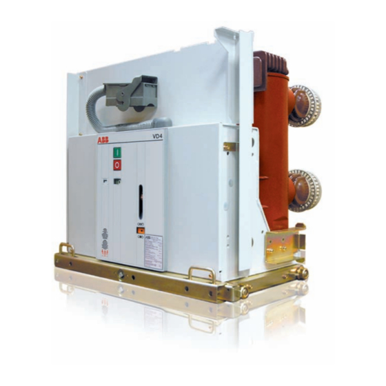
The weight raises about 5 kg for breakers with motor-operated mechanisms The weight raises about 2 kg for motor-driven withdrawable parts With fan cooling Together with this instruction manual, it is essen- tial to consult manual BA 359, Vacuum circuit- breaker type VD4, high current. - Page 7 Exists only for withdrawable parts of type A (see section 5.5) Exists only for rated currents above 2500 A with fan cooling Figure 2/1: Vacuum circuit-breaker on withdrawable part, type VD4 • Use in UniGear type ZS1 • 12 kV, ...2500 A, 50 kA, 12 kV, 3150/4000 A, ...50 kA...
-
Page 8: Circuit-Breaker On Withdrawable Part
Release of run-on block may only be performed by Withdrawable parts of the same version are inter- servicing personnel from ABB or adequately trained changable. With the same dimensions but different specialist stuff. -
Page 9: Basic Equipment
Auxiliary switch for fault annunciation Blocking magnet Auxiliary switches -S2, -S6 3.2.3 Mounting of the VD4 on trucks from other manufacturers VD4 circuit-breakers which are not installed on ABB Calor Emag withdrawable parts must be fitted with one or two additional auxiliary switches which are dependent on the mechanical lock and release device. - Page 10 10.2 13.9 13.6 13.13 Figure 3/1: Pole side of a withdrawable part with high-voltage Figure 3/2: Withdrawable part with circuit-breaker, type VD4, circuit-breaker, type VD4 mechanism side 13.9 Protective transport cover 10.2 Control wiring plug (remove before commissioning) 13.6 Socket for charging lever (9) 13.13 Lifting lug (remove before commissioning...
-
Page 11: Operation Of The Switchgear
Operation of the switchgear • On motor-driven withdrawable parts, check the direction of rotation of the travel motors as de- Note on safety at work scribed in section 5.5.5. • The switchgear may only be operated by spe- • For any further questions on the functions of the cially trained personnel who are familiar with the withdrawable circuit-breaker part and its testing, characteristics of the particular device. - Page 12 Note: Emergency manual operation is carried out with the hand crank (121) on the spindle mechanism (18), In order to avoid damage to the operating mecha- in a similar manner to operation of a withdrawable nism, use the original hand crank only. breaker part with manual systems: • Standard version without slip clutch • Turn off the supply voltage (m.c.b.), since the...
-
Page 13: Circuit-Breaker
4.2.2 Circuit-breaker Meaning of the charging condition symbols: (Figures 3/2 and 4/1) Charging the stored-energy spring system • On breakers with charging motors, charging is carried out automatically. If the charging motor Discharged Charged should fail, the charging procedure can be carried out or completed by hand. Opening and closing the circuit-breaker: • On breakers with manual charging systems, door • With the withdrawable part in the service position,... - Page 14 Figure 4/2: Movement of the withdrawable breaker part between the test/disconnected position and the service position, clockwise up to the stop for the service position and anti-clockwise for the test/disconnected position Withdrawable circuit-breaker part Spindle mechanism Hand crank 124.2 124.3 124.1 13.11 Figure 4/3: Approaching the panel and positioning the service truck...
-
Page 15: Maintenance
Maintenance work may only be performed by fully trained personnel, observing all the relevant safety The contact points should be cleaned if signs of regulations. It is recommended that ABB after-sales unperminable overheating (discoloured surface) service personnel should be called in, at least du- are visible (see section Repairs) ring the performance of servicing and repair work. -
Page 16: Withdrawable Assembly
– Check all contact fingers and annular tension porary remedy. It is advisable to request advice springs for perfect fit. from the ABB after-sales service department on permanent solutions to such unusual problems. Note: For details of servicing, see also the relevant sec- The set installation position of contact arms tions of manual BA 359. -
Page 17: Replacement Of Components
BA 359. • Move the withdrawable part out of the test/ disconnected position towards the service Testing withdrawable parts with a VD4 type position with a few turns of the crank. circuit-breaker • Slowly move the withdrawable part back to When functional tests are carried out on withdra- the stop. -
Page 18: Checking Auxiliary Switch Settings On Type B Withdrawable Parts
2. Settings in the area of the service position • Remove the hand crank. • Move the withdrawable part out of the limit po- • Switch the supply voltage for the travel motor on. sition towards the test/disconnected position • Use the local electrical controls to check that the with a few turns of the crank. withdrawable part moves in the correct direction. • Slowly move the withdrawable part forwards Caution: again to the stop: Do not allow the withdrawable part to run up against Auxiliary switch -S6 must then operate when a block when the travel direction is incorrect! Switch... -
Page 19: Spare Parts, Auxiliary Materials, Lubricants
No special notes required (table 1) 4. It must only be possible to open the circuit- breaker (manually) when the withdrawable part Withdrawable assembly of VD4 is in the service position or test/disconnected • Manually moveable withdrawable assembly : position and the control voltage has failed. - Page 20 Table 1: VD4 circuit-breaker Designation Item Rated supply Part-no. voltage (order code) • Auxiliary switches -S1 GCE7002397R0122 (with clamp type terminals) GCE7002397R0121 GCE7002397R0122 GCE7002397R01.. • Auxiliary switch on blocking magnet -S2 GCE7003022P0101 • Auxiliary switch for fault annunciation -S7 GCE0905121P0100 • 1st schunt release OFF -Y2 GCE7004590P01.. • 2nd shunt release OFF -Y9 GCE7004590R01.. • Shunt release ON -Y3 GCE7004590P01..
-
Page 21: Auxiliary Materials And Lubricants
Table 2: VD4 withdrawable assembly Designation Item Rated supply Part-no. voltage (order code) Auxiliary switch for manually operated mechanism (type A) GCE7004023R0101 Auxiliary switch for manually operated mechanism (type B) -S8/-S9 • contacts silver plated GCE7004024R0101 • contacts gold plated GCE7004024R0103 Auxiliary switches for motor-operated driving mechanism -S8/-S9 • contacts silver plated... - Page 22 13.2. 1 13.26 13.24 10.3 13.92 (-S6) 127.1 Figure 5/1: Fit the contact system back-to-front on the thin end of Figure 5/2: Motor-driven withdrawable part in an intermediate the arbor and slide it onto the thicker shank area position close to the test/disconnected position, with fitted crank for manual operation and breaker front plate Contact system removed...
- Page 23 13.25 13.25 13.26 13.26 13.91 13.91 13.90 13.91.1 13.91.1 13.91.2 13.91.2 13.92.1 13.24 13.24 13.92.1 13.27 13.27 13.92 13.92 Figure 5/5: Detail in the area of a withdrawable part with travel Figure 5/6: Mechanical interlock, withdrawable assembly/circuit- motor, viewed from the left-hand side breaker with manually operated withdrawable parts 13.24 Roller...
-
Page 24: Wiring Diagrams
The wiring diagrams comprise the basic com- relevant switchgear list, and the euquipment fitted ponents and all further equipment options for the in each individual case can be found in the order various VD4 types. The scope of equipment pos- documentation. - Page 28 Fax: 02102 12-17 77 E-Mail: powertech@de.abb.com www.abb.com/mediumvoltage The data and illustrations are not binding. We reserve the right to modify the contents of this document without prior notice following technical and product developments. © Copyright 2016 ABB. All rights reserved.