ABB hd4 Installation And Service Instructions Manual
Hide thumbs
Also See for hd4:
- Installation and service instructions manual (42 pages) ,
- Installation and service instructions manual (44 pages)
Advertisement
Table of Contents
- 1 For Your Safety
- 2 Packing and Transport
- 3 Checking on Receipt
- 4 Storage
- 5 Handling
- 6 Description
- 7 Instructions for Circuit-Breaker Operation
- 8 Installation
- 9 Putting into Service
- 10 Periodical Checking
- 11 Maintenance Operations
- 12 Indications for Handling Apparatus with SF6
- 13 Spare Parts and Accessories
- Download this manual
Medium voltage products
HD4
Installation and service instructions
12-40.5 kV – 630-3600 A – 16-50 kA
Index
1. Packing and transport
2. Checking on receipt
3. Storage
4. Handling
5. Description
6. Instructions for circuit-breaker operation
7. Installation
8. Putting into service
9. Periodical checking
10. Maintenance operations
11. Indications for handling apparatus with SF6
12. Spare parts and accessories
5
6
7
8
10
12
13
32
34
34
35
36
Advertisement
Table of Contents

Related Manuals for ABB hd4


Summary of Contents for ABB hd4
- Page 1 Medium voltage products Installation and service instructions 12-40.5 kV – 630-3600 A – 16-50 kA Index 1. Packing and transport 2. Checking on receipt 3. Storage 4. Handling 5. Description 6. Instructions for circuit-breaker operation 7. Installation 8. Putting into service 9.
-
Page 3: For Your Safety
• Check that the personnel operating the apparatus have this instruction manual to hand as well as the necessary information for correct intervention. Responsible behaviour safeguards your own and others’ safety! For any requests, place contact the ABB Assistance Service. - Page 4 The environmental impact of the product life cycle is assessed Like all the apparatus manufactured by us, the HD4 circuit- by the LCA - Life Cycle Assessment procedure, which is also breakers are designed for different installation configurations.
-
Page 5: Packing And Transport
Packing and transport The circuit-breaker is shipped in special packing in the open position with the springs discharged and with absolute pole pressure corresponding with the service value. Each piece of apparatus is protected by a plastic film to prevent any infiltration of water during the loading and unloading stages and to keep the dust off during storage. -
Page 6: Checking On Receipt
If any damage or irregularity is discovered on unpacking, notify ABB (directly or through the agent or supplier) as soon as possible and in any case within five days of receipt. The apparatus is only supplied with the accessories specified at the time of order and confirmed in the order acknowledgement sent by ABB. -
Page 7: Storage
Storage In case a storage period is foreseen, on request our Insert hygroscopic substances in the packaging in the workshops will provide a suitable packing to the specified quantity of at least one standard pack per apparatus. storage conditions. Therefore, store in a sheltered, well-ventilated area with a On receipt, the apparatus must be carefully unpacked and dry, non-dusty, non-corrosive atmosphere away from highly checked as described in chapter 2: Checkink on receipt. -
Page 8: Handling
Handling Before carrying out any operation, always check that the 36 kV circuit-breakers operating mechanism springs are discharged and that the – Attach the tools (1) to lift and handle the circuit-breaker apparatus is in the open position. (fig. 2c); –... - Page 9 Fig. 2c Fig. 2d Fig. 3...
-
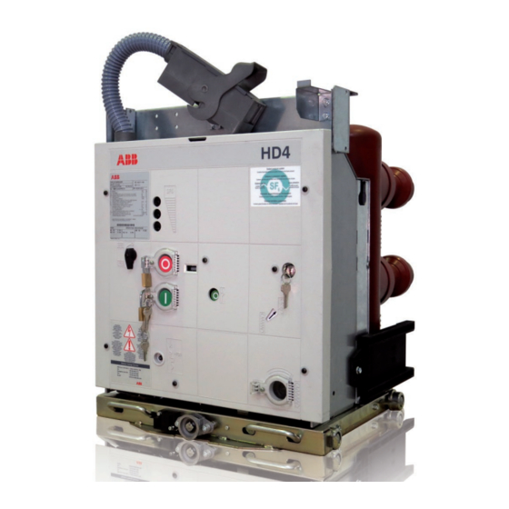
Page 10: Description
Description 5.1. General features 5.3. Fixed circuit-breaker The HD4 series are sulphur hexafluoride circuit-breakers for The fixed circuit-breaker (see fig. 4) corresponds to the basic indoor installation. For the electrical performance, please refer version complete with a front protection shield and frame. - Page 11 The strikers for activating the contacts (connected/isolated), The activating lever (connection/isolation) must be fully located in the enclosure or in the switchgear, are fixed in the inserted. A lock prevents the truck from advancing into the top part of the circuit-breaker. The slides for activating the enclosure or fixed part (for example when the earthing switch segregation shutters of the medium voltage contacts of the is closed).
-
Page 12: Instructions For Circuit-Breaker Operation
Instructions for circuit-breaker operation 6.1. Safety indications 6.3. Circuit-breaker closing and opening operations (fig. 6) HD4 circuit-breakers ensure a minimum degree of protection IP2X if installed under the following Circuit-breaker operation can be manual or electrical. conditions: – fixed version, with protection netting a) Manual operation for spring charging –... -
Page 13: Installation
Installation 7.1. General 7.4. Installation of fixed circuit-breaker The circuit-breaker can be mounted directly on the supporting Correct installation is of prime importance. The frames provided by the customer. instructions given by the manufacturer must be carefully studied and followed. It is good The circuit-breaker, complete with supporting truck, must be practice to use gloves to handle the pieces during fixed to the floor of its compartment with special brackets. - Page 14 7.6. Fixed circuit-breaker power circuit Mounting procedures connections – Place the connections in contact with the circuit-breaker terminals. 7.6.1. General directions – Interpose a spring washer and a flat washer between the head of the bolt and the connection. – The connections must be made using only the squares- –...
- Page 15 Standards in force. automatism provided for operation of the pressure switch (if provided) referring to the latest technical documentation supplied by ABB. 7.8.1. Fixed circuit-breaker The connection of the circuit-breaker auxiliary circuits must be made via the terminal box mounted on the circuit-breaker structure.
- Page 16 7.9. Overall dimensions Fixed circuit-breakers M12 depth 25 2XM8 depth 16 1VCD000226 336,5 13,5 67,5 1250 31.5 M12 depth 22 10,5 2XM8 depth 16 114,5 Fixed circuit-breakers 2XM8 depth 16 M12 depth 25 1VCD000231 336,5 13,5 67,5 17.5 1250 31.5 2XM8 depth 16 10,5 M12 depth 25...
- Page 17 Fixed circuit-breakers 7163 17.5 1600 Ø18 15.5 7163 17.5 2000 Ø 13 31.5 Ø 10.5 Fixed circuit-breakers 137.5 137.5 420 min. 7165 17.5 2500 3150 3600 31.5 7165 Ø18 Ø13 2500 Ø10.5 3150 3600 31.5 Insulating partitions (only for 24 kV) to be provided by the customer (a special kit is available on request).
- Page 18 7.9. Overall dimensions Fixed circuit-breakers 451,5 2XM8 depth 16 1VCD000235 M12 depth 25 356,5 13,5 103,5 103,5 67,5 1250 M12 depth 25 10,5 2XM8 depth 16 Insulating partitions to be provided by the customer (a special kit is available on request). Fixed circuit-breakers M12 depth 25 2XM8 depth 16...
- Page 19 Fixed circuit-breakers 7174 1600 31,5 Ø 7174 15.5 2000 31,5 Ø Ø 10.5 Fixed circuit-breakers with truck (on request) Ø 7241 1250 1600 Ø * Distance with truck (if provided). Ø Ø 10.5 363.5 695.4 Ø Ø 516.4...
- Page 20 7.9. Overall dimensions Fixed circuit-breakers with truck (on request) 7268 1250 1600 31.5 with truck (on request) 7268 2000 31.5 Insulating partitions to be provided by the customer (a special kit is available on request). * Distance with truck (if provided). Fixed circuit-breakers with truck (on request) 7315...
- Page 21 HD4/P withdrawable circuit-breakers for UniGear type ZS1 switchgears HD4/P 1VCD000227 17.5 1250 31.5 Also suitable for Power- Cube PB1 ±2...
- Page 22 7.9. Overall dimensions HD4/P withdrawable circuit-breakers for UniGear type ZS1 switchgears HD4/P 7350 ±1 ±1 111.5 17.5 1250 HD4/P 67.5 7350 17.5 1600 53.5 31.5 kA (*) kA (*) (*) Also suitable for PowerCube PB2. ±2 ±1.5 HD4/P withdrawable circuit-breakers for UniGear type ZS1 switchgears...
- Page 23 HD4/P withdrawable circuit-breakers for UniGear type ZS1 switchgears HD4/P 7352 kV (*) 111.5 ±1 ±1 17.5 2500 31.5 67.5 (*) Also suitable for PowerCube PB3. 43.5 ±2 ±1.5 HD4/P withdrawable circuit-breakers for UniGear type ZS1 switchgears HD4/P 7371 96.5 ±1 ±1...
- Page 24 7.9. Overall dimensions HD4/P withdrawable circuit-breakers for UniGear type ZS1 switchgears HD4/P ±1 ±1 1VCD00236 1250 kA (*) (*) 630 A only. ±1 ±2 ±1,5 HD4/P withdrawable circuit-breakers for UniGear type ZS1 switchgears HD4/P 1VCD000099 ±1 ±1 67.5 1250 A 31.5...
- Page 25 HD4/P withdrawable circuit-breakers for UniGear type ZS1 switchgears HD4/P 7355 (*) ±1 ±1 1600 A 31.5 67.5 (*) Also suitable for PowerCube PB5. 43.5 ±2 ±1.5 HD4/P withdrawable circuit-breakers for UniGear type ZS1 switchgears HD4/P 7356 (**) ±1 ±1 2000 A 31.5...
- Page 26 7.9. Overall dimensions HD4/W withdrawable circuit-breakers for PowerCube modules HD4/W 111,5 1VCD000228 17.5 1250 A 31.5 587 ±1,50 210 ±1 210 ±1...
- Page 27 HD4/W withdrawable circuit-breakers for PowerCube modules HD4/W 7421 ±1 ±1 17.5 1250 A 67.5 ±2 ±1.5 HD4/W withdrawable circuit-breakers for PowerCube modules HD4/W 7239 ±1 ±1 17.5 1600 A 2000 A 67.5 31.5 ±2 ±1.5...
- Page 28 7.9. Overall dimensions HD4/W withdrawable circuit-breakers for PowerCube modules HD4/W 1VCD000053 ±1 ±1 17.5 3150 A 31.5 67.5 43.5 ±2 ±1.5...
- Page 29 Withdrawable circuit-breakers HD4/W for UniGear type ZS2 switchgear and for PowerCube module HD4/W 7402 67.5 1250 A Withdrawable circuit-breakers HD4/W for UniGear type ZS2 switchgear and for PowerCube module HD4/W 7316 1250 A 31.5...
- Page 30 7.9. Overall dimensions Withdrawable circuit-breakers HD4/W for UniGear type ZS2 switchgear and for PowerCube module HD4/W 119 23 7317 67.5 1600 A 2000 A 2500 A (*) 31.5 (*) With forced ventilation. HD4/Z withdrawable circuit-breakers for UniGear type ZS3.2 - 40.5 kV switchgears HD4/Z/40.5 kV...
- Page 31 HD4/SEC withdrawable circuit-breakers for UniSec switchgears HD4/SEC 24 kV 625 ±1 1VCD000220 121,5 ±1 1250 687 ±1,5 210 ±1 210 ±1 19,5 DETAIL A SCALE 1 : 2...
-
Page 32: Putting Into Service
All the operations regarding putting into service – check the tightness of the power connections on the circuit- must be carried out by ABB personnel or customer breaker terminals; personnel who are suitably qualified and have – establish the setting of the direct solid-state overcurrent an in-depth knowledge of the apparatus and release (if provided);... - Page 33 Subject of the inspection Procedure Positive check Locking electromagnet on With the circuit-breaker open in the isolated for test position Connection is not possible. the circuit-breaker truck and the locking electromagnet not supplied, attempt to (YL2) (if provided). connect the circuit-breaker. Supply the locking electromagnet and carry out the Connection takes place correctly.
-
Page 34: Periodical Checking
Periodical checking 10. Maintenance operations Before carrying out any operation, make sure that Maintenance must only be carried out by ABB the operating mechanism springs are discharged personnel or in any case by suitably qualified and that the apparatus is in the open position. -
Page 35: Indications For Handling Apparatus With Sf6
Potential (GWP) which is 22.800 higher than CO2, according document (1VCP000264). to the Fourth Assessment Report. To dispose of the SF6 gas, please contact the ABB The GWP is calculated over a time period of 100-years Assistance Service (see contact persons at http://www.abb. -
Page 36: Spare Parts And Accessories
12.1. List of spare parts All assembly operations of spare parts/accessories regarding installation, putting into service, service – Shunt opening release and maintenance must be carried out by ABB – Additional shunt opening release personnel or suitably qualified customer personnel – Undervoltage release with in-depth knowledge of the apparatus (IEC –... - Page 38 For more information please contact: More product information: abb.com/mediumvoltage Your contact center: abb.com/contactcenters More service information: abb.com/service Data and illustration are not binding. We reserve the right to make changes in the course of technical development. © Copyright 2018 ABB. All rights reserved.