Table of Contents
Advertisement
Quick Links
Advertisement
Table of Contents

Related Manuals for Omicron CMC 356


Summary of Contents for Omicron CMC 356
- Page 1 CMC 356 Reference Manual...
- Page 2 The user is responsible for every application that makes use of an OMICRON product. OMICRON electronics translates this manual from the source language English into a number of other languages. Any translation of this manual is done for local requirements, and in the event of a dispute...
-
Page 3: Table Of Contents
Information for Disposal and Recycling ................. 12 1 Designated Use ......................13 2 Introduction ........................14 Options Available for the CMC 356 Test Set............. 14 3 Operating the CMC 356 ....................15 System Components....................15 Safe Use of the Connecting Cables ................16 3.2.1... - Page 4 CMC 356 Reference Manual Signal Generation......................28 4.2.1 Accuracy and Signal Quality................... 28 5 Connections and Interfaces ..................29 Front Panel Connections .................... 29 5.1.1 Generator Combination Socket for VOLTAGE OUTPUT and CURRENT OUTPUT..32 Connections on the Back Panel................. 34 5.2.1...
- Page 5 Table of Contents Inputs..........................60 6.4.1 Binary Inputs........................60 6.4.2 Counter Inputs 100 kHz (Low Level) ................63 Technical Data of the Communication Ports ............. 65 6.5.1 The NET-1C Board......................65 6.5.2 The NET-1B Board ......................66 6.5.3 The NET-1 Board ......................66 Environmental Conditions...................
- Page 6 Option LLO-2 (Low Level Outputs) ................94 7 Increasing the Output Power, Operating Modes ............95 Safety Instructions for High Current Output............. 95 Single-Phase Operation of the CMC 356 ..............96 7.2.1 1 x 32 A High Burden Mode (L-L-L-L) ................96 7.2.2...
-
Page 7: Preface
REFACE The purpose of this reference manual is to familiarize users with the CMC 356 test set and to show how to use it properly in various application areas. The manual contains important tips on how to use the CMC 356 safely, properly, and efficiently. -
Page 8: Safety Instructions
Before operating the CMC 356 test set, carefully read the following safety instructions. Only operate (or even turn on) the CMC 356 after you have read this reference manual and fully understood the instructions herein. The CMC 356 may only be operated by trained personnel. Any maloperation can result in damage to property or persons. - Page 9 Follow the instructions in sections 3.2 and 3.4 that describe the safe use of the connecting cables and how to set the CMC 356 into operation. • The CMC 356 must only be used from a power outlet that has a protective earth. •...
- Page 10 For applications drawing DC current: The load may not exceed 3 mH because of dangerous feedback current. • When setting up the CMC 356, make sure that the air slots on the back, top, and bottom of the test set remain unobstructed. •...
- Page 11 Safety Instructions Changing the Power Fuse • Unplug the power cord between the test set and the power source. • The fuse is located at the back of the test set. • Fuse type: T12.5 AH 250 V (wire fuse 5 × 20 mm). For safety reasons please use only fuse types recommended by the manufacturer.
-
Page 12: Information For Disposal And Recycling
CMC 356 Reference Manual NFORMATION FOR ISPOSAL AND ECYCLING Regulations for the EU and other European countries with corresponding laws The test set must not be disposed of in the household garbage. At the end of its service life, bring the test set to a collecting point for electrical recycling in accordance with the local legal regulations. -
Page 13: Designated Use
[0 Hz (DC) ... 10 kHz] for ten analog inputs are available. The CMC 356 is part of the OMICRON Test Universe which, in addition to the physical test set, consists of a test software for a computer with... -
Page 14: Introduction
CMC 356 Reference Manual NTRODUCTION The CMC 356 is a part of the OMICRON Test Universe which, in addition to the physical test set, consists of a test software for a computer with Microsoft Windows operating system, and, when needed, external voltage and/or current amplifiers, GPS or IRIG-B synchronization units or other accessories. -
Page 15: Operating The Cmc 356
System Components Before operating the CMC 356 for the first time, use the packing list to verify that all components of the test system are available. To set the CMC 356 into operation you need the following components: •... -
Page 16: Safe Use Of The Connecting Cables
↔ Safety socket of, for example, the CMC 356 test set. Plug only the regular test leads of 2.0 m/6 ft. length into the CMC 356 output safety sockets. Regular test lead Test lead adapter ↔... -
Page 17: Regular Test Leads For Safety Sockets
Operating the CMC 356 Regular Test Leads for Safety Sockets Use the regular test leads of 2.0 m/6 ft. length to connect the CMC 356 output to other safety sockets of, for example, amplifiers, test objects or to banana adapters in control cabinets. -
Page 18: M4 (0.15") Cable Lug Adapters
CMC 356 Reference Manual 3.3.2 M4 (0.15") Cable Lug Adapters The optional CMC Wiring Accessory Package includes M4 (0.15") cable lug adapters to connect regular test leads to screw-clamp terminals of SEL/ABB/GE relays (and others). Regular test lead ↔ M4 (0.15") cable lug adapter The cable lugs have blank ends. -
Page 19: Starting The Test System
Click Test Universe Software Manuals. In this topic you find a direct link at "Getting Started". To view the manual, click the link. This description refers both to the computer and to the CMC 356. It does not take into consideration any external devices. If the system is driven by external amplifiers, follow the instructions in section 7.5, "Operation with... - Page 20 “Technical Data of the Communication Ports” on page 76. For instructions how to incorporate network-capable CMC test sets like the CMC 356 into a computer network, refer to the Getting Started with Test Universe manual. To view the manual, start the Test Universe Help from the Start Page or any test module and navigate to the table of contents entry User Manuals (at the beginning of the table of contents).
-
Page 21: Setup And Function
Setup and Function ETUP AND UNCTION The computer-controlled OMICRON test system employs the concept of a functional division between the software running on the computer and the CMC 356 hardware connected to the test object. OMICRON Test Universe test software running on the computer •... -
Page 22: Block Diagram
1* Note regarding the hardware option ELT-1: The hardware option ELT-1 enables the measurement of analog signals using the CMC 356. In the standard configuration (CMC 356 without option ELT-1), the inputs BINARY/ANALOG INPUT 1 - 10 can only be used as... -
Page 23: Voltage Output (Voltage Amplifier)
(voltage outputs) The four voltage outputs have a common neutral N and are galvanically separated from all other outputs of the CMC 356. The two black sockets labeled "N" are galvanically connected with one another. The voltage amplifier and the current amplifiers are linear amplifiers with DC coupling. -
Page 24: Current Output (Current Amplifier)
The output sockets are internally protected against currents > 45A peak (32A ; the CMC 356 switches off with the error message "current on neutral too high"). In non-operative state, relay contacts (as illustrated in figure 5-3) protect the current amplifier from external power by shortening the outputs to N. -
Page 25: Binary / Analog Input (Binary Inputs 1 - 10)
CPU. The binary inputs are configured from the Hardware Configuration module of the OMICRON Test Universe software. When doing so, it can be specified whether the contacts are potential-sensitive or not. When the contacts are potential-sensitive, the expected nominal voltage and pick-up threshold can be set for each binary input. -
Page 26: Aux Dc (Dc Power For Test Objects)
"This unit outputs an AuxDC voltage of ___V immediately after powering-up". If the voltage on the "AUX DC" output exceeds 42 V, the associated signal light lights up. More information about the configuration of the AUX DC supply can be found in the OMICRON Test Universe AuxDC Help. -
Page 27: Cpu
Setup and Function 4.1.6 The CMC 356 CPU (Central Processing Unit) carries out the following tasks: • Communication with the computer or a network via USB or Ethernet. • Digital signal generation for all outputs of the test set (including control signals for external amplifiers). -
Page 28: Signal Generation
4.2.1 Accuracy and Signal Quality The CMC 356 is a very precise test set with excellent long-term and temperature drift behavior. To achieve this accuracy, the philosophy was not only to solve signal generation digitally, but also to implement the distribution of signals to the various modules using digital methods. -
Page 29: Connections And Interfaces
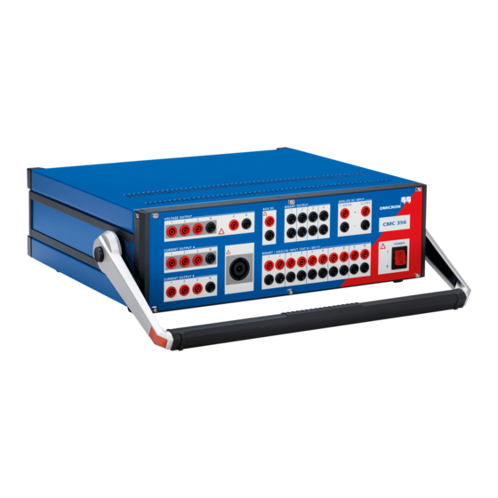
ONNECTIONS AND NTERFACES Front Panel Connections Figure 5-1: AUX DC Front view of the CMC 356 Output voltage in 3 ranges from 0 - 264 V; used to supply power to test objects. VOLTAGE OUTPUT BINARY OUTPUT ANALOG DC INPUT... - Page 30 Circuit diagram of a binary input with potential-free operation (dry) programmable threshold voltage (wet operation) Note: For simplified circuit diagrams of the inputs BINARY/ANALOG INPUTS and ANALOG DC INPUT of the CMC 356 with hardware option ELT-1 installed, please refer to Figure 6-19 on page 76.
- Page 31 Connections and Interfaces Figure 5-3: VOLTAGE OUTPUT Simplified diagrams of 4 x 300 V current and voltage outputs CURRENT OUTPUT A CURRENT OUTPUT B 3 x 32 A 3 x 32 A In non-operative state, relay contacts (as illustrated in figure 5-3) protect the current amplifier from external power by shortening the outputs to N.
-
Page 32: Generator Combination Socket For Voltage Output And Current Output
CURRENT OUTPUT The combination socket CURRENT OUTPUT / VOLTAGE OUTPUT simplifies the connection of test objects to the CMC 356. The three voltage outputs (VOLTAGE OUTPUT 1-3) as well as the CURRENT OUTPUT A are wired to the combination socket (refer to table 5-1 on page 33). - Page 33 VOLTAGE 2 and VOLTAGE 3 as well as CURRENT 2 and CURRENT 3. Table 5-2: Manufacturer ordering Description of the generator combination socket information Description SPEAKON LINE 8-pole Article Number NL8FC Manufacturer Neutrik (www.neutrik.com) You can order the plug for generator combination socket directly from OMICRON.
-
Page 34: Connections On The Back Panel
USB Port The test set’s standard interface NET-1C board holds a USB port to connect the CMC 356 to your computer. To ensure the required EMC compatibility, we strongly recommend to use the OMICRON-supplied cable, only. Note that a Test Universe software of version 3.0 (or later) plus the matching CMC firmware is required for the USB port to work. -
Page 35: Ethernet Ports Eth1 And Eth2
Connections and Interfaces 5.2.2 Ethernet Ports ETH1 and ETH2 The NET-1C board’s two PoE (Power over Ethernet) ports ETH1 and ETH2 are standard 10/100Base-TX (twisted pair) Ethernet ports. They support auto crossing (auto MDI/MDIX). This means you can use a standard cable or a cross-over Ethernet patch cable. -
Page 36: Status Led A, B
The test set will issue voltages and currents only when it is associated to the client requesting this. The association process can be initiated by the Test Set Association and Configuration tool or by the OMICRON Device Browser. For more details about this process, refer to the Help of the according tool. -
Page 37: Ethernet / Network Settings
OMICRON Test Universe. For instructions how to incorporate network-capable CMC test sets like the CMC 356 into a computer network, refer to the The First Steps to Get Started chapter of the Getting Started with Test Universe manual. -
Page 38: Selv Interfaces
For energy meter test applications, the "ext. Interf." grants easy connectivity. Synchronization Via the "ext. Interf.", the CMC 356 time base can be GPS- and IRIG-B- synchronized. Depending on the synchronization method of your choice, use either the CMGPS synchronization unit or the CMIRIG-B interface box. -
Page 39: Ll Out 1-6 (Low Level Outputs 1-6)
The low level outputs are short-circuit-proof and continually monitored for overload. Connect the external amplifier to the CMC 356 low level outputs. Use the connecting cable that was supplied with the amplifier. For more detailed information please refer to the technical data section 6.3.5, "Low Level Outputs "LL out"... - Page 40 CMC 356 Reference Manual...
-
Page 41: Technical Data
Technical Data ECHNICAL Guaranteed Values: • General: The values are valid for the period of one year after factory calibration, within 23 °C ± 5 °C at nominal value and after a warm-up time greater than 25 min. • Guaranteed values from the generator outputs: The values are valid in the frequency range from 10 to 100 Hz unless specified otherwise. -
Page 42: Insulation Coordination
Measurement category CAT III / 300 V (BINARY / ANALOG CAT IV / 150 V INPUTS) Functional groups on CMC 356 front panel: VOLTAGE OUTPUT, CURRENT OUTPUT (A, B), AUX DC, BINARY OUTPUT, BINARY / ANALOG INPUT, ANALOG DC INPUT... -
Page 43: Outputs
Technical Data Outputs For block diagrams of the available generator outputs, please refer to section 4.1, "Block Diagram" on page 22. Table 6-3: Analog current, voltage, General Generator Outputs Data and LL outputs. (analog current and voltage outputs, outputs "LL out") Frequency ranges sinusoidal signals 10 …... -
Page 44: Extended Frequency Range
Extended Frequency Range In selected Test Universe modules (e.g., Harmonics and PQ Signal Generator) the CMC 356 supports a mode for generating stationary signals up to 3 kHz on the voltage outputs and the low-level outputs. This mode corrects the phase and gain errors of the output filter. The 3 dB bandwidth of this filter limits the amplitude at 3 kHz to about 70 % of the maximum range value. -
Page 45: Current Outputs
Technical Data 6.3.2 Current Outputs Table 6-5: Outputs of current groups Current Outputs (Groups A and B) A and B Output currents 6-phase AC (L-N) 6 x 0 ... 32 A (Group A and B) Footnotes: 3-phase AC (L-N) 3 x 0 ... 64 A (Group A + B parallel) 1.Data for three-phase 2, 3 2-phase AC (L-L) - Page 46 S: 64A (L-L) [VA] 1400 P: 64A (L-L) [W] S: 128A (LL-LN) [VA] 1200 P: 128A (LL-LN) [W] 1000 Output Current [Arms] Output current in A For additional information refer to section 7.2, "Single-Phase Operation of the CMC 356" on page 96.
- Page 47 Technical Data Figure 6-3: Typical compliance 160.0 voltage (50/60 Hz) 140.0 low sensitive 32 A (L-L-L-L) 1~ low sensitive 32A (L-L-L-L) 120.0 high sensitive 32 A (L-L-L-L) 1~ high sensitive 32A (L-L-L-L) low sensitive 64 A (L-L//L-L) 1~ low sensitive 64A (L-L // L-L) high sensitive 64 A (L-L//L-L) 1~ high sensitive 64A (L-L // L-L) 100.0...
- Page 48 CMC 356 Reference Manual Figure 6-5: Typical continuous output current and output power at 23 °C; single-phase mode Current in A Figure 6-6: Typical continuous output current and output power at 23 °C; three- and six-phase mode Current in A The continuous operating range is given by the area below the curves in the figure 6-5 and 6-6 above.
- Page 49 Technical Data Table 6-6: Typical duty cycles for 6 x 32 A (L-N) 3 x 64 A (L-N) operation at ambient duty toff duty toff temperature of 23 °C cycle [min] cycle [min] 0 ... 25 0 ... 1200 100% >...
-
Page 50: Voltage Outputs
CMC 356 Reference Manual 6.3.3 Voltage Outputs Table 6-7: CMC 356 voltage outputs 4 Voltage Outputs Footnotes: Output voltages 1.a) V (t) automatically 3-phase AC (L-N) 3 x 0 ... 300 V calculated: 4-phase AC (L-N) 4 x 0 ... 300 V... -
Page 51: Power Diagram For Three-Phase Operation
Technical Data 6.3.3.1 Power Diagram for Three-Phase Operation Figure 6-7: typical Power diagram for three-phase operation guaranteed Output voltage in V... -
Page 52: Power Diagram For Single-Phase Operation
CMC 356 Reference Manual 6.3.3.2 Power Diagram for Single-Phase Operation Also refer to section 7.2.4, "Single-Phase Voltage" on page 99. Figure 6-8: typical Single-phase operation guaranteed Output voltage L-N in V Figure 6-9: Single-phase operation typical guaranteed Output voltage L-L in V... -
Page 53: Operational Limits In Conjunction With Mains Supply
Technical Data 6.3.4 Operational Limits in Conjunction with Mains Supply Principally, the maximum output power of the CMC 356 is limited by the mains input supply voltage. For mains voltages of 115 V or smaller, it is also possible to supply the CMC 356 with two phases (L-L) instead of the normal phase-neutral (L-N) operation in order to increase the supply voltage (115 V * sqrt(3) = 200 V). -
Page 54: Low Level Outputs "Ll Out" For External Amplifiers
In addition, each SELV interface connector provides a serial digital interface (pins 8-16; see below) that transmits control and monitor functions between the CMC 356 and the external amplifiers. Supported devices are the CMA 156, CMA 56 , CMS 156, CMS 251... - Page 55 GND is connected to protective earth (PE). Input OMICRON amplifier nominal: 0 ... 5 V If you purchased the option FL-6, the maximum output frequency is constrained to 599 Hz. Values at nominal voltage (10 V ), 50/60 Hz, and 20 kHz measurement bandwidth.
-
Page 56: Low-Level Binary Outputs ("Ext. Interf.")
< 3 µs (V = 5 V, R = 4.7 k extern pullup Connection Connector "ext. Interf." (CMC 356 rear side) Insulation Reinforced insulation to all other potential groups of the test equipment. GND is connected to protective earth (PE). - Page 57 Figure 6-11: Circuit diagram of Rear side "ext. Interf." binary of CMC 356 transistor outputs 11 = 5 ... 15 V extern Inside of CMC 356 pullup Ω 22 k 16 V Binary outputs 11 ... 14 "ext. Interf." Ω...
-
Page 58: Binary Output Relays
CMC 356 Reference Manual 6.3.7 Binary Output Relays Table 6-14: Data of binary output 4 Binary Output Relays (Binary Outputs 1-4) relays Type Potential-free contacts; software-controlled AC loading 300 VAC; I 8 A; P 2000 VA DC loading 300 VDC; I 8 A;... -
Page 59: Dc Supply (Aux Dc)
Technical Data 6.3.8 DC Supply (AUX DC) Table 6-15: DC Voltage supply DC Supply (AUX DC) AUX DC Voltage ranges 0 ... 66 V (max. 0.8 A) 0 ... 132 V (max 0.4 A) 0 ... 264 V (max. 0.2 A) Power Max. -
Page 60: Inputs
CMC 356 Reference Manual Inputs 6.4.1 Binary Inputs Note: If option ELT-1 is installed, only the general binary input data given in the following Table 6-16 are valid. For detailed information about the option ELT-1, please refer to section 6.11, "Option ELT-1" on page 71. - Page 61 Applies to positive voltage signal edge; value shown in % of reading (rd.) + % of upper range value (rg.) Refer to figure 5-2, "Simplified circuit diagrams of binary inputs and outputs (CMC 356 standard, without option ELT-1 installed)" on page 30.
- Page 62 The debounce function is placed after the deglitch function described above and both are realized by the firmware of the CMC 356 and are calculated in real time. The figure below illustrates the debounce function. On the right-hand side of the figure, the debounce time is too short.
-
Page 63: Counter Inputs 100 Khz (Low Level)
2 V Rise & fall times < 1 ms Max. input voltage ± 30 V Connection Socket "ext. Interf." (rear CMC 356) Insulation Reinforced insulation to all other potential groups of the test equipment. GND is connected to protective earth (PE). - Page 64 CMC 356 Reference Manual Figure 6-16: Rear side Circuit diagram of of CMC 356 +15 V "ext. Interf." counter inputs Inside of 1 and 2 CMC 356 Ω 22 k Counter inputs 1 & 2 "ext. Interf." Ω 100 k...
-
Page 65: Technical Data Of The Communication Ports
Technical Data Technical Data of the Communication Ports The first versions of the CMC 356 test sets were delivered with a NET-1 board that contained two different Ethernet ports: ETH1, a10/100Base-TX Ethernet port and ETH2, a 100Base-FX (optical fiber) Ethernet port. -
Page 66: The Net-1B Board
CMC 356 Reference Manual 6.5.2 The NET-1B Board Table 6-22: NET-1B: Ethernet ports ETH1/ETH2 Technical data of the NET-1B communication Type 10/100Base-TX (10/100Mbit, ports ETH1 and ETH2 twisted pair, auto-MDI/MDIX or auto-crossover) Connector RJ45 Cable type LAN cable of category 5 (CAT5) - Page 67 Technical Data Table 6-24: Technical data of the NET-1: Ethernet port ETH2 NET-1 communication port Type 100Base-FX (100Mbit, fiber, duplex) ETH2 Connector MT-RJ Cable type 50/125 µm or 62.5/125 µm (duplex patch cable) Cable length > 1 km (0.62 miles) possible Status idication Green LED: physical link present Yellow LED: traffic on interface...
-
Page 68: Environmental Conditions
(17.7 x 5.7 x 15.4 ") Housing IP20 according to EN 60529 Cleaning To clean the CMC 356, use a cloth dampened with isopropanol alcohol or water. Prior to cleaning, always switch off the power switch and unplug the power cord from the mains. -
Page 69: Safety Standards, Electromagnetic Compatibility (Emc) And Certificates
Technical Data Safety Standards, Electromagnetic Compatibility (EMC) and Certificates Table 6-28: CE conformity, certified Safety Standards and Emission EMC compatibility Europe EN 61326-1; EN 61000-6-4; EN 61000-3-2/3 International IEC 61326-1; IEC 61000-6-4; IEC 61000-3-2/3 FCC Subpart B of Part 15 Class A Immunity Europe EN 61326-1;... -
Page 70: Compliance Statements
CMC 356 Reference Manual 6.10 Compliance Statements 6.10.1 Declaration of Conformity (EU) The product adheres to the specifications of the guidelines of the council of the European Community for meeting the requirements of the member states regarding the electromagnetic compatibility (EMC) Directive 2004/108/EC, the low voltage Directive 2006/95/EC and the RoHS Directive 2011/65/EU. -
Page 71: Option Elt-1
Binary/analog inputs and inputs for analog DC measurement Binary/analog inputs The ELT-1 option enables the CMC 356 to measure analog signals: • Analog DC inputs (+/-10V and either +/-1mA or +/-20mA) for basic transducer testing with the test module QuickCMC. -
Page 72: General Data
CMC 356 Reference Manual Using the CMC 356 test set in combination with the Test Universe module Transducer enables advanced testing of multifunctional single-phase and three-phase electrical transducers with symmetrical or non-symmetrical operating characteristics. The hardware option ELT-1 can either be ordered with the new test set or later as a factory upgrade (the CMC 356 needs to be returned to OMICRON). -
Page 73: Analog Dc Input (Vdc, Idc)
Technical Data Four different operating modes are possible: • Multimeter Mode (section 6.11.6) • Harmonic Analysis (section 6.11.7) • Transient Recording (section 6.11.8) • Trend Recording (section 6.11.9) 6.11.2 Analog DC Input (V Figure 6-18: DC measurement unit (analog inputs V The measurement of analog DC signals has been implemented to enable the testing of transducers. -
Page 74: Accuracy Of The Analog Dc Input
CMC 356 Reference Manual 6.11.3 Accuracy of the Analog DC Input Note: Exceeding the specified input values can damage the measurement inputs! Table 6-29: DC measurement input DC Measurement Input IDC Measurement ranges 0 ... ±1 mA 0 ... ±20 mA Max. -
Page 75: Measuring Currents
Technical Data 6.11.4 Measuring Currents Since the analog inputs of the CMC 356 are voltage inputs, current measurement has to be performed using suitable active current clamps with voltage outputs or shunt resistors. OMICRON offers the C-PROBE1 as a suitable current clamp. The C-PROBE1 is not included in the scope of delivery of option ELT-1 and thus has to be ordered separately. -
Page 76: Accuracy Of Binary/Analog Inputs With Option Elt-1
CMC 356 Reference Manual 6.11.5 Accuracy of Binary/Analog Inputs with Option ELT-1 The technical data for the binary inputs change with the installation of option ELT-1. Figure 6-19: ANALOG DC INPUT Simplified diagrams of analog and binary inputs Only available with option ELT-1. -
Page 77: Multimeter Mode
Ω Input impedance 162 k (|| 50 pF) Refer to figure 5-2, "Simplified circuit diagrams of binary inputs and outputs (CMC 356 standard, without option ELT-1 installed)" on page 30. 6.11.6 Multimeter Mode This operating mode is designed for measuring steady-state signals (e.g., also non-sinusoidal shaped signals). -
Page 78: Accuracy Of Ac Measurements
CMC 356 Reference Manual 6.11.6.1 Accuracy of AC Measurements Conditions: integration time 1 s, measurement signal sinusoidal, excitation 10 - 100 %, accuracy references the measurement full scale values. Table 6-33: Sampling rate 28.44 kHz; Frequency range Accuracy measurement range... - Page 79 Technical Data The accuracy data contains linearity, temperature, long-term drift, and frequency. Figure 6-20: Typical frequency Frequency response in the 100 V range Frequency Response in the 100 V Range response with a sampling (SR = 28.44 kHz) (SR = 28.44 kHz) rate of 28.44 kHz and an Maximum+3Sigmamax input voltage of 70 V...
-
Page 80: Channel Cross-Talk
CMC 356 Reference Manual Figure 6-22: Typical AC linear AC linearity in the 100 V range AC Linearity in the 100 V Range progression at 50 Hz and a Maximum+3Sigmamax sampling rate of 0.04 Minimum-3Sigmamin 28.44 kHz 0.03 0.02 0.01 -0.01... -
Page 81: Accuracy Of Phase Measurement
Technical Data 6.11.6.3 Accuracy of Phase Measurement Figure 6-23: Phase error as function of Phase error as function of the input voltage Phase Error as a Function of the input voltage input voltage Phase CH1-CH2; range: 100 V; f = 50 Hz (Phase CH1-CH2, Range:100 V, f = 50 Hz) CH1:10V CH1:70V... -
Page 82: Sampling Rate
CMC 356 Reference Manual Figure 6-25: Typical phase error as Phase error as function of input frequency Phase Error as a Function of Frequency function of the input (fs = 28.44 kHz, range = 100 V, Uin = 20 Vrms) (SR = 28.44 kHz, R: 100 V, Uin = 20 Vrm s) -
Page 83: Accuracy Of Frequency Measurement
Technical Data 6.11.6.4 Accuracy of Frequency Measurement Figure 6-26: Error in the frequency Error in frequency measurement as a function of the input voltage Error in Frequency Measurem ent as a Function of the input voltage measurement as a (measured over 50 periods) (Measured over 50 Periods) function of the input voltage... -
Page 84: Accuracy Of Power Measurement
CMC 356 Reference Manual 6.11.6.5 Accuracy of Power Measurement General The power is calculated from one current channel and one voltage channel: Active power: * u t ( )*i t ( ) t d -- - Apparent power: S = V... - Page 85 Technical Data Table 6-43: Sampling rate Frequency range Power Accuracy 9.48 kHz Typical Guaranteed 10 Hz ... 750 Hz + 0.3 % / - 0.7 % ± 1.8 % 10 Hz ... 750 Hz + 0.3 % / - 0.7 % ±...
- Page 86 CMC 356 Reference Manual Typical relative error as function of the excitation Figure 6-27: Typical error of the Typical error of apparent power S as function of the excitation Typ. Error apparent pow er S as a function of the excitation apparent power S as (fs = 28.44 kHz, f = 50 Hz)
- Page 87 Technical Data Figure 6-29: Typical error of the Typical error of reactive power Q as function of the excitation Typ. Error reactive pow er Q as a function of the excitation reactive power Q as a (fs = 28.44 kHz, f = 50 Hz) (fs = 28.44kHz, f=50Hz) function of the excitation, fs = 28.44 kHz, fin = 50 Hz...
-
Page 88: Harmonic Analysis
CMC 356 Reference Manual Note: • For very small phase shifts (< 0,3 °) and small excitation (< 10 %), too small integration time (< 1 s) or sampling rate 3.16 kHz, the sign of the reactive power cannot definitely be determined. -
Page 89: Accuracy Of Frequency Measurement
Technical Data 6.11.7.1 Accuracy of Frequency Measurement The permitted input frequency range depends on the specified sampling rate: Table 6-46: Sampling rate and input Sampling rate Input frequency range frequency range 28.44 kHz 49 Hz ... 3400 Hz 9.48 kHz 17 Hz ... -
Page 90: Accuracy Of Amplitude Measurement
CMC 356 Reference Manual 6.11.7.2 Accuracy of Amplitude Measurement The measurement values are given as effective values (rms). The permitted input frequency range for the fundamental wave depends on the specified sampling rate: Table 6-47: Sampling rate and input Sampling rate... -
Page 91: Accuracy Of Phase Measurement
Technical Data Table 6-51: Sampling rate Frequency range Accuracy 9.48 kHz Typical Guaranteed 3.16 kHz measurement range fmin ... 100 Hz ± 0.15 % ± 0.4 % 100 mV fmin ... 1 kHz ± 0.2 % / - 0.5 % ±... -
Page 92: Transient Recording
Trigger delay (negative) Recording of input signals Note: More details about triggering methods can be found in the OMICRON Test Universe Help and in the practical examples of the ELT-1 option. The maximum length of the recording depends on the settings for the... -
Page 93: Trend Recording
Technical Data Table 6-53: The maximum recording Number of Maximum Maximum Maximum time depends on the active recording time [s] recording time [s] recording time [s] number of active channels channels at fs = 28.4 kHz at fs = 9.48 kHz at fs = 3.16 kHz and the sampling frequency... -
Page 94: Option Llo-2 (Low Level Outputs)
CMC 356 Reference Manual 6.12 Option LLO-2 (Low Level Outputs) The LLO-2 option ("LL out 7 - 12") represents an additional SELV (SELV = Safety Extra Low Voltage) interface connector holding two independent generator triples. These six high accuracy analog signal sources can serve to either control an external amplifier or to directly provide small signal outputs. -
Page 95: Increasing The Output Power, Operating Modes
The CMC 356 has a very large application diversity. The current outputs offer enough output power to test all electromechanical relays. In particular, the CMC 356 offers a variety of types of single-phase operation using its two galvanically separated three-phase current outputs with which the output power from the units can be significantly increased. -
Page 96: Single-Phase Operation Of The Cmc 356
CMC 356 Reference Manual Single-Phase Operation of the CMC 356 7.2.1 1 x 32 A High Burden Mode (L-L-L-L) 1 x 0 ... 32 A (±45 A ), max. 140 V , 1 x 1740 VA at 25 A peak Both amplifier groups CURRENT OUTPUT A and CURRENT OUTPUT B are connected in series. -
Page 97: X 64 A High Burden And High Current Mode (L-L)
Increasing the Output Power, Operating Modes 7.2.2 1 x 64 A High Burden and High Current Mode (L-L) 1 x 0 ... 64 A (±90 A ), max. 70 V , 1 x 1740 VA at 50 A peak The currents 1 and 2 of each group are phase-opposite. In addition, the groups A and B are connected in parallel. -
Page 98: X 128 A High Current Mode (Ll-Ln)
CMC 356 Reference Manual 7.2.3 1 x 128 A High Current Mode (LL-LN) 1 x 0 ... 128 A (±180 A ), max. 35 V , 1 x 1000 VA at 80 A peak Since the current over the N socket is limited to 32 A... -
Page 99: Single-Phase Voltage
Increasing the Output Power, Operating Modes 7.2.4 Single-Phase Voltage 1 x 0 ... 300 V, 1 x 200 VA [100 ... 300 V] typical Figure 7-4: Single-phase operation of Load the voltage system (L-N) 1’ N’ 1 x 0 ... 600 V, 1 x 275 VA [200 ... 600 V] typical Figure 7-5: Single-phase operation of Load... -
Page 100: Two-Phase Operation
CMC 356 Reference Manual Two-Phase Operation For some applications it is beneficial to have two independent currents, each higher than 32 A , or a higher compliance voltage available. 7.3.1 2 x 64 A High Current Mode (LL-LN) 2 x 0 ... 64 A (±90 A ), max. -
Page 101: X 32 A High Burden Mode (L-L)
Increasing the Output Power, Operating Modes 7.3.2 2 x 32 A High Burden Mode (L-L) 2 x 0 ... 32 A (±45 A ), max. 70 V , 2 x 870 VA at 25 A peak The currents 1 and 2 of each group are phase-opposite. Observe the safety instructions given in Section 7.1 on page 95 when using this operating mode. -
Page 102: Three-Phase Current Mode With High Burden
CMC 356 Reference Manual Three-Phase Current Mode with High Burden 3 x 0 ... 32 A (±45 A ), max. 70 V , 3 x 860 VA at 25 A peak For loads with three separate phases it is possible to double the available compliance voltage. -
Page 103: Operation With External Amplifiers
6 × 250 V / 75 VA for the synchronization in two galvanically separated voltage triples with CMC 356 + CMS 156. For a complete overview of the supported configurations of the CMC 356 and CMA/S amplifiers see the OMICRON Test Universe Help, topic... - Page 104 CMC 356 Reference Manual...
-
Page 105: Troubleshooting
Troubleshooting ROUBLESHOOTING Troubleshooting Guide In case of operational problems with the CMC 356 proceed as follows: 1. Consult the reference manual or the Test Universe Help. 2. Check whether the malfunction is reproducible and document it. 3. Try to isolate the malfunction by using another computer, test set or connecting cable, if available. -
Page 106: Potential Errors, Possible Causes, Remedies
CMC 356 Reference Manual Potential Errors, Possible Causes, Remedies Some potential disruptions that may occur while operating the CMC 356 are listed below. Try to eliminate them by applying the remedies proposed here. Table 8-1: Troubleshooting the Error Possible causes... -
Page 107: Open Source License Information
OURCE ICENSE NFORMATION Parts of the CMC test set software are under OMICRON license, other parts are under open source software licenses. Both the open source license texts and the necessary source code are provided in the OMICRON Open Source Download Area at www.omicron.at/opensource/. - Page 108 Open Source License Information...
-
Page 109: Support
OMICRON Academy – Learn More www.omicron.at/academy www.omicronusa.com/academy Learn more about your product in one of the training courses offered by the OMICRON Academy. OMICRON electronics GmbH, Oberes Ried 1, 6833 Klaus, Austria, +43 59495... - Page 110 Support...
-
Page 111: Index
DC current measurement input ......... 74 max. altitude for operation ........68 DC measurement (ANALOG DC INPUT) ....74 amplifier current amplifier (output) of CMC 356 ....24 DC voltage measurement input ......... 74 voltage amplifier (output) of CMC 356 ....23 debouncing input signals ........... 62 apparent power calculation .........84... - Page 112 ............43 output drift ............43 output range settings ...........43 output resolution ..........43 front panel components of CMC 356 ......29 LL out (SELV low level outputs) ......... 54 fuse changing the fuse ..........11 LLO-2 option .............. 94 type ..............41...
- Page 113 GPS ........... 38 output error ..........45 synchronized operation ..........43 output range ............43 output resolution ..........43 system components of CMC 356 ......15 PoE (Power over Ethernet, technical data) ....65 power active power calculation ........84 apparent power calculation ........84 reactive power calculation ........84...
- Page 114 ........69 USA/Canada Federal regulations ..........70 USB on NET-1C board (technical data) ......65 vibration ..............68 voltage max. input voltage INPUT VDC ......74 voltage outputs (technical data) ........50 weak mains supply and output power (relation) ..53 weight of CMC 356 .............68...
Need help?
Do you have a question about the CMC 356 and is the answer not in the manual?
Questions and answers