Omicron CPC 100 User Manual
Hide thumbs
Also See for CPC 100:
- Reference manual (382 pages) ,
- User manual (78 pages) ,
- Getting started (23 pages)
Table of Contents
Advertisement
Quick Links
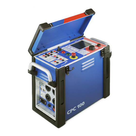
CPC 100
User Manual
Preface
Introduction
Manual Information
Article Number VESD0601 - Manual Version: CPC100LITE.ENU.11
With respect to the functionality of the CPC 100 software, this manual refers to the version
V 3.20.
© OMICRON electronics 2014. All rights reserved.
This product includes software developed by Intrinsyc Software.
This manual is a publication of OMICRON electronics GmbH.
All rights including translation reserved. Reproduction of any kind, for example, photocopying,
microfilming, optical character recognition and/or storage in electronic data processing systems,
requires the explicit consent of OMICRON electronics. Reprinting, wholly or in part, is not
permitted.
The product information, specifications, and technical data embodied in this manual represent
the technical status at the time of writing and are subject to change without prior notice.
We have done our best to ensure that the information given in this manual is useful, accurate
and entirely reliable. However, OMICRON electronics does not assume responsibility for any
inaccuracies which may be present.
The user is responsible for every application that makes use of an OMICRON product.
OMICRON electronics translates this manual from the source language English into a number
of other languages. Any translation of this manual is done for local requirements, and in the
event of a dispute between the English and a non-English version, the English version of this
manual shall govern.
Current
Voltage
Transformer
Transformer
Others
Common
Functions
Support
When you are working with our products we want to provide you with the greatest possible
benefits. If you need any support, we are here to assist you!
24/7 Technical Support – Get Support
www.omicron.at/support
www.omicronusa.com/support
Offering our customers outstanding support is one of our top priorities. At our technical support
hotline, you can reach well-educated technicians for all of your questions. Around the clock –
competent and free of charge.
Make use of our 24/7 international technical support hotline: +43 59495 4444.
Additionally, you can find our Service Center or Sales Partner closest to you at
or www.omicronusa.com.
Customer Area – Stay Informed
www.omicron.at/customer
www.omicronusa.com/customer
The customer area on our website is an international knowledge exchange platform. Download
the latest software updates for all products and share your own experiences in our user forum.
Browse through the knowledge library and find application notes, conference papers, articles
about daily working experiences, user manuals and much more.
OMICRON Academy – Learn More
www.omicron.at/academy
www.omicronusa.com/academy
Learn more about your product in one of the training courses offered by the OMICRON
Academy.
OMICRON electronics GmbH, Oberes Ried 1, 6833 Klaus, Austria, +43 59495
www.omicron.at
Advertisement
Table of Contents

Related Manuals for Omicron CPC 100


Summary of Contents for Omicron CPC 100
- Page 1 When you are working with our products we want to provide you with the greatest possible benefits. If you need any support, we are here to assist you! With respect to the functionality of the CPC 100 software, this manual refers to the version V 3.20.
- Page 2 Do not turn on or use the CPC 100 if you do not format on the CPC 100 Toolset CD-ROM and the CPC 100 Start Page. However, it does not understand the information in this manual.
- Page 3 ► Make sure that a test object’s terminals that are to be connected to the CPC 100 do not carry Note: Any other use of the CPC 100 but the one mentioned above is considered improper use, any voltage potential.
- Page 4 “banana” connectors and plastic housing or, where applicable, with the especially ► Instead of supplying the CPC 100 from phase - neutral (L1-N, A-N), it may also be supplied manufactured counterpart supplied by OMICRON electronics (e.g., for the V2 AC hazardous.
- Page 5 The CP TD1 works as an add-on device to the CPC 100 and is described in chapter ► Ground the test object, and disconnect it from the CPC 100. By disconnecting it, you prevent ”CP TD1”...
- Page 6 I / 0 warning lights indicate either a safe operation, i.e., no voltage at the CPC 100 outputs (green light “0” on), or an operation with possibly hazardous voltage and /or current levels at the CPC 100 outputs (red light “I” on or flashing).
- Page 7 Functional Components of the CPC 100 High-Voltage and Current Outputs 1. For detailed information on the RJ45 connectors, see chapter “CPC 100 in a Network” in the DANGER CPC 100 Reference Manual available in PDF format on the CPC 100 Toolsets or CPC 100...
- Page 8 Ext. Booster The term “focus” designates the currently selected (active) part of the test card. The selected The CPC 100 software comprises a number of test cards. A test card carries out one specific Rectifier component is highlighted or inverted.
- Page 9 Test Procedure Overview The CPC 100 File System The highest hierarchical level of the CPC 100 file system, the “root”, is named CPC 100. Below Note: The file containing the up-to-date measurements should be saved regularly. If the test unit this, you can create additional folders in a tree-structure of your choice, save tests in these is switched off, or in case of a power outage, all unsaved measurements will be lost.
- Page 10 Clipboard. Proceed with Paste… the folder tree, but the one that is currently open. Set current clamp Select the test of your choice. Press Copy to copy test or folder to the CPC 100 parameters and CT and/or Submenu File clipboard.
- Page 11 Set date and time. Regional setting for language, temperature unit, date and time style. These settings affect the way the CPC 100 software displays and sort dates, times, numbers and decimal points. DHCP / Auto-IP Complete the steps below to set the...
- Page 12 With the exception of Quick, pressing an accelerator key opens the corresponding Insert a new test card dialog box and lets you select the test card of your choice. Pressing Quick opens the During operation, the CPC 100 creates a log file with a user-definable logging level. Quick test card directly.
- Page 13 CPC 100 V 3.20 Introduction - 8 Introduction...
- Page 14 Settings Page Measuring with Quick Quick is the most basic mode to operate all of the CPC 100 outputs in a manual-like mode with If the output quantities of the selected output can be measured, the combo boxes “1 measured Pressing the Settings menu key opens the Settings page.
-
Page 15: Trigger Settings
/ phase angle data entry field. on measurements. This synchronizes the CPC 100 output frequency with the V1 AC input frequency (we recommend a minimum input voltage of 10 V on V1 AC, possible range 48 - Indicates the signal 62 Hz). - Page 16 Current Transformer CPC 100 V 3.20 CTRatio (and Burden) CTRatio (with Burden) - The Option Measure Burden Use the CTRatio test card to measure a current transformer’s ratio and burden with injection on Select the check box Measure Burden to measure the burden in VA.
- Page 17 CTRatio (with Burden) - The Option Measure Burden CTBurden Additional measurements when Measure Burden is selected: This is the preferred method in cases, when the current of max. 800 A that the CPC 100 can feed into the CT’s primary side is not sufficient. Secondary...
- Page 18 CPC 100 V 3.20 CTExcitation (Knee point) Use the CTExcitation test card to record the excitation curve of a current transformer. This test The graph displays the test results in form of an interpolated curve with test point markers. Maximum test voltage performs an automatic injection of a test voltage of up to 2 kV to the current transformer’s...
- Page 19 ► Check whether the red warning light “I” and the discharge LED are off before results are disconnecting the device under test. considered stable if Dev < 0.1 %. ► Before disconnecting from the CPC 100, connect the device under test on both Measured voltage ends to protective earth. at input V DC Transformer’s...
- Page 20 To do so, the CPC 100 injects a special polarity test signal at a certain location. This signal can Death or severe injury caused by high voltage or current polarity as OK, and lights up the green LED.
- Page 21 CPC 100 V 3.20 Polarity Check CTRatioV (with Voltage) Select the option Intermittent to save power in the 800A AC output range and define a pulse The preferred method for CT ratio measurement is current injection using the CTRatio test card.
- Page 22 Select to stop test frequency I nominal) via an integrating amplifier or fed into an electronic protection relay with integrator. The automatically when CTRogowski test card integrates the Rogowski coil’s output signal at the CPC 100’s V2 AC measurement is Measured done input.
- Page 23 CPC 100 V 3.20 CTRogowski CTLowPower (Ratio) Use the CTLow Power test card to measure the ratio of a low-power current transformer with a Nominal secondary voltage of Rogowski coil Nominal frequency built-in burden and an output voltage that is directly proportional to the primary current.
- Page 24 The Merging Unit (MU) converts the sensor output analog into an SV stream which is published to the substation network. The CPC 100 then reads the Channel data back from the network in order to perform a variety of different tests.
- Page 25 CPC 100 V 3.20 Current Transformer - 10 Current Transformer...
- Page 26 To do so, open the circuit as shown in the figure below, and inject the AC voltage from the ► Do not connect the CPC 100 output to the secondary side of the VT. This will cause CPC 100’s 130V AC output into the burden. Input I AC measures the current that flows into the hazardous voltages on the primary side burden, and input V1 AC the voltage at the burden.
- Page 27 130V AC output Use current clamp rather than input I AC red LED green LED Actual voltage at The CPC 100 injects a the burden Select to enter special polarity check measured at input polarity checker secondary current signal...
- Page 28 CPC 100 V 3.20 VTElectronics Use the VTElectronics test card to test the ratio of non-conventional electronic voltage transformers with a very low-level secondary voltage. Correction factor for Nominal primary voltage V prim Electronic protection relay with 3 and 1/3: Correction factors for V sec...
- Page 29 CPC 100 V 3.20 Voltage Transformer - 4 Voltage Transformer...
- Page 30 Death or severe injury caused by high voltage or current of the table ► Do not connect the CPC 100 output to the secondary side of the transformer. This will cause hazardous voltages on the primary side Transformer - 1...
- Page 31 CPC 100 V 3.20 Settings Page Automatic Tap Fill TRRatio (per Tap) The Settings page of the TRRatio test card offers an offline Auto-tap fill function. It The following table shows the V prim and V sec settings on the TRRatio test card for different automatically fills in the nominal ratio table of the TRRatio test card for symmetric tap changers.
- Page 32 CPC 100 V 3.20 TRRatio (per Tap) Yz11 v/X2 U-(V+W) / H1- u-w / X1-X3 1*√3/2 V/H2 V/H2 u/X1 U-(V+W) / H1- w-u / X3-X1 √3/2 V/H2 w/X3 u/X1 U-V / H1-H2 v-u / X2-X1 (H2+H3) (H2+H3) w/X3 w/X3 U/H1 W/H3...
- Page 33 Death or severe injury caused by high voltage or current During the Vector Group Check, the CPC 100 continuously puts out the set test voltage. ► Do not touch the CPC 100’s outputs and do not touch or unplug any cables. Transformer - 4 Transformer...
- Page 34 Auto-tap is selected. DANGER Death or severe injury caused by high voltage or current Time required for ► Connect the CP SA1 discharge box to the CPC 100's V DC input sockets. switching between two taps NOTICE...
- Page 35 (OLTC) current recommended Winding connection switches without interruption. to use the Reference temperature The CPC 100 injects a constant current Actual test CP SA1 for Actual specimen from the 6A DC output into the power current this test.
- Page 36 Taps may show quite different results depending Note: If the CPC 100 is in Auto Keep Result status, the user can end the process by either on the direction of the tap movement and defects can behave differently. An interruption pressing Keep Result or by changing to the Tolerance setting and changing the value.
- Page 37 Measured current DANGER The CPC 100 Demag test card requires a Test current Never touch or unplug the CP SB1 transformer switch box. The wiring cables before the automatic is the same as for a standard resistance Demag cycle is completed.
- Page 38 Resistance CPC 100 V 3.20 µ Measurement The Resistance test card provides a total of three output ranges. The test setup depends on 10 m to 10 to 20 k the selected range. ...
- Page 39 V DC 2 wire) done DANGER Death or severe injury caused by high voltage or current ► Connect the CP SA1 discharge box to the CPC 100’s V DC input sockets. NOTICE Highest possible Equipment damage caused by high voltage or current...
- Page 40 Measuring the Ground Resistance of Small Ground Systems Measuring the Ground Resistance of Large Ground Systems system and a remote auxiliary electrode. To measure the earth resistance, the CPC 100 injects AC current between the substation’s ground system and a temporary remote auxiliary electrode.
- Page 41 Note: To learn how to measure the resistance of a single ground rod in an earthing system, refer to the CPC 100 Reference Manual, section “RGround” of chapter “Resistance”. The CPC 100 Reference Manual is available in PDF format on the CPC 100 Toolsets or the...
- Page 42 ***) This option can lead to a freeze of the CPC 100 caused by a memory overflow. This can happen if there are too much results in a certain time. In this case, the CPC 100 can only be switched off via the Emergency Stop button. The CPC 100 Switch off on trigger, i.e., abort sequence when the trigger condition becomes true...
- Page 43 Current values < 50A do not initiate an "Overload" when the current *) State 2 and 4 incl. the additional 100 ms the CPC 100 adds to compensate for the debounce The actual value for CB close equals 477 ms - 100 ms = 377 ms.
- Page 44 Others: Ramping CPC 100 V 3.20 General Use the Ramping test card to define a series of ramps to be applied to a connected test object. The feature Manual Trigger provides a possibility to manually initiate a trigger A series of up to 5 ramps can be defined. The ramps within that series execute sequentially, and signal (i.e., a premature termination) of the current ramp at any time.
- Page 45 152.35A. "frozen" for 1 s. The CPC 100’s AC OUTPUT feeds the ramped current signal into a CT, which is connected to an overcurrent relay. The overcurrent relay’s trip contact is fed into the CPC 100’s binary input BinIn, and acts there as a trigger signal.
- Page 46 Others: Amplifier CPC 100 V 3.20 General Use the Amplifier test card to set the CPC 100 to an "amplifier-like" mode. In this mode, an Starting a high-current output Display of the measured high-current input signal fed into a synchronization input drives the high-current output’s magnitude,...
- Page 47 This example shows how the three current outputs of a CMC 256-3 test set are led to the synchronization inputs I AC of three CPC 100 test sets to drive their high-current outputs. This way, the CPC 100 high-current outputs represent the "amplified" CMC 256-3 outputs and, in this example, are connected to three CTs.
- Page 48 Others: Comment CPC 100 V 3.20 Starting the String Editor Form Editor - Text Editor The Comment card is inserted to a test procedure in the same manner like a test card. Its To create such a "2 columns" layout use the Form Editor.
- Page 49 Others: HV Resonance Test System CPC 100 V 3.20 General Test Settings The HV Resonance Test System test card is used for generic high-voltage tests on GIS with To set the test cycle: Nominal CT ratio a resonance circuit in combination with the CP RC1 or the CP RC2.
- Page 50 Common Functions CPC 100 V 3.20 Test Assessment The test assessment is a manual procedure carried out by the user. The String Editor is used to name or rename test cards, tests and templates as well as to fill out Important special characters the Comment card.
- Page 51 CPC 100 V 3.20 The String Editor The Template Phrases The String Editor provides a feature, that allows you to save phrases, i.e., names of test cards, tests, templates, folders and files. Once these phrases are saved, they can then be selected as template phrases from the Select a phrase combo box.
- Page 52 Note: For detailed information refer to the section “Technical Data” in the CPC 100 Reference Range Guaranteed accuracy Amplitude Power Typical accuracy Manual available in pdf format on the CPC 100 Toolsets or the CPC 100 Start Page. Output Range Amplitude Phase Amplitude...
- Page 53 +/- 0.50 % higher. V DC 100 mV 0.10 % 0.20 % 0.05 % 0.10 % 10 mV 0.10 % 0.30 % 0.05 % 0.15 % CPC 100 Technical Data - 2 CPC 100 Technical Data...
-
Page 54: Resistance Measurement
Safety EN 61010-1, EN 60950, IEC 61010-1, produced and tested in < 5 mA 10 k 0.50 % 1.00 % an EN ISO 9001 certified company. Prepared for IEEE 510, EN 50191, VDE 104 CPC 100 Technical Data - 3... - Page 55 Weight and Dimensions Weight 29 kg (64 lbs), case without protection cover Dimensions W x H x D: 468 x 394 x 233 mm (18.4 x 15.5 x 9.2"), cover, without handles. CPC 100 Technical Data - 4 CPC 100 Technical Data...
- Page 56 ► Tighten the plugs manually. Do not use any tools for that because that can damage the plugs or connectors. The CP TD1 works as an add-on device to the CPC 100. Do not connect the CP TD1 to any other device. Do not use the accessories for applications not indicated in this User Manual.
- Page 57 If the CPC 100 and CP TD1 are to be operated without trolley, place them on their transport the high voltage to the cases and connect them with the long type data cable CPC 100 CP TD1 (3 m) and the long- test object type booster cable CPC 100 ...
- Page 58 7. Switch on the CPC 100. 8. Selecting the TanDelta test card from any of the CPC 100’s CT, VT, Transformer or Others test card groups automatically turns on the CP TD1. If no CP TD1 is connected to the CPC 100, an error message appears.
- Page 59 Once these values were measured, enter them into the respective entry fields of delivered with the CP TD1 or available in pdf format on the CPC 100 Start Page. measured and then compared to the known reference values.
- Page 60 CP TD1 TanDelta-PF Test Card - Main Page The TanDelta-PF test card can be accessed from CT, VT, Transformer and Others test card “Auto test points” cleared = manual measurement: Applies the set test voltage and Measuring modes and their according groups.
- Page 61 "use default frequency of xx.xx Hz" is not specifically selected. If selected, the CPC 100 checks whether the shield of the high-voltage cable is connected. For ± 5 Hz means that interferences at frequencies with an offset of ± 5 Hz from the measuring some large inductive loads, the CPC 100 can accidentally report shield check error even when frequency will not affect the results.
- Page 62 CP TD1 CP TD1 High-Voltage Source Test Settings In addition to the Dissipation Factor (TanDelta)/Power Factor test, the CP TD1 can also be used Define automatic test cycle Set maximum voltage Show minimum Show maximum inductance as a high-voltage source for measuring, for example, partial discharge or conducting high- inductance possible possible with available voltage tests on rotating machines.
- Page 63 CP TD1 Technical Data of the CP TD1 in Combination with the CPC 100 High-Voltage Output Filter for selective measurements Capacitance Cp (equivalent parallel circuit) Conditions: f0 = 15 … 400 Hz Conditions: Signals below 45 Hz with reduced values possible. Capacitive linear loads.
- Page 64 CP TD1 Technical Data of the CP TD1 in Combination with the CPC 100 Phase angle Power P, Q, S (selective) Weight and dimensions Weight Dimensions (W x H x D) Range Resolution Typical accuracy Conditions Range Resolution Typical accuracy...
- Page 65 CP TD1 CP TD1 - 10 CP TD1...
-
Page 66: Block Diagram
► Use the CP GB1 grounding box to connect the CP CU1 to overhead lines and power cables. ► Set the current range switch on the CP CU1 front panel only when the CPC 100 is turned For detailed information, see the application-specific “Safety Instructions for Connecting off and the test object is grounded. - Page 67 If the arc persists for a longer short-circuit bar time period, the surge arrestor insulator melts and the terminals are short-circuited to ground, V1 AC output thereby protecting the operating staff, CP CU1 and CPC 100. To CP CU1 To test object Surge arrestor...
- Page 68 Death or severe injury caused by high voltage or current ► Only set the current range switch on the CP CU1 front panel when the CPC 100 is turned off and the test object is connected to ground with closed grounding switch near the measurement setup.
- Page 69 Connecting the CPC 100 and CP CU1 to Power Lines Start with the 100 A current range. Is the line longer than Is the value greater than Are 60 A possible? 2 km/1.5 mi? Line Length × 2 × 0.4/km (0.64/mi) × I...
- Page 70 CPC 100 Start Page. For detailed information on the CP CU1 applications, refer to the CP CU1 Reference Manual delivered with the CP CU1 or available in pdf format on the CPC 100 Start Page. Far end Far end...
- Page 71 100 … 250 V 20 … 10 A 20 A I AC V2 AC I AC I OUT CPC 100 CP CU1 25 … 300 0.3 … 1.0 % 0.5 … 1.5° 250 … 500 V 10 … 1.5 A...
- Page 72 (this means the test object) still "feeds" voltage potential ► Even if you switched off the CPC 100, wait until the red I/O warning light is fully extinguished. back into the 6A DC output.
- Page 73 ► Make sure to measure the voltage to ground at the terminals of the tap changer. If no voltage • DC input for connection to the 6A DC output and I AC/DC input of the CPC 100 is measured, connect the flexible terminal adapters to the "up" and "down" terminals of the •...
-
Page 74: Technical Data
I continuous = 0.9 A rms 15 g / 11 ms, half-sinusoid, 3 shocks in each axis Supply Via serial interface from the CPC 100 (+15 V) EN 61326-1 Class A Overvoltage protection to case with All connections to Tranformer High and Low voltage... - Page 75 CP SB1 CP SB1 - 4 CP SB1...
- Page 76 2000 A mode: 1000 A mode: The output current of the CPC 100 can be increased up to 2000 A by means of an electronically controlled current booster. The CP CB2 can be connected close to the busbar using short high- current cables and to the CPC 100 with a long control cable.
- Page 77 DANGER Death or severe injury caused by high voltage or current Internal measurement of outputs ► Do not touch the CPC 100’s outputs and do not touch or unplug any cables while Guaranteed accuracy Typical accuracy working with the CP CB2.
Need help?
Do you have a question about the CPC 100 and is the answer not in the manual?
Questions and answers