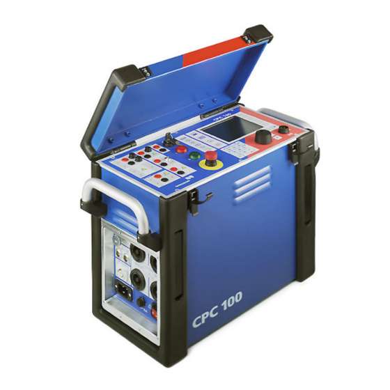
Omicron CPC 100 Reference Manual
Multi-functional primary test system for substation commissioning and maintenance
Hide thumbs
Also See for CPC 100:
- User manual (78 pages) ,
- Getting started (23 pages) ,
- Reference manual (370 pages)
Table of Contents
Advertisement
Quick Links
Download this manual
See also:
User Manual
Advertisement
Chapters
Table of Contents

Related Manuals for Omicron CPC 100


Summary of Contents for Omicron CPC 100
- Page 1 CPC 100 Reference Manual PRIMARY TEST SYSTEM FOR SUBSTATION EQUIPMENT COMMISSIONING AND MAINTENANCE Accessories included...
- Page 2 Reference Manual are not contractually binding. OMICRON electronics reserves the right to make changes at any time to the technology and/or configuration without announcement. OMICRON electronics is not to be held liable for statements and declarations given in this Reference Manual.
-
Page 3: Table Of Contents
Safety Instructions for CPC 100 and its Accessories ....... 1-5... - Page 4 Principle Steps to Carry Out a Test with CPC 100 ......2-47...
- Page 5 Voltage Withstand Test ........... . . 4-25 Test Settings.
- Page 6 CPC 100 V1.41 Test Settings............5-14 Measurements .
- Page 7 The CPC 100 File System ........
- Page 8 OMICRON Device Browser ........
- Page 9 General ..............15-1 Installation of the Excel CPC 100 File Loader Software ......15-1 Computer Requirements .
- Page 10 PC and Network Interfaces (CPC 100 V0 only) ....... 16-29...
- Page 11 Polarity Checker CPOL ........... . . 17-9 Technical Data of CPOL .
- Page 12 CPC 100 V1.41...
-
Page 13: Preface
CPC 100 must be used in observance of all existing safety requirements from national standards for accident prevention and environmental protection. Reading the CPC 100 manual alone does not release the user from the duty of complying with all national and international safety regulations relevant for working with CPC 100, for example, the regulation EN50191 "Erection and... -
Page 14: Glossary Of Symbols And Terms
CPC 100 V1.41 The Reference Manual always has to be available at the site where CPC 100 is used. It should be read and used by all people working with CPC 100. In addition to the Reference Manual and the applicable regulations for accident prevention in the country and at the site of operation, the accepted technical procedures for safe and competent work should be heeded. -
Page 15: Used Terms
DHCP Dynamic Host Configuration Protocol; used to connect CPC 100 to a PC network (refer to ”CPC 100 in a Network” in chapter 11). embedded Personal Computer, that is, fully-functional PC with processor, RAM, interfaces, operating system etc. that is embedded into CPC 100. - Page 16 16-2.) sel = frequency-selective measurement (see page 3-6) Test object The object to be tested by CPC 100, for example, a current or voltage transformer. Trigger A trigger is an "initiator". In this case it is an electrical signal, for example, at CPC 100 binary input, whose occurrence causes direct follow-up actions, such as switching off the output signals.
-
Page 17: Safety Instructions For Cpc 100 And Its Accessories
Principle Use According to Regulations • CPC 100 should only be used in a safe manner, mindful of the dangers while paying attention to the Reference Manual, and when it is in a technically sound condition and when its use is in accordance with the regulations. In particular, avoid disruptions that could in turn affect safety. -
Page 18: Operator Qualifications And Primary Responsibilities
If you have a cardiac pacemaker, do not use CPC 100! Before operating DANGER! CPC 100, make sure there is no person with a cardiac pacemaker in the immediate vicinity. Never use CPC 100 without a solid connection to ground with at least 6mm². -
Page 19: General
• Make sure that a test object’s terminals that are to be connected to CPC 100 do not carry any voltage potential. During a test, the only power source for a test object may be CPC 100. -
Page 20: Dc Output To Test Objects With A High Inductance
CPC 100 V DC input sockets when using the 400A DC output to protect yourself and CPC 100 from high-voltage hazards. If a test object with a big inductance was connected to CPC 100, short-out the test object additionally before disconnecting it from CPC 100. -
Page 21: High-Voltage And High-Current Outputs
This is a physical and an electrical hazard. – The red warning light on the CPC 100 front panel indicates hazardous voltage and/or current levels at the CPC 100 outputs (red light "I" on or flashing). The green warning light indicates that the CPC 100 outputs are not activated. - Page 22 • Opening CPC 100 invalidates all warranty claims. • If CPC 100 or any add-on device or accessory does not seem to function properly, do not use it anymore. Please call the OMICRON hotline. FOR YOUR OWN SAFETY Always follow the 5 safety rules: 1.
-
Page 23: Changing Fuses
CPC 100. • Locate the blown fuse on the front panel of CPC 100, and replace it: – 6.3A T (6.3 Amps slow-acting wire fuse 5x20mm) for AC OUTPUT in 6A operation mode or for DC OUTPUT. -
Page 24: Cpc 100 In Combination With Cp Td1
CP TD1 works as an add-on device to CPC 100 and is described at ”CP TD1” in chapter 9” of this manual. On principle, the safety instructions that apply to CPC 100 and its accessories also apply to CP TD1. -
Page 25: Designated Use
Preface Designated Use CPC 100, in conjunction with its accessories or as a stand-alone unit, is a multi- purpose primary test set for commissioning and maintaining substation equipment. It performs current transformer (CT), voltage transformer (VT) and power transformer (TR) tests. Furthermore it is used for contact and winding resistance testing, polarity checks as well as primary and secondary protection relay testing. - Page 26 This way, test reports, for example, can be loaded onto this PC and customized in standard applications. • CPC 100 provides a "dead man" function, that is the possibility to install an additional push-button that stops remote operation if released (refer to ”ePC Interfaces” on page 2-4).
-
Page 27: Cpc 100 Versions
× × × × 1. CPC 100 V1 units are equipped with one socket for connecting CPC 100 to both a PC and a network hub. For detailed information on the ePC interfaces, see ”ePC Interfaces” on page 2-4. 1 - 15... - Page 28 CPC 100 V1.41 1 - 16...
-
Page 29: Introduction
Test Procedure Overview ............page 2-31 File Operations................. page 2-32 Options..................page 2-33 Creating Defaults and Templates ..........page 2-42 Putting CPC 100 into Operation............ page 2-46 Principle Steps to Carry Out a Test with CPC 100 ....page 2-47 2 - 1... -
Page 30: Functional Components Of Cpc 100
6A DC output Note: With the CPC 100 V0, the number of test cards in one test procedure should be limited to 15 to avoid memory problems. The CPC 100 V1 allows using more test cards in one test procedure but we recommend not to use more than 15 test cards or more than 50 test results to keep the tests clearly structured. -
Page 31: High-Voltage And High-Current Outputs
Introduction High-Voltage and High-Current Outputs When CPC 100 outputs high current, observe the allowed duty cycles that may apply to the selected AC output range. For more information please refer to ”CPC 100 Outputs” on page 16-5. Figure 2: High-voltage and high-... -
Page 32: Epc Interfaces
Connector for external safety functions (see item 3 below) 1. For more information on the PC and network interfaces, see ”CPC 100 in a Network” on page 11-1. 2. For the pin assignment of the RS232 serial interface connector, see ”ePC Interfaces”... - Page 33 (see item 3 above) connecting optional CP TD1 test set (see item 2 above) The CPC 100 V1 supports the USB interface 1.1 and 2.0 for connecting the USB memory stick shipped with the CPC 100. Note: The full functionality is guaranteed only for the stick delivered with the CPC 100.
-
Page 34: Functional Components In Detail
The 3.15A T (3.15 Amps slow-acting wire fuse 5x20mm) protects the AC OUTPUT in 130V voltage mode and in the 3A AC current mode. 2. The 800A output sockets are situated at the left-hand side of CPC 100 as shown on page 2-3. - Page 35 It is highly recommended not to exceed the typical duration time t specified for each current and voltage output (refer to ”CPC 100 Outputs” on page 16-5). If you do, and CPC 100 develops too high an internal temperature, the outputs are shut off automatically.
- Page 36 AC OUTPUT group) protects both the AC OUTPUT in 6A current mode and the DC OUTPUT. 2. The 400A output is situated at the left-hand side of CPC 100 as shown at ”High-Voltage and High-Current Outputs” on page 2-3.
- Page 37 Introduction INPUT Analog precision measuring inputs Figure 7: 1. IAC/DC current measuring input 10A AC and DC Functional group INPUT Measuring input for AC and DC current of 0...10A, depending on the selected test card. AC current is measured in a frequency range of 15...400Hz. For both AC and DC current measurement, the software changes automatically between the two measuring ranges 1A and 10A.
- Page 38 Safety Key Lock To enable CPC 100 entire functionality, put the key into the safety key lock and turn it horizontally to the right (as shown in Figure 9). In the "enable" position two effects are differentiated: Figure 9: 1.
- Page 39 Introduction Warning lights The warning lights indicate either a safe or dangerous operating condition. Figure 10: Warning lights Dangerous operating condition! safe operating condition 1. Outputs are Green warning light Safe operating switched OFF (0) on condition 2. Output was selected Red signal lamp (I) Dangerous voltage by the software,...
- Page 40 Socket to connect an external booster, for example, the CP CB2 current booster for output currents of up to 2000A. Enable any external booster in the CPC 100 software on the tab Options | Device Setup (refer to ”Device Setup” on page 33 of this chapter).
-
Page 41: Cpc 100 Block Diagram (Simplified)
Introduction CPC 100 Block Diagram (Simplified) Figure 12: Simplified block Ext. diagram of CPC 100 Booster Rectifier & power factor 500V corrector 500V 500V 4A 500V 1kV 2A Switched 2kV 1A mode 500V amplifier Mains 100-240V Filter 50/60Hz 130V / 6A AC 800A 3.15A... -
Page 42: Built-In Epc
Via the built-in ePC, CPC 100 can be accessed from a stand-alone PC, for example, a notebook, via a PC network and via the Internet (refer to ”CPC 100 in a Network” in chapter 11). - Page 43 Introduction LCD monitor The monitor is a high-contrast gray-scale graphical LCD display with a resolution of 320x240 pixels. Accelerator keys Let you add the test card of your choice, for example, Quick, CT, VT... etc. (refer to ”Accelerator Keys” on page 22 of this chapter). View Selector Lets you select the view of your choice, for example, Test Card View, Test Procedure Overview, File Operations or Options (refer to ”View Selector”...
- Page 44 If the test parameters are set in the software’s Test Card View, the Emergency Stop button is released and the safety key lock is set to the "enable" position, pressing this push-button enables CPC 100 outputs and starts a test. Pressing this push-button a second time stops the test.
-
Page 45: How To Use The Cpc 100 Software
The principles of test cards and test procedures • Test cards The CPC 100 software comprises a number of test cards. A test card carries out one specific test, for example, measuring a CT excitation curve, or testing the ratio of a voltage transformer. - Page 46 - after the test was run - test results and assessments can be saved. It is then considered a report. Such a report can later be opened any time in CPC 100 File Operations menu.
- Page 47 Introduction Figure 14: The principles of test Test Card in Test Card View: Test Card Default cards, defaults and test procedures settings settings Test Card Test Card settings + Test results Test Card Test Procedure = Test in Test Procedure Overview: Default Procedure settings...
-
Page 48: Starting The Software
CPC 100 V1.41 Starting the Software When CPC 100 is switched on, the operating system boots up, and the CPC 100 software starts automatically. During the hardware and software initialization phase, the software displays a splash screen. The CPC 100 software starts in the Test Card View loading the test procedure default (refer to ”The principles of test cards and test procedures”... -
Page 49: View Selector
Introduction View Selector Figure 15: View selector Test Card View (default view upon start-up) View to set up test cards, compose test procedures, enter test settings, define test cards or the test procedure default, start tests etc. Test Procedure Overview Provides an enhanced overview of all test cards of the currently active test procedure. -
Page 50: Accelerator Keys
CPC Explorer CD-ROM). Test Card View The Test Card View displays the test procedures. The CPC 100 software starts in the Test Card View loading the test procedure default. A test card inserted to the Test Card View loads the values from the respective test card default. -
Page 51: Inserting Test Cards
Introduction The Test Card View comprises a number of context-dependent menu keys. Some examples are given below: Inserts a test card of your choice and places it after the selected test card of the current test procedure. Deletes the current test card from the test procedure. Opens the String Editor. - Page 52 Note: With the CPC 100 V0, the number of test cards in one test procedure should be limited to 15 to avoid memory problems. The CPC 100 V1 allows using more test cards in one test procedure but we recommend not to use more than 15 test cards to keep the tests clearly structured.
-
Page 53: Setting Up A Test Card
Introduction Setting Up a Test Card Each parameter whose numerical value can be changed in a data entry field has an associated minimum and maximum value as well as a preset number of decimal characters. The parameter value can be changed freely within this min. - Page 54 CPC 100 V1.41 Figure 17: Soft-touch keys to enter : backspace numerical values Esc: cancels the current Soft-touch keys to action without saving enter numerical — : prefix for negative values. values, for example, angles N T E R Decimal point...
- Page 55 Introduction List Box Figure 18: Example of a list box List boxes are differentiated between read-only and editable list boxes: • In a read-only list box (Figure 18), turning the handwheel scrolls from line to line. When using the U keys, a read-only list box is treated as one UI O W N element, that is, pressing one of the keys exits the list box, and sets the focus...
-
Page 56: Settings Page
CPC 100 V1.41 Settings Page Some test cards include the S menu key. Pressing the S E T T I N G S E T T I N G S menu key opens the Settings page. Figure 19: Main page with... -
Page 57: Starting A Test
Pressing the I/O (test start/stop) push-button starts the test. Pressing this push-button a second time stops the test. Note: Stopping a test does not shut off the CPC 100 outputs instantaneously. First, the currently running test sequence finishes, then the test execution is stopped. -
Page 58: Temperature Monitoring
In addition, if an output is activated, both CPC 100 current consumption from the power supply and the current emitted at the high-current outputs is monitored and, together with the temperature, displayed by this temperature gauge. The temperature gauge’s bar therewith represents an indicator for the remaining... -
Page 59: Test Procedure Overview
E F A U L T save the current test procedure as the test procedure default, that is the default the CPC 100 software will start with in future. To learn more about defaults, refer to section ”Creating Defaults and Templates”... -
Page 60: File Operations
For CPC 100 V1 units with a USB memory stick plugged in, a second tree root USB Disk is displayed as shown above. -
Page 61: Options
The Device Setup tab in the Options view allows you to change the settings of all test cards of the test procedure running on CPC 100 and all test cards inserted afterwards. The test cards can be instantiated in different ways and for different purposes. - Page 62 CPC 100 V1.41 Figure 22: Options tab Device Setup External booster The "External booster" combo box allows to set the external booster: • CB2 for CP CB2 current booster • CU20 for CP CU20 coupling unit • CU1 for CP CU1 coupling unit For the default value associated with different instantiation procedures, see Table 1: ”Instantiation procedures”...
- Page 63 Introduction Disable ground check Operating CPC 100 with the "Disable ground check" check box selected can cause injury or possibly death of the operating staff if the power supply is not metallically separated and the PE (protective connection) is defective.
- Page 64 Restore Defaults Pressing the R menu key resets all user-specific settings E S T O R E D E F A U L T S made in the CPC 100 software to factory-defined defaults including: • the test card defaults •...
- Page 65 Section ”CPC 100 in a Network” in chapter 11 explains in detail how to connect CPC 100 to either a stand-alone PC or a PC network, and how to configure such a connection. Once the communication parameters are configured, press S...
- Page 66 CPC 100 V1.41 Display Figure 24: Options tab Display The "sliding" regulator brightens or darkens the monitor display and the contrast within it. Adding contrast increases the difference in shading between areas. Date / Time Figure 25: Options tab Date/Time Specify the system’s date and time here.
- Page 67 During operation, CPC 100 creates a log file with a user-definable logging level (see below). Every time CPC 100 is switched on, it generates a new log file, and saves the existing one as the "previous" log file. This way, the occurrences of the previous and the current session can be viewed (refer to ”Viewing the log file”...
- Page 68 This setting is suggested if the operator suspects, for example, an incorrect functioning or an operational malfunction of CPC 100. This setting records every relevant operational activity of CPC 100. The log file can then be sent to OMICRON for diagnosis. The default setting is "Warning". Note: The logging levels are hierarchical, that is, if logging level "Warning"...
- Page 69 OS Version: operating system with version Software Version: CPC 100 software version Hardware: CPC 100 hardware The last two positions indicate the CPC 100 hardware version. Free memory: currently available free memory (RAM) Free disk space: free disk space 2 - 41...
-
Page 70: Creating Defaults And Templates
Note: A test card default contains user-defined settings, not test results. In the CPC 100 file system, a test card default is not visible as a "file" (refer to ”The CPC 100 File System” in chapter 9). 2 - 42... - Page 71 (refer to ”Test Procedure Templates” on page 45 of this chapter). In the CPC 100 file system, the test procedure default is not visible as a "file" (refer to ”The CPC 100 File System” in chapter 9). 2 - 43...
- Page 72 Step 1 In the test card view, insert as many test cards as needed to the currently open test procedure default. Step 2 At the CPC 100 front panel view selector, switch to the Test Procedure Overview. Step 3 Press S...
- Page 73 A test procedure template is a user-defined test procedure, and can be created from any test procedure that was saved to the CPC 100 file system beforehand (a name.xml file; refer to ”The CPC 100 File System” in chapter 9).
-
Page 74: Putting Cpc 100 Into Operation
– If there is a longer distance between the location of CPC 100 and the area of danger (that is, the test object), a second person with an additional "Emergency Stop"... -
Page 75: Principle Steps To Carry Out A Test With Cpc 100
3. Connect CPC 100 to the mains power supply using the provided cable. 4. With the test object grounded and shorted out, connect CPC 100 to the test object according to your requirements. 5. Remove the grounding set from the test object. - Page 76 After turning off the high voltage or current observe the warning lights: only when CPC 100 green warning light is on and the red one off, switch off the safety key lock and take off its key. 13.After turning off CPC 100 outputs, earth-connect and short-circuit the test object’s terminals again using a grounding set.
-
Page 77: Getting Started With Quick
Power Output Settings ..............page 3-7 Trigger Settings................page 3-11 About Quick Quick is the most basic mode to operate all of the CPC 100 outputs in a manual- like mode with front panel control. Figure 1: Quick test card CPC 100 starts in the Test Card View (refer to ”Test Card View”... - Page 78 After having set all necessary parameters (more about this in the following sections), press the I/O (test start/stop) push-button. The Quick test card enters the "on" state, the set power output value is switched to the CPC 100 outputs, the measuring continues.
-
Page 79: Measurement Settings
Getting Started with Quick Measurement Settings ⇒ Measured quantities ( Glossary) Combo boxes to select the first and second quantity to measure. Possible choices at each combo box: • V1 AC • I Out • V1 AC sel • I Out sel •... - Page 80 CPC 100 V1.41 Table 1: Display of calculated value in measurement Measured Display of calculated value in table quantities measurement table (m1) (m2) Ratio:1, Ratio:5, Diff: ϕ ϕ Ratio m1/m2 and phase angle m1 - (if phase angles are available; else "n/a"), Δ...
- Page 81 Getting Started with Quick Measured Display of calculated value in quantities measurement table (m1) (m2) Rs, Ls or Rp, Cp: Resistance R and either inductance Ls in H (series equivalent circuit) or capacity Cp in F (parallel equivalent circuit). This is just another representation of the impedance Z measurement;...
-
Page 82: The Frequency-Selective Measurement
The Frequency-Selective Measurement The frequency-selective measurement is used to filter out interferences as they usually occur in substations. To do so, the frequency of the CPC 100 output quantity is set to a value different from the substation’s frequency, for example, the substation operates with a frequency of 50Hz, the CPC 100 output frequency is set to 55Hz. -
Page 83: Power Output Settings
Getting Started with Quick Power Output Settings The main settings are the range definition and the value for the power output (the ⇒ data entry field in Figure 3 that has the focus ( Glossary)). The power output value can be changed instantaneously with the handwheel, even in the "on"... - Page 84 CPC 100 V1.41 Range Combo box to select between the output ranges AC 800A, AC 6A, AC 3A, DC 400A, DC 6A, AC 2kV, AC 1kV, AC 500V, AC 130V and CB2:1000A, CB2:2000A or CU20:10A, CU20:20A or CU1:10A, CU1:20A, CU1:50A, CU1:100A...
- Page 85 Getting Started with Quick Power output value Current (I) or voltage (V) value, depending on the specified range (see above). Any value between minimum and maximum as well as the explicit value 0.0 is possible, even while in the "on" state.
- Page 86 This synchronizes the CPC 100 output frequency with the V1AC input frequency. In this case the phase angle of the output is displayed rather than the frequency. Set...
-
Page 87: Trigger Settings
Selection of trigger event – no trigger (default) – binary trigger = CPC 100 input BIN IN is monitored for a trigger event – trigger = first measurement value (m1) > set threshold value – trigger = first measurement value (m1) < set threshold value –... - Page 88 BinIn. trigger signal with falling edge occurred at BinIn Delay time display The delay time is the time between the last change of the CPC 100 output value and the occurrence of the trigger event. 3 - 12...
- Page 89 E E P E S U L T S 1. Enabled When the trigger event occurs, the CPC 100 outputs are switched off immediately (that is, in real-time). The measurements are updated to show the values at the time the trigger event occurred, and are then "frozen", that is, not updated anymore from that moment...
- Page 90 CPC 100 V1.41 3 - 14...
-
Page 91: Current Transformer
With regard to software handling, this section confines to test-relevant issues, and does not go into detailed procedural descriptions. It is assumed that you have read and understood the section ”How to Use the CPC 100 Software” on page 2-17. 4 - 1... -
Page 92: Scope Of Current Transformer Tests
CPC 100 V1.41 Scope of Current Transformer Tests Go to the Test Card View and press I N S E R T A R D Use the context-dependent U menu keys to the right, or the O W N handwheel, to browse through the structure. On CT, press E N T E R Alternatively, press the accelerator key to open Insert a new test card. -
Page 93: Ct Ratio (And Burden)
Current Transformer CT Ratio (and Burden) Testing Ratio, Polarity (and Burden) with Injection to Current Input Use the CTRatio test card to measure a current transformer’s ratio and burden with injection on the CT’s primary side with up to 800 A from the 800A ACoutput or up to 2000 A using the CP CB2 current booster connected to the "EXT. - Page 94 CPC 100 V1.41 Test settings Figure 3: CTRatio test card with test results Navigate to the parameter fields, and enter the values according to your test requirements: Range: output range Iprim: nominal primary current Isec: nominal secondary current Itest: primary injection current.
- Page 95 3. by selecting the check box "Manual input". This option lets you enter the value for Isec manually, for example, when Isec was measured with an external current clamp that is not connected to CPC 100. Note: Select "Manual input" prior to starting the test. If the test card still...
- Page 96 CPC 100 V1.41 The "Measure burden" option Select the check box "Measure Burden" to measure the burden in VA. Note: This option is only useful as long as the injected current Itest is about of the magnitude of the nominal current Iprim.
- Page 97 Current Transformer Figure 5: CTRatio test card with selected "Measure burden" option and test results Additional measurements when "Measure burden" is selected Vsec: measured secondary voltage and phase angle relative to Iprim Burden: burden in VA: Isec nom × (Vsec act × Isec nom/Isec act) ϕ...
- Page 98 CPC 100 V1.41 Manual test Clearing "Auto" lets you set the test current Itest manually with the handwheel. – Press the I/O (test start/stop) push-button to start the test. The focus is set onto the "I test:" entry field. – Set the value of your choice either by turning the handwheel and/or by entering it with the numerical keys.
- Page 99 Current Transformer 2. Option "Manual input" selected Note: Select "Manual input" prior to starting the test. If the test card still contains results, clear them by pressing C L E A R E S U L T S When "Manual input" is selected, there is no phase available. ϕ...
-
Page 100: Testing Ratio, Polarity (And Burden) With A Current Clamp
CPC 100 V1.41 Testing Ratio, Polarity (and Burden) with a Current Clamp To measure Isec, a current clamp can be connected to, for example, the IAC/ DC current measuring input (as shown in Figure 6). Note 1: If a current clamp is used to measure Isec, select the corresponding check box on the test card, and specify the current clamp at the Options tab Device Setup (recommended) or on the Settings page. -
Page 101: Ct Burden
From these measurements, the burden (in VA) and the power factor cos calculated. This is the preferred method in cases when the current of max. 800A that CPC 100 can feed into the CT’s primary side is not sufficient. Figure 7: Setup for a CT burden... -
Page 102: Test Settings
CPC 100 V1.41 Test settings Figure 8: CTBurden test card with test results Navigate to the parameter fields, and enter the values according to your test requirements: Isec: nominal secondary current Itest: secondary injection current from 6A AC output output frequency... -
Page 103: Automatic Test Vs. Manual Test
Current Transformer Automatic Test vs. Manual Test 1. Option "Manual input" clear Automatic test – Press the I/O (test start/stop) push-button to start the test. The test current increases in a ramp characteristic from 0A to Itest within 1 second. Then Itest is kept and injected for a period of 2.4 seconds, the measurements are taken. - Page 104 CPC 100 V1.41 2. Option "Manual input" selected Note: Select "Manual input" prior to starting the test. If the test card still contains results, clear them by pressing C L E A R E S U L T S When "Manual input" is selected, there is no phase available.
-
Page 105: Ct Excitation (Kneepoint)
Current Transformer CT Excitation (Kneepoint) Use the CTExcitation test card to record the excitation curve of a current transformer. This test performs an automatic injection of a test voltage of up to 2kV to the current transformer’s secondary side. Figure 9: Setup for recording a CT excitation curve 4 - 15... -
Page 106: Test Settings
CPC 100 V1.41 Test Settings Figure 10: Blank CT Excitation test card – Navigate to the parameter fields for "Imax:", "Vmax:" and "f:", and enter the values according to your test requirements. – Select check box "Auto" for automatic test (default), clear it for manual test (refer to page 4-17). -
Page 107: Automatic Test Vs. Manual Test
Current Transformer Automatic Test vs. Manual Test Automatic test Selecting "Auto" increases and decreases the test voltage in a ramp characteristic, and places test points in an adaptive way to determine the knee point. – Press the I/O (test start/stop) push-button to start the test. The range from Vmin to Vmax is swept through, which is indicated by the crosshair cursor in the graphics. - Page 108 CPC 100 V1.41 – Press R to clear all points at once. This does not terminate the E M O V E test but lets you set new test points. – Once all test points are set, press the I/O (test start/stop) push-button to stop the manual test.
-
Page 109: Demagnetization
Current Transformer Figure 12: CT Excitation test card - using the crosshair cursor The final step of the test is the test assessment. To learn more about test assessment, refer to ”Test Assessment” on page 10-2. Demagnetization Both direct currents (DC) or unsymmetrical AC currents (for example, asymmetries when the CT is switched off) can cause a residual induction in CT cores. -
Page 110: Winding Resistance
Never open the measuring circuit while current flows. Dangerous voltage may occur! Check whether the red warning light “I” and the discharge LED are off before disconnecting the device under test. Before disconnecting from CPC 100, connect the device under test to protective earth. Figure 13: Setup for a winding... - Page 111 To do so, open the circuit as shown in Figure 13, and inject DC current from the CPC 100 6A DC output into the transformer’s secondary winding. Currents higher than 6 A are not needed for measuring CTs.
-
Page 112: Test Settings
CPC 100 V1.41 Test settings Figure 14: RWinding test card with test results Navigate to the parameter fields, and enter the values according to your test requirements: Range: output range (Use the 6A DC output for measuring CTs.) Itest: nominal test current R min: calculated minimum winding resistance value (display only). -
Page 113: Measurements
Current Transformer Measurements IDC: actual test current from 6A DC output or 400A DC output VDC: voltage that IDC generates at the transformer’s secondary winding, measured at V DC input R meas: transformer’s winding resistance, calculated from VDC / IDC Time: total elapsed test time Dev:... -
Page 114: The "Temperature Compensation For Cu" Option
CPC 100 V1.41 The "Temperature Compensation for Cu" Option Option selected Provides two more parameters to enter: Tmeas: ambient temperature Tref: operating temperature of test object, that is, the current transformer’s secondary winding Depending on these two parameters, the reference resistance (Rref,... -
Page 115: Voltage Withstand Test
Current Transformer Voltage Withstand Test Note: Some test cards are available in more than one test mode. For example, the test card VWithstand can be selected in CT, VT, Resistance and Transformer. This is solely related to usability. With regard to functionality, the test card VWithstand is identical in all test modes. -
Page 116: Test Settings
CPC 100 V1.41 Test Settings Figure 16: VWithstand test card with test results Navigate to the parameter fields, and enter the values according to your test requirements: Vtest: nominal test voltage (2kV max.) output frequency Time: time span Vtest is applied to the output Option "Switch off on IAC>... -
Page 117: Measurements
Current Transformer Measurements VAC: injected voltage from 2kV AC output at the time the test turned IAC: measured current between the transformer’s primary and secondary windings at the time the test turned off Imax: maximum measured current between primary and secondary winding during the entire test cycle Once all settings are defined, press the I/O (test start/stop) push-button to start the test. -
Page 118: Polarity Check
To do so, CPC 100 injects a special polarity test signal at a certain location. This signal can either be a voltage or a current signal from CPC 100, and has a signal characteristic similar to a saw-tooth signal with a different steepness for the rising and the falling slope. - Page 119 Remedy: increase the signal magnitude. Note: If you detect a wrong polarity in the current path, turn off CPC 100 first, and only then disconnect the terminals. If you are not quite certain whether your measurement is correct, you can confirm it by reversing the probes of CPOL.
-
Page 120: Test Settings
AC output range. The allowed pulse duty cycle, that is, the typical time , depends on the selected range, the ambient temperature, the operating conditions of CPC 100 etc. For more information please refer to ”CPC 100 Outputs” on page 16-5. 4 - 30... -
Page 121: Carrying Out The Polarity Check
1. Define the first set of parameters, and press the I/O (test start/stop) push- button to start the test 2. CPC 100 now applies the polarity check signal with the specified parameters to the output. 3. Now carry out the polarity check at the test point of your choice using CPOL. -
Page 122: Customizing Test Point Names
CPC 100 V1.41 Customizing Test Point Names Figure 19: Highlighting a test point changes the context- dependent menu keys – Highlight the test point of your choice by turning the handwheel. – Press E to open the String Editor D I T O C A T I O N –... -
Page 123: Ct Ratiov (With Voltage)
Current Transformer CT RatioV (with Voltage) Use the CTRatioV test card to measure a current transformer’s ratio. To do so, from the 2kV AC output feed a voltage of up to 500V to the transformer’s secondary side. The preferred method for CT ratio measurement is current injection using the CTRatio test card. -
Page 124: Test Settings
CPC 100 V1.41 Test settings Figure 21: CTRatioV test card with test results Navigate to the parameter fields, and enter the values according to your test requirements: Iprim: nominal primary current Isec: nominal secondary current Vtest: secondary inception voltage output frequency... -
Page 125: Measurements
Current Transformer Measurements Vsec: actual output at the 2kV AC output that is injected to the CT’s secondary side ϕ Vprim: measured voltage on CT’s primary side and phase angle relative to Vsec Iout measured current from Vsec output Ratio: ratio Iprim /Isec, here 200:5.0134 and deviation of current ratio in %. -
Page 126: Automatic Test Vs. Manual Test
CPC 100 V1.41 Automatic Test vs. Manual Test 1. Option "Manual input" clear Automatic test – Press the I/O (test start/stop) push-button to start the test. Within 1 second the test voltage increases in a ramp characteristic from 0V to Vtest. Then Vtest is kept for a period of 2.4 seconds, and the measurements are taken. - Page 127 Current Transformer 2. Option "Manual input" selected Note: Select "Manual input" prior to starting the test. If the test card still contains results, clear them by pressing C L E A R E S U L T S When "Manual input" is selected, there is no phase available. ϕ...
-
Page 128: Ct Rogowski (Ratio)
Use the CTRogowski test card to measure a Rogowski coil’s ratio by injecting current up to 800 A from CPC 100 800A AC output or up to 2000 A using the CP CB2 current booster connected to the "EXT. BOOSTER" output into the current-carrying conductor, and by measuring the induced voltage at the end of the Rogowski coil windings. -
Page 129: Test Settings
Current Transformer Test Settings Figure 23: CTRogowski test card with test results Navigate to the parameter fields, and enter the values according to your test requirements: Range: output range Iprim: nominal primary current of Rogowski coil (upper field) Vsec: nominal secondary voltage of Rogowski coil fnom: nominal frequency of the Rogowski coil’s secondary voltage Itest:... -
Page 130: Measurements
CPC 100 V1.41 Pressing the S menu key opens the Settings page. The Settings E T T I N G S page allows setting the test cards individually. As a rule, do not use the Settings page but the Device Setup tab in the Options view (see ”Device Setup” on page 2-33) to set the test cards. -
Page 131: Automatic Test Vs. Manual Test
Current Transformer Automatic Test vs. Manual Test 1. Option "Manual input" clear Automatic test – Press the I/O (test start/stop) push-button to start the test. The test current increases from 0A to Itest in a ramp characteristic within 1 second. Then Itest is kept for a period of 2.4 seconds, and the measurements are taken. - Page 132 CPC 100 V1.41 2. Option "Manual input" selected Note: Select "Manual input" prior to starting the test. If the test card still contains results, clear them by pressing C . When L E A R E S U L T S "Manual input"...
-
Page 133: Ct Low Power (Ratio)
CPC 100 V2AC input, and inject current up to 800 A from CPC 100 800A AC output or up to 2000 A using the CP CB2 current booster connected to the "EXT. BOOSTER" output to the current transformer’s primary side. -
Page 134: Test Settings
CPC 100 V1.41 Test Settings Figure 25: CT LowPower test card with test results Navigate to the parameter fields, and enter the values according to your test requirements: Range: output range Iprim: nominal primary current Vsec: nominal secondary voltage Itest:... -
Page 135: Measurements
Current Transformer Measurements Iprim: actual output current at the output that is injected into the low power current transformer’s primary side Vsec: secondary voltage measured at V2AC, and its phase angle relative to Iprim Ratio: ratio Iprim/Vsec., here 200.0:22.53 A/mV and deviation of current ratio in %. -
Page 136: Automatic Test Vs. Manual Test
CPC 100 V1.41 Automatic Test vs. Manual Test 1. Option "Manual input" clear Automatic test – Press the I/O (test start/stop) push-button to start the test. The test current increases from 0A to Itest in a ramp characteristic within 1 second. Then Itest is kept for a period of 2.4 seconds, and the measurements are taken. - Page 137 Current Transformer 2. Option "Manual input" selected Note: Select "Manual input" prior to starting the test. If the test card still contains results, clear them by pressing C . When L E A R E S U L T S "Manual input"...
-
Page 138: Tandelta
CP TD1 works as an add-on device to CPC 100 and is described in the CP TD1 Reference Manual available on the CPC Explorer CD-ROM. -
Page 139: Voltage Transformer
With regard to software handling, this section confines to test-relevant issues, and does not go into detailed procedural descriptions. It is assumed that you have read and understood the section ”How to Use the CPC 100 Software” on page 2-17. 5 - 1... -
Page 140: Scope Of Voltage Transformer Tests
CPC 100 V1.41 Scope of Voltage Transformer Tests Go to the Test Card View and press I N S E R T A R D Use the context-dependent U menu keys to the right, or the O W N handwheel, to browse through the structure. On VT, press E N T E R Alternatively, press the accelerator key to open Insert a new test card. -
Page 141: Vt Ratio
Voltage Transformer VT Ratio Use the VTRatio test card to measure a voltage transformer’s ratio with injection on the VT’s primary side with up to 2kV from AC OUTPUT. It measures amplitude and phase angle of the voltage (at V1AC) and the current on the transformer’s secondary side, and calculates the actual ratio and the deviation from the nominal ratio. -
Page 142: Test Settings
CPC 100 V1.41 Test Settings Figure 3: VTRatio test card with test results Navigate to the parameter fields, and enter the values according to your test requirements: √ Vprim: nominal primary voltage with the option "value x 1/ 3" Vsec: nominal secondary voltage with the options √... -
Page 143: Measurements
Voltage Transformer Measurements Vprim: actual output voltage at 2kV AC output that is injected into the voltage transformer’s primary side Vsec: secondary voltage measured at V1AC, and its phase angle relative to Vprim nominal Ratio: √ √ ratio Vprim /Vsec., here 10000.0/ 3:100.43/ and deviation of voltage ratio in %. - Page 144 CPC 100 V1.41 – Press the I/O (test start/stop) push-button to start the test. The focus is set onto the "V test:" entry field. – Set the value of your choice either by turning the handwheel and/or by entering it with the numerical keys.
- Page 145 Voltage Transformer – Vprim is measured and displayed. – To save the measurement press K E E P E S U L T S – Navigate to the "V sec" entry field. – Enter the measured Vsec value either by turning the handwheel or by entering this value with the numerical keys, and press E or the N T E R...
-
Page 146: Vt Burden
AC OUTPUT. To do so, open the circuit as shown in Figure 4 and inject the AC voltage from CPC 100 130V ACoutput into the burden. Input IAC measures the current that flows into the burden, and input V1AC the voltage at the burden. -
Page 147: Test Settings
Voltage Transformer Test Settings Figure 5: VTBurden test card with test results Navigate to the parameter fields, and enter the values according to your test requirements: √ Vsec: nominal secondary voltage with the option "value x 1/ 3" output frequency Auto: select check box for automatic test (default), clear for manual test (refer to page 5-10). -
Page 148: Measurements
CPC 100 V1.41 Measurements Vsec: actual voltage at the burden, measured at input V1AC Isec: actual current through burden, measured via input IAC Burden: burden in VA: Vsec nom × (Isec act × Vsec nom/Vsec act) ϕ ϕ cosinus of phase angle Selecting the check box "Manual input"... - Page 149 Voltage Transformer – To save the measurement press K (pressing the I/O push- E E P E S U L T S button has the same effect). The last measured values are "frozen", and can now be assessed. – Stop the manual test by pressing the I/O (test start/stop). The test can now be assessed.
- Page 150 CPC 100 V1.41 – To stop the manual test, press the I/O (test start/stop). The test can now be assessed. Note: Alternatively, it is possible to enter the manually measured value into the test card after the test was stopped (for example, if the measurement was carried out at a remote location).
-
Page 151: Voltage Withstand Test
Voltage Transformer Voltage Withstand Test Note: Some test cards are available in more than one test mode. For example, the test card VWithstand can be selected in CT, VT, Resistance and Transformer. This is solely related to usability. With regard to functionality, the test card VWithstand is identical in all test modes. -
Page 152: Test Settings
CPC 100 V1.41 Test Settings Figure 7: VWithstand test card with test results Navigate to the parameter fields, and enter the values according to your test requirements: Vtest: nominal test voltage (2kV max.) output frequency Time: time span Vtest is applied to the output Option "Switch off on IAC>"... -
Page 153: Measurements
Voltage Transformer Measurements VAC: injected voltage from 2kV AC output at the time the test turned IAC: measured current between the transformer’s primary and secondary windings at the time the test turned off Imax: maximum measured current between primary and secondary winding during the entire test cycle Once all settings are defined, press the I/O (test start/stop) push-button to start the test. -
Page 154: Polarity Check
To do so, CPC 100 injects a special polarity test signal at a certain location. This signal can either be a voltage or a a current signal from CPC 100, and has a signal characteristic similar to a saw-tooth signal with a different steepness for the rising and the falling slope. - Page 155 Remedy: increase the signal magnitude. Note: If you detect a wrong polarity in the current path, turn off CPC 100 first, and only then disconnect the terminals. If you are not quite certain whether your measurement is correct, you can confirm it by reversing the probes of CPOL.
-
Page 156: Test Settings
CPC 100 V1.41 Test Settings Figure 9: PolCheck test card with test points Navigate to the parameter fields, and enter the values according to your test requirements: Range: output range Ampl.: maximum amplitude of polarity check output signal. Any value between the minimum and maximum of the selected range is possible. -
Page 157: Carrying Out The Polarity Check
1. Define the first set of parameters, and press the I/O (test start/stop) push- button to start the test 2. CPC 100 now applies the polarity check signal with the specified parameters to the output. 3. Now carry out the polarity check at the test point of your choice using CPOL. -
Page 158: Customizing Test Point Names
CPC 100 V1.41 Customizing Test Point Names Figure 10: Highlighting a test point changes the context- dependent menu keys – Highlight the test point of your choice by turning the handwheel. – Press E to open the String Editor D I T O C A T I O N –... -
Page 159: Vt Electronics
To carry out this test, disconnect the plug of the electronic transformer’s secondary side from the protection relay, plug it into CPC 100 V2AC input, and inject voltage from the 2kV AC output to the electronic transformer’s primary side. -
Page 160: Test Settings
CPC 100 V1.41 Test Settings Figure 12: VTElectronics test card with test results Navigate to the parameter fields, and enter the values according to your test requirements: √ Vprim: nominal primary voltage with the option "value x 1/ 3" Vsec: nominal secondary voltage with the options √... -
Page 161: Measurements
Voltage Transformer Measurements Vprim: actual output voltage at 2kV AC output that is injected into the electronic voltage transformer’s primary side Vsec: secondary voltage measured at V2AC, and its phase angle relative to Vprim nominal Ratio: √ /√ ratio Vprim /Vsec., here 10000.0/ 3:1.002 and deviation of voltage ratio in %. -
Page 162: Automatic Test Vs. Manual Test
CPC 100 V1.41 Automatic Test vs. Manual Test 1. Option "Manual input" clear Automatic test – Press the I/O (test start/stop) push-button to start the test. The test voltage increases from 0V to Vtest in a ramp characteristic within 1 second. Then Vtest is kept for a period of 2.4 seconds, and the measurements are taken. - Page 163 Voltage Transformer 2. Option "Manual input" selected Note: Select "Manual input" prior to starting the test. If the test card still contains results, clear them by pressing C L E A R E S U L T S When "Manual input" is selected, there is no phase available. Consequently, neither the polarity nor the phase angle can be calculated.
-
Page 164: Tandelta
CP TD1 works as an add-on device to CPC 100 and is described in the CP TD1 Reference Manual available on the CPC Explorer CD-ROM. -
Page 165: Transformer
It is assumed that you have read and understood the section ”How to Use the CPC 100 Software” on page 2-17. Note 2: We strongly advise you to carefully read the transformer-specific safety instructions at ”General”... -
Page 166: Scope Of Transformer Tests
CPC 100 V1.41 Scope of Transformer Tests Go to the Test Card View and press I N S E R T A R D Use the context-dependent U menu keys to the right, or the O W N handwheel, to browse through the structure. On Transformer, press E N T E R Alternatively, press the accelerator key to open Insert a new test card. -
Page 167: Trratio (Per Tap)
AC voltage with up to 2kV from AC OUTPUT into the transformer’s primary side (refer to Figures 2 and 3). CPC 100 measures both the voltage it applies to AC OUTPUT and the transformer’s secondary voltage at V1 AC. From these values it calculates the ratio and its deviation from the nominal ratio in percent. - Page 168 CPC 100 V1.41 Figure 3: Setup for testing a power transformer ratio: Yd5 transformer, primary side star connection, secondary side delta connection with a 5x30°=150° phase shift. 6 - 4...
- Page 169 Table 1 shows the Vprim and Vsec settings on the TRRatio test card for different connections of the transformer under test. Table 1: TRRatio test card settings for different IEC 60076 Winding Connection to CPC 100 TRRatio transformer’s windings vector settings connections group...
- Page 170 CPC 100 V1.41 IEC 60076 Winding Connection to CPC 100 TRRatio vector settings group HV/H LV/X 2 kV output V1 AC input black black Vprim Vsec U/H1 V/H2 n/X0 u/X1 V/H2 W/H3 n/X0 v/X2 W/H3 U/H1 n/X0 w/X3 U/H1 N/H0...
-
Page 171: Test Settings
Transformer Test Settings Figure 5: TR Ratio test card with test results Navigate to the parameter fields, and enter the values according to your test requirements: √ Vprim: nominal primary voltage with the option "value x 1/ 3" (can be set individually for each measurement) √... - Page 172 CPC 100 V1.41 Tap: Data entry field to enter the transformer’s tap number for each measurement. If the transformer’s ratio was specified on the Settings page (see page 6-8), the Vprim and Vsec values for the tap are taken from there. The possible entry range from -999…999 allows the first digit to be used as a phase identifier.
- Page 173 Transformer After then, pressing the A menu key repeatedly adds more taps with a step calculated from the values for the first two taps. After adding all taps, press the M menu key to transfer the data to the main page. A I N A G E Note: After the transformer’s ratio was specified on the Settings page for one...
-
Page 174: Measurements
Iprim primary current from 2kV AC output, measured by CPC 100 internally. If the focus is on the table, scrolling through the lines will change this display accordingly, depending on the selected line. -
Page 175: Carrying Out A Tr Ratio Test (Per Tap)
Transformer Carrying Out a TR Ratio Test (per Tap) 1. Define the parameters first on the Settings page, then on the main page and press the I/O (test start/stop) push-button to start the test. 2. The test voltage increases in a ramp characteristic from 0V to Vtest within 1 second. - Page 176 CPC 100 V1.41 Entering the tap number and an individual Vprim or Vsec per tap after a test Even at this time point, the Vprim, Vsec and tap number can still be entered. To do so, select the line of your choice in the measurement table and press the context-dependent E menu key.
-
Page 177: Winding Resistance
Use the RWinding test card to measure the resistance of a power transformer’s winding. To do so, loop the I DC current signal from CPC 100 6A DC output via IAC/DC as shown in Figure 8 and inject it into the transformer’s winding. - Page 178 CPC 100 V1.41 It is recommended to perform all winding resistance measurements with the CP SA1 connected to the CPC 100 V DC input sockets to protect yourself and CPC 100 from high-voltage hazards. The CP SA1 must be used for measurements using 400A DC output.
-
Page 179: Test Settings
Transformer Test settings Figure 10: RWinding test card with test results Navigate to the parameter fields, and enter the values according to your test requirements: Range: output range Note: The 400A DC output range provides maximum current 100 A. Itest: nominal test current R min: calculated minimum winding resistance value (display only). -
Page 180: Measurements
CPC 100 V1.41 Measurements IDC: actual test current from 6A DC output or 400A DC output VDC: voltage that IDC generates at the transformer’s secondary winding, measured at V DC input R meas: transformer’s winding resistance, calculated from VDC / IDC... -
Page 181: The "Temperature Compensation For Cu" Option
Transformer The "Temperature Compensation for Cu" Option Option selected Provides two more parameters to enter: Tmeas: ambient temperature Tref: operating temperature of test object, that is, the power transformer’s secondary winding Depending on these two parameters, the reference resistance (Rref, temperature-compensated winding resistance) is calculated: Rref: In Centigrade:... -
Page 182: Trtapcheck (For Oltc)
(OLTC) switches without interruption. CPC 100 injects a constant current from the 6A DC output into the power transformer and the current is led via the IAC/DC input for measurement. - Page 183 OLTC It is recommended to perform all winding resistance measurements with the CP SA1 connected to the CPC 100 V DC input sockets to protect yourself and CPC 100 from high-voltage hazards. The CP SA1 must be used for measurements using 400A DC output. Before using CP SA1, you can check its functionality by following the test procedure in ”CP SA1”...
- Page 184 CPC 100 V1.41 Figure 12: Setup for a tap changer test - winding resistance and interruption Never open the measuring circuit while current flows. Dangerous voltage may occur! 6 - 20...
-
Page 185: Test Settings
Transformer Test settings Figure 13: TRTapCheck test card with test results Navigate to the parameter fields, and enter the values according to your test requirements: Range: output range Note: The 400A DC output range provides maximum current 100 A. Itest: nominal test current Tmeas: actual ambient temperature... -
Page 186: Measurements
U T O E E P E S U L T After pressing the A menu key, CPC 100 waits until stable U T O E E P E S U L T results with a deviation less than 0.1% within the time period of 10 seconds are achieved. -
Page 187: Examples Using The Trtapcheck Test Card
E E P E S U L T CPC 100 waits until stable results with a deviation less than 0.1% within the time period of 10 seconds are achieved. After then, a new result line is added showing the number of the next measured tap. - Page 188 CPC 100 V1.41 Figure 14: Ω Measurement table - For the winding resistance, the first 4 columns (Tap, Rmeas in , Dev. in % and Ω relevant columns for Rref in ) of the measurement table are relevant. winding resistance...
- Page 189 Transformer Figure 15: For the tap changer test, the last 2 columns of the table are relevant. Measurement table with results of tap changer and winding resistance test Note: The measurement results shown in Figure 15 were taken from a 220/110kV 220MVA transformer by injecting a test current of 5A DC.
-
Page 190: Voltage Withstand Test
CPC 100 V1.41 Voltage Withstand Test Note: Some test cards are available in more than one test mode. For example, the test card VWithstand can be selected in CT, VT, Resistance and Transformer. This is solely related to usability. With regard to functionality, the test card VWithstand is identical in all test modes. -
Page 191: Test Settings
Transformer Test Settings Figure 17: VWithstand test card with test results Navigate to the parameter fields, and enter the values according to your test requirements: Vtest: nominal test voltage (2kV max.) output frequency Time: time span Vtest is applied to the output Option "Switch off on IAC>"... -
Page 192: Measurements
CPC 100 V1.41 Measurements VAC: injected voltage from 2kV ACoutput at the time the test turned IAC: measured current between the transformer’s primary and secondary windings at the time the test turned off Imax: maximum measured current between primary and secondary... -
Page 193: Tandelta
CP TD1 works as an add-on device to CPC 100 and is described in the CP TD1 Reference Manual available on the CPC Explorer CD-ROM. - Page 194 CPC 100 V1.41 6 - 30...
-
Page 195: Resistance
With regard to software handling, this section confines to test-relevant issues, and does not go into detailed procedural descriptions. It is assumed that you have read and understood the section ”How to Use the CPC 100 Software” on page 2-17. 7 - 1... -
Page 196: Scope Of Resistance Tests
CPC 100 V1.41 Scope of Resistance Tests Go to the Test Card View and press I N S E R T A R D Use the context-dependent U menu keys to the right, or the O W N handwheel, to browse through the structure. On Resistance, press E N T E R Alternatively, press the accelerator key to open Insert a new test card. -
Page 197: Resistance - Μ Measurement
Use the Resistance test card to measure test objects with very low resistance, such as a contacts, windings etc. To do so, CPC 100 injects DC current into the test object, measures the current that flows through the test object, and calculates the test object’s resistance. - Page 198 CPC 100 V1.41 Figure 3: Setup for a mΩ measurement in the 6A DC range Inject current from 6A DC output to both sides of the test object. To measure this current, route it via the IAC/DC input as shown in Figure 3. Input VDC measures the voltage drop at the test object, and from these values the software calculates the test object’s resistance.
-
Page 199: Test Settings
Resistance Test Settings Figure 5: Resistance test card in 400A DC range with test results. Navigate to the parameter fields, and enter the values according to your test requirements: Range: output range Itest: nominal test current ("n/a" if VDC 2-wire) Rmin: calculated minimum winding resistance value (display only). -
Page 200: Measurements
CPC 100 V1.41 Measurements IDC: actual test current that is injected into the test object VDC: measured voltage drop at the test object calculated resistance of test object, R = VDC / IDC Selecting the check box "Manual input" lets you enter the value for VDC manually, for example, when VDC was measured with an external volt meter rather than at input VDC. - Page 201 Resistance – Stop the manual test by pressing the I/O (test start/stop). – To repeat the test, first press B , if applicable, and then C A C K T O L E A R E S U L T S 2.
- Page 202 CPC 100 V1.41 – To repeat the test, first press B , if applicable, and then C A C K T O L E A R E S U L T S To learn more about test assessment, refer to ”Test Assessment” on page 10-2.
-
Page 203: Winding Resistance
To do so, open the circuit as shown in Figure 6, loop the I DC current signal from CPC 100 6A DC output via IAC/DC or directly from 400A DC output, and inject it into the transformer’s secondary winding. - Page 204 CPC 100 V1.41 It is recommended to perform all winding resistance measurements with the CP SA1 connected to the CPC 100 V DC input sockets to protect yourself and CPC 100 from high-voltage hazards. The CP SA1 must be used for measurements using 400A DC output.
-
Page 205: Test Settings
Resistance Test settings Figure 7: RWinding test card with test results Navigate to the parameter fields, and enter the values according to your test requirements: Range: output range Note: The 400A DC output range provides maximum current 100 A. Itest: nominal test current R min: calculated minimum winding resistance value (display only). -
Page 206: Measurements
CPC 100 V1.41 Measurements IDC: actual test current from 6A DC output VDC: voltage that IDC generates at the transformer’s secondary winding, measured at V DC input R meas: transformer’s winding resistance, calculated from VDC / IDC Time: total elapsed test time... -
Page 207: The "Temperature Compensation For Cu" Option
Resistance The "Temperature Compensation for Cu" Option Option selected Provides two more parameters to enter: Tmeas: ambient temperature Tref: operating temperature of test object, that is, the current transformer’s secondary winding Depending on these two parameters, the reference resistance (Rref, temperature-compensated winding resistance) is calculated: Rref: In Centigrade:... -
Page 208: Rground
Smaller grounding systems with a diameter of 100 m (300 ft) or smaller can be tested with the RGround test card and CPC 100 alone, for large systems the CP CU1 coupling unit and the Sequencer test card is a better choice. Note that no other grounding system must be close by. - Page 209 Resistance Note: Do not touch the test probe without insulating gloves outside of the substation area. In case of a high-current ground fault within the substation during the test, considerably high voltages could arise in any wire connected to the substation and leading away from it. Figure 9: Measuring the ground resistance of small...
- Page 210 CPC 100 V1.41 Note 1: The "Auxiliary electrode I" carries life threatening voltages during the test. Also the step voltage around the electrode can be quite high. Therefore it is recommended to mark an area of 10 m (30 ft) around the electrode as dangerous zone and to position a guard outside this area to keep people from entering the dangerous zone.
- Page 211 Substation A ground Substation B ground You can use existing power cables. However, special precautions such as the use of the CP GB1 grounding box are required. For more information on CP GB1, contact OMICRON electronics sales office. 7 - 17...
- Page 212 CPC 100 V1.41 Figure 11: Measuring the soil resistivity Auxiliary Auxiliary Auxiliary Auxiliary electrode electrode electrode electrode Δ d/20 d = distance π ρ Legend: ρ = soil resistivity d = distance between auxiliary electrodes (identical between all electrodes) R = calculated resistance as indicated at the RGround test card (R(f)) With the spacing of "d", the test measures the average soil resistivity between...
- Page 213 Resistance Table 1: Typical resistance of common soil types Soil Type Soil Resistivity 1…50 Ωm Moor, marsh, very moist soil 20…100 Ωm Loess, clay 10…200 Ωm Humus, acre 50…500 Ωm Sandy clay 200…3000 Ωm Glass sand 300…5000 Ωm Rock 100…300 Ωm Stony, grassy soil 1500…10000 Ωm Granite, freestone...
- Page 214 CPC 100 V1.41 In an earthing system with several grounding rods it may be of interest to measure the resistance of a single rod. To do so, disconnect the rod to be measured from the earthing system, and feed current through the rod into the grounding system (as shown in Figure 12 for rod 2).
- Page 215 Resistance Measurements IRMS: actual test current (rms value) VRMS: measured voltage between substation ground and the auxiliary electrode U (rms value). This measurement represents a broad band measurement, that is, it detects all frequencies, for example, the 50 or 60Hz mains frequency.
-
Page 216: Voltage Withstand Test
CPC 100 V1.41 Voltage Withstand Test Note: Some test cards are available in more than one test mode. For example, the test card VWithstand can be selected in CT, VT, Resistance and Transformer. This is solely related to usability. With regard to functionality, the test card VWithstand is identical in all test modes. -
Page 217: Test Settings
Resistance Test Settings Figure 15: VWithstand test card with test results Navigate to the parameter fields, and enter the values according to your test requirements: Vtest: nominal test voltage (2kV max.) output frequency Time: time span Vtest is applied to the output Option "Switch off on IAC>"... -
Page 218: Measurements
CPC 100 V1.41 Measurements VAC: injected voltage from 2kV ACoutput at the time the test turned IAC: measured current between the transformer’s primary and secondary windings at the time the test turned off Imax: maximum measured current between primary and secondary... -
Page 219: Others
With regard to software handling, this section confines to test-relevant issues, and does not go into detailed procedural descriptions. It is assumed that you have read and understood the section ”How to Use the CPC 100 Software” on page 2-17. 8 - 1... -
Page 220: Scope Of Others
CPC 100 V1.41 Scope of Others Go to the Test Card View and press I N S E R T A R D Use the context-dependent U menu keys to the right, or the O W N handwheel, to browse through the structure. On Others, press E N T E R Alternatively, press the accelerator key to open Insert a new test card. -
Page 221: Sequencer
Others - Sequencer Sequencer Use the Sequencer test card to define a sequence of states to be applied to a connected test object. A state represents an output quantity with defined settings, for example, a certain magnitude and frequency, for a preset period of time. A sequence of up to 7 states can be defined. -
Page 222: Defining A Sequence Of States
Figure 3: Step 1 - Set the sequence parameters From the range combo box select the CPC 100 output range of your choice. Click the "Sync w/ V1AC" icon to enable or disable this feature. Enabling "Sync w/ V1AC" synchronizes the CPC 100 output frequency with the V1AC input frequency (we recommend a minimum input voltage of 10V on V1 AC, possible range 48 - 62Hz). - Page 223 Figure 4 above it is the output current. Then press the handwheel. The cell turns into an entry field. Now set the output current value of your choice by turning the handwheel, or use the number keys of CPC 100 soft-touch keyboard. Press E...
- Page 224 CPC 100 V1.41 For each state, a trigger signal can be specified to prematurely terminate this state and execute the next one. If you move to the "Trigger" cell and press the handwheel, the cell turns into a combo box.
- Page 225 Note: Clearing of an overload condition means: the CB closes again. For debouncing purposes, at CB closing time measurements, CPC 100 adds a fixed time of 100ms to the measured value. In order to determine the true CB closing time value, these 100ms need to be deducted from the value displayed in the measurement table (refer to the following examples).
- Page 226 CPC 100 V1.41 Specify the values that the measurement table will eventually show. Figure 5: Step 3 - Specify the values that the measurement table will eventually show Turn the handwheel to set the focus onto the measurement table’s first combo box.
- Page 227 Others - Sequencer Calculated value Both the items to select from in this combo box and the corresponding display at the measurement table below depend on the selected measured quantities. In this combo box you determine whether the measurement table displays trigger signal characteristic / elapsed state time until trigger signal occurrence, ratio and phase angle difference, impedance Z or ϕ...
- Page 228 CPC 100 V1.41 Measured Display of calculated value in measurement table quantities (m1) (m2) For AC: Z or R, X Ω ϕ Impedance Z (magnitude in and phase angle in °) or R Ω. and X in For DC: R Ω)
-
Page 229: Testing An Overcurrent Relay With Arc Function
Others - Sequencer Testing an Overcurrent Relay with ARC Function This sequence of four states tests a complete autoreclosure cycle with both a short dead time (rapid autoreclosure) and a long dead time (slow autoreclosure). Figure 6: Setup for testing an overcurrent relay with I>... - Page 230 Note: For debouncing purposes, at CB closing time measurements, CPC 100 adds a fixed time of 100ms to the measured value. In order to determine the true CB closing time value, these 100ms need to be deducted from the value displayed in the measurement table.
- Page 231 CB opens again 100ms 100ms state 1 state 2 state 3 state 4 short long dead time dead time State 2 and 4 incl. the additional 100ms CPC 100 adds to compensate for the debounce (see note above). 8 - 13...
-
Page 232: Measuring A Ct Ratio At Different Current Magnitudes
To do so, different current amplitudes (5%, 20%, 50%, 100% and 120% of nominal value) are injected into the CT, and the CT’s secondary current is measured at CPC 100 current input IAC/DC. Figure 9: Setup to measure the... - Page 233 Others - Sequencer Since the "Repeat" check box is cleared, the sequence of five states executes exactly one time and then terminates. Figure 10: Sequencer test card with parameters and measurements of the five states (states 2...5 shown) Measured values of the states 1 ... 5 I Out Ratio:1 °...
-
Page 234: Generating An Intermittent High-Current Output
When CPC 100 outputs high current, duty cycles may apply to the selected AC output range. The allowed pulse duty cycle ("on/off" operation) depends on the selected range, the ambient temperature, the operating conditions of CPC 100 etc. - Page 235 "on" cycle "off" cycle The lower the averaged value of the output current I rms over the time the longer CPC 100 can be operated in that mode. This value is calculated with the following formula: t on I rms = I test x = 600A x = 268.3A...
-
Page 236: Ramping
CPC 100 V1.41 Ramping Use the Ramping test card to define a series of ramps to be applied to a connected test object. Figure 13: A ramp represents a A typical ramp characteristic: Δ q / Δt, linear change of either... -
Page 237: Defining A Ramp
Figure 15: Step 1 - Set the series parameters From the range combo box select the CPC 100 output range of your choice. During the output of a ramp, this field displays the currently output value of the signal’s quantity selected at From the combo box, select the output signal’s quantity to be ramped:... - Page 238 Figure 16 above it is the output current. Then press the handwheel. The cell turns into an entry field. Now set the output current value of your choice by turning the handwheel, or use the number keys of CPC 100 soft-touch keyboard. Press E...
- Page 239 Others - Ramping For each ramp, a trigger signal can be specified to prematurely terminate this ramp and execute the next one. If you move to the "Trigger" cell and press the handwheel, the cell turns into a combo box. The following trigger conditions are available for each ramp: •...
- Page 240 Note: Clearing of an overload condition means: the CB closes again. For debouncing purposes, at CB closing time measurements, CPC 100 adds a fixed time of 100ms to the measured value. In order to determine the true CB closing time value, these 100ms need to be deducted from the value displayed in the measurement table (refer to the following example).
- Page 241 Others - Ramping Example of a series of ramps Figure 17: A series of three ramps defined in the ramps table Ramp 1 Ramp 2 Ramp 3 The three ramps defined in the ramps table shown above result in an output signal like this: Ramp 2 200A...
- Page 242 CPC 100 V1.41 Specify the values that the measurement table will eventually show. Figure 18: Step 3 - Specify the values that the measurement table will eventually show Turn the handwheel to set the focus onto the measurement table’s first combo box.
- Page 243 Others - Ramping Calculated value Both the items to select from in this combo box and the corresponding display at the measurement table below depend on the selected measured quantities. In this combo box you determine whether the measurement table displays trigger signal characteristic / elapsed ramp time until trigger signal occurrence, ratio and phase angle difference, impedance Z or ϕ...
- Page 244 CPC 100 V1.41 Measured Display of calculated value in measurement table quantities (m1) (m2) For AC: Z or R, X Ω ϕ Impedance Z (magnitude in and phase angle in °) or R Ω. and X in For DC: R Ω)
-
Page 245: Testing Pickup/Dropoff Value Of An Overcurrent Relay
Overcurrent relay The CPC 100 AC OUTPUT feeds the ramped current signal into a CT, which is connected to an overcurrent relay. The overcurrent relay’s trip contact is fed into CPC 100 binary input BinIn, and acts there as a trigger signal (as described on page 21 of this chapter). - Page 246 CPC 100 V1.41 Figure 20: Ramping test card with Ramp 1: parameters and Set to output a ramped current measurement values of signal from 100.0A to either 200.0A the three ramps in 10s, or until the trigger condition "Binary" occurs.
-
Page 247: Amplifier
Others - Amplifier Amplifier Use the Amplifier test card to set CPC 100 to an "amplifier-like" mode. In this mode, an input signal fed into a synchronization input drives the high-current output’s magnitude, frequency and phase angle. Select between IAC, V1AC and V2ACas synchronization inputs. - Page 248 CPC 100 V1.41 Pressing the S menu key opens the Settings page. The Settings E T T I N G S page allows setting the test cards individually. As a rule, do not use the Settings page but the Device Setup tab in the Options view (see ”Device Setup” on page 2-33) to set the test cards.
-
Page 249: Amplifier Use Case: Gps-Synchronized 3-Phase System For End-To-End Testing
This example shows how the three current outputs of a CMC 256-3 test set are led to the synchronization inputs IAC of three CPC 100 test sets to drive their high-current outputs. This way, the CPC 100 high-current outputs represent the "amplified"... - Page 250 CPC 100 V1.41 Figure 24: Settings of Amplifier test card for this example use case 8 - 32...
-
Page 251: Comment
Others - Comment Comment The Comment card is inserted to a test procedure in the same manner like a test card. Its purpose is to hold a user-defined comment and / or note regarding the actual test procedure or other important information such as operational data of a transformer, for example. -
Page 252: Form Editor - Text Editor
CPC 100 V1.41 Form Editor - Text Editor: To o create such a "2 columns" layout, press E D I T O R M Sub.: Buers Trans.: TR24 Manuf.: Siemens Type: KFRM 1863A / 22E Year: 1955 Se. No.: T-54953... - Page 253 Others - Comment How to clear a comment – Press C L E A R O M M E N T – The context-dependent menu keys change and provide two more keys: and C L E A R L E A R E X T •...
-
Page 254: Tandelta
CP TD1 works as an add-on device to CPC 100 and is described in the CP TD1 Reference Manual available on the CPC Explorer CD-ROM. -
Page 255: File Operations
. . . functions. A V E The highest hierarchical level of the CPC 100 file system, the "root", is named CPC100. Below this, you can create additional folders in a tree-structure of your choice, save tests in these folders, and carry out file operations, such as open, save, rename, copy, paste etc. -
Page 256: Navigating Through The File System
File Operations menu directly effect the currently open test, i.e., the test procedure that was composed in the Test Card View, or the test that was loaded in the CPC 100 file system beforehand. Therefore, pressing S , for example, does not save the test that... -
Page 257: Submenu File
Appends the contents of a test file (.xml) or template (.xmt) of your choice to the currently open test. Deletes the currently selected test or folder from CPC 100 disk space. Opens the String Editor that enables you to rename the current test to any new name of your choice. - Page 258 CPC 100 V1.41 9 - 4...
-
Page 259: Common Functions
Common Functions Common Functions This chapter describes functions and procedures that repeat in all or various test cards. Since these functions are operated in the same fashion on all test cards, they are explained only once in a central place. Contents of this section Test Assessment................ -
Page 260: Test Assessment
CPC 100 V1.41 Test Assessment The test assessment is a manual procedure carried out by the user. The example below shows an assessment made at a VTRatio test card. However, the assessment procedure is carried out in the same fashion on all test cards. -
Page 261: The String Editor
Common Functions The String Editor The String Editor is used to name or rename test cards, tests and templates as well as to fill out the Comment card. Every time such an operation becomes necessary, the String Editor starts automatically. The number of available characters to choose from depends on the String Editor’s use. -
Page 262: The Template Strings
Once these strings are saved, they can then be selected as template strings from the combo box "Select a string". Figure 2: CPC 100 String Editor with focus on "Select a String" How to save a string: –... - Page 263 E S T O R E D E F A U L T S Setup (refer to ”Device Setup” on page 2-33) resets all user-specific settings made in the CPC 100 software to factory-defined defaults. This also includes the String Editor’s template strings.
- Page 264 CPC 100 V1.41 10 - 6...
-
Page 265: Cpc 100 In A Network
CPC 100 in a Network CPC 100 in a Network Contents of this section General ..................page 11-2 Setting the Communication Parameters ........page 11-3 CPC 100 .................. page 11-3 DHCP/Auto-IP ..............page 11-3 Static IP................page 11-3 IP address................page 11-4 Subnet mask ............... -
Page 266: General
PC, or an existing PC network. For this, the Ethernet board provides two RJ-45 connectors: – the upper socket labelled "PC" connects CPC 100 to either a PC’s Ethernet ⇒ network card or a notebook’s PC Card (... -
Page 267: Setting The Communication Parameters
In addition, these devices need an identical subnet mask. The CPC 100 communication parameters are set on the Network tab of the Options (refer to ”Network” on page 2-37). -
Page 268: Ip Address
CPC 100 V1.41 IP address This is the unique network address of CPC 100. You need this setting only if static IP addresses are used. Your system administrator will provide you with a valid static IP address. Subnet mask This is the filter for the IP address. It has to be identical for all devices within one network. -
Page 269: Pc Or Notebook
O K a few times to acknowledge suggested settings. Since CPC 100 may re-boot, make sure to save your data beforehand. If your CPC 100 is not listed in CPC Explorer’s top left-hand side pane although correctly connected, you need to check the Ethernet connection cable: 1. - Page 270 If you still don’t get a connection, try another 10BaseT connection cable. If that still does not work, connect CPC 100 "Network" port and your PC to a network hub (as shown in Figure 2 on page 2 of this chapter).
-
Page 271: Firewall And Anti-Virus Software
Because there is no DHCP server present when a CPC is connected directly to a PC (point to point), CPC 100 is capable of providing the PC with a valid address as long as there is no server detected and CPC Explorer is running on the PC. -
Page 272: Setup For Windows 2000, Vista, Xp
CPC 100 using the second network card’s port. Set CPC 100 to DHCP/Auto-IP to connect it to the network or directly to the • Setting PC and CPC 100 to a static IP address. -
Page 273: Omicron Device Browser
Installing the OMICRON Device Browser ........ page 12-2 Using the OMICRON Device Browser .......... page 12-3 Starting the OMICRON Device Browser ........page 12-4 Upgrading and Configuring the Network of the CPC 100 ..page 12-5 Viewing test files ..............page 12-5 12 - 1... -
Page 274: General
General The OMICRON Device Browser is an application embedded in the Windows operating system. You can access the directory of the connected CPC 100 through Windows Explorer and other applictions, such as Editor and Excel. Installation of the OMICRON Device Browser... -
Page 275: Using The Omicron Device Browser
OMICRON Device Browser Using the OMICRON Device Browser The OMICRON Device Browser allows you to access your CPC 100 through the Windows operating system. With the OMICRON Device Browser, you can conduct easy file operations (for example cut, copy, delete, rename) in the Windows operating system from and to the CPC 100. -
Page 276: Starting The Omicron Device Browser
CPC 100 V1.41 Starting the OMICRON Device Browser Double-click the OMICRON Device Browser icon on your desktop or start the Windows Explorer and click on OMICRON Devices. Note: You can only see a connected CPC 100. Figure 1: OMICRON Device... -
Page 277: Viewing Test Files
O N F I G U R A T I O N CPC 100. Use the U option to upgrade the software of your P G R A D E E V I C E CPC 100 with a newer version. Figure 2: Upgrading and configuring the network Viewing test files To display all tests, click on the "Tests"... - Page 278 CPC 100 V1.41 Figure 3:Available tests shown on the right-hand side pane Right-click on the respective test on the right-hand side pane to open the context menu or use the Windows Explorer menus. You can copy, cut, paste, delete or rename the test files.
- Page 279 OMICRON Device Browser Figure 5:Displaying a test report The test report contents are then displayed in a separate window. Figure 6:Test report contents 12 - 7...
- Page 280 CPC Editor is installed The O C P C E context menu allows you to directly open and P E N I T H D I T O R edit your tests from the CPC 100 with CPC Editor. 12 - 8...
- Page 281 OMICRON Device Browser Figure 8:Directly open and edit your tests You can save tests directly to the CPC 100 from the CPC Editor. 12 - 9...
- Page 282 CPC 100 V1.41 Figure 9:Saving tests with the CPC Editor 12 - 10...
- Page 283 OMICRON Device Browser Furthermore, it is possible to load test results directly into the CPC Excel File Loader. Figure 10:Loading files into the CPC Excel File Loader 12 - 11...
- Page 284 CPC 100 V1.41 12 - 12...
-
Page 285: Cpc Explorer
Viewing the license file............page 13-11 Transferring Files and Folders ..........page 13-12 Downloading files from CPC 100 to your PC ....page 13-12 Uploading files from your PC to CPC 100......page 13-12 Upgrading the CPC 100 Software.......... page 13-13 Options................... -
Page 286: General
CPC Explorer is a PC-based software program that is shipped with CPC 100. It is used to browse the tests stored in the CPC 100 file system, transfer tests between the PC and CPC 100, and upgrade the software of CPC 100. -
Page 287: Installing Cpc Explorer
CPC Explorer Installing CPC Explorer To start the CPC Explorer installation: 1. Quit all other major programs running on your computer. 2. Insert the CPC Explorer CD-ROM into your computer’s CD-ROM drive. The Setup Wizard starts automatically displaying the CPC Explorer start screen. Note: Should the Setup Wizard not start automatically a few seconds after the CD has been inserted into the CD-ROM drive, change to... -
Page 288: Using Cpc Explorer
Using CPC Explorer CPC Explorer is the link between CPC 100 and your PC. With CPC Explorer, you can browse and view the tests on your CPC 100 or on your PC. Furthermore, you can transfer tests between CPC 100 and the PC for archiving purposes, or to print them out. -
Page 289: Starting Cpc Explorer
Apart from the pull-down menus and the toolbar, CPC Explorer interface consists of three panes: • the top left-hand side pane displays the files of all connected CPC 100 units • the bottom left-hand side pane displays the files of the PC •... -
Page 290: Finding Connected Cpc 100 Units
Generally, the "Find" function will detect any CPC 100 unit as long as this unit is situated within the same subnet as the PC. If a CPC 100 is to be detected that is in a different subnet as the PC, the IP address of this unit has to be entered manually. - Page 291 CPC Explorer The test to be displayed can be situated on either PC or CPC 100. To display a test, either right-click on the file name and select V from the context-menu, I E W or double-click the file name.
- Page 292 For more information about CPC Editor, please refer to the according chapter of this Reference Manual. Right-clicking a CPC 100 XML file on your computer’s hard disk and selecting the context-menu’s command E . . . automatically starts D I T CPC Editor and loads the file.
- Page 293 CPC Explorer The toolbar buttons Clicking on the right-hand side pane activates the file-specific buttons in the toolbar. Otherwise, these buttons are unavailable. The R button renews the display of the left-hand side pane. E F R E S H Alternatively, the function key F 5 or menu item V do the I E W...
- Page 294 CPC 100 V1.41 2. Choose E M S H T M L to edit the displayed report in the D I T W I T H E D I T O R WYSIWYG HTML editor. Contrary to editing the report with MS Word for Windows, the MSHTML mode does not start an application.
-
Page 295: Viewing The Log File
During operation, CPC 100 creates a log file with a user-definable logging level (refer to ”Service” on page 2-39). Every time CPC 100 is switched on, it generates a new log file, and saves the existing one as the "previous" log file. This way, the occurrences of the previous and the current session can be viewed. -
Page 296: Transferring Files And Folders
O W N L O A D E T W O R K O W N L O A D The file or folder will be downloaded from CPC 100 to your PC. Note: If a folder is highlighted for transmission, the selection is recursive, that is, all of its subfolders will also be downloaded. -
Page 297: Upgrading The Cpc 100 Software
.upg, that contains one or more single files. Prior to a software upgrade, CPC Explorer extracts this package file, and then transfers it to CPC 100. A possible license file upgrade is handled the same way as a CPC 100 software upgrade. - Page 298 CPC 100 V1.41 The dialog box lists all available CPC 100 test sets with their individual IP addresses Note: For CPC 100 test sets operating with software version 1.12 or earlier, contact OMICRON technical support. 2. From the list, select the CPC 100 test set to be upgraded.
-
Page 299: Options
A stylesheet contains formatting information, and offers the possibility to influence the presentation of test reports. Upon request, OMICRON can provide you with customized XSL stylesheets To apply a stylesheet, enter the path to this file into the entry field "Stylesheet", or click B... -
Page 300: Saving A Test To Pdf Format
CPC 100 V1.41 Saving a Test to PDF Format The XML format is a proprietary format of CPC Explorer. To view such a file, CPC Explorer is required on your computer. To make CPC Explorer tests portable, that is, to view on other computers without installing CPC Explorer, we recommend to save them in PDF format. -
Page 301: Cpc Editor
1. An .xml file is a test with all of its test cards and specific settings. It may also contain test results and assessments that were stored together with the settings as report in the CPC 100 file system for archiving purposes. -
Page 302: Installation Of The Cpc Editor Software
Installation of the CPC Editor Software The CPC Editor software and its installation program Setup Wizard are stored on the CPC Editor CD-ROM. This CD-ROM is not part of all CPC 100 packages. If not included, it needs to be purchased separately. -
Page 303: Installing Cpc Editor
CPC Editor Installing CPC Editor Note: CPC Editor requires an installation of CPC Explorer beforehand. To start the CPC Editor installation: 1. Quit all other major programs running on your computer. 2. Insert the CPC Editor CD-ROM into your computer’s CD-ROM drive. The Setup Wizard starts automatically displaying the CPC Editor start screen. -
Page 304: Working With Cpc Editor
• The right-hand side test card pane resembles the user interface of the selected test card as it is laid out in the CPC 100 software. Here, the test card-specific parameters are specified. 14 - 4... -
Page 305: Appending A Test Card
CPC Editor Appending a Test Card Appending a test card means: • appending it to an empty list, that is, make it the first test card • appending it to the last position of an already existing list of test cards. When CPC Explorer starts, the list view pane is empty. -
Page 306: Inserting A Test Card
CPC Editor, and saved to the computer’s hard disk • or previously created (and even executed and assessed) with CPC 100, and then uploaded to the computer’s hard disk by means of CPC Explorer. Just like inserting a single test card, inserting an .xml file means, positioning its entire contents (one or more test cards) in the list right before the currently selected test card. -
Page 307: Copying A Test Card
CPC Editor Copying a Test Card In most cases, it is easier to copy/paste an existing and already parametrized test card, and to rename it accordingly, than to start a new one from the beginning. To copy a test card either –... -
Page 308: Renaming A Test Card
The template is then uploaded to CPC 100 using CPC Explorer. Note: The file name extension .xmt is appended automatically. Do not enter any other file name extension as CPC 100 will not recognize it as valid template. 14 - 8... -
Page 309: Deleting A Test Card
CPC Editor Deleting a Test Card To delete a test card from a test or a test procedure template – either right-click the list view pane to open the shortcut menu and click E L E T E – or select E D I T E L E T E Note:... -
Page 310: Preparing A Test Offline With A Pc
CPC 100 V1.41 Preparing a Test Offline with a PC Outline of a typical proceeding for an offline test preparation with a PC using CPC Explorer and CPC Editor. – Start CPC Explorer. – Use CPC Explorer’s shortcut menu item N... - Page 311 D I T Editor, loads the file and lets you edit it. – Once all tests are composed, use CPC Explorer’s upload function to transfer the entire tree structure from your PC to CPC 100 at once. 14 - 11...
- Page 312 CPC 100 V1.41 14 - 12...
-
Page 313: Excel Cpc 100 File Loader
Excel CPC 100 File Loader allows loading XML files into Microsoft Excel templates for post processing. Excel CPC 100 File Loader is installed with CPC Explorer. After the installation, a shortcut to start Excel CPC 100 File Loader appears on your desktop. -
Page 314: Working With Excel Cpc 100 File Loader
CPC 100 V1.41 Working with Excel CPC 100 File Loader Excel CPC 100 File Loader allows loading XML files generated with CPC 100 into Microsoft Excel templates for post processing. Every test card within an XML file is represented by a sheet of a Microsoft Excel workbook. You can load new XML files into the Microsoft Excel template by generating all sheets or by loading data into existing sheets of the workbook. -
Page 315: Template Usage
OMICRON electronics or end users for designated applications. The XML templates are predefined test procedures, often with comments, that run on CPC 100 and guide the user through the test. Once completed, the XML file is saved, downloaded to the PC using CPC Explorer and then loaded with CPC100 File Loader into the corresponding Microsoft Excel template. - Page 316 CPC 100 V1.41 15 - 4...
- Page 317 CPC 100 Combined Specifications ..........page 16-28 ePC Interfaces ................page 16-29 PC and Network Interfaces (CPC 100 V0 only) ..... page 16-29 USB Interface (CPC 100 V1 only).......... page 16-29 Network Interface (CPC 100 V1 only) ........page 16-29 Serial Interface Connector .............
-
Page 318: General
(fs). Example: – CPC 100 is set to the 800A AC range. – The display shows a measured value of 720A at I Out. – The guaranteed error is specified as 0.2% (rd) + 0.2% (fs). - Page 319 Technical Data • A higher ambient and/or operational temperature reduces both the typical maximum output time "typical time t " and case by case the maximum output current accordingly. Also refer to ”Temperature Monitoring” on page 2-30. • When loaded with a high burden, the 800A AC, 400A DC, 6A AC (also in the 3A AC mode) and 6A DC outputs can generate noise.
-
Page 320: Technical Data
CPC 100 V1.41 Power Supply Important: for safety-relevant issues regarding CPC 100 power supply, also refer to ”Power Supply” on page 1-6. Table 1: Main power supply technical data Main Power Supply Connection AC voltage, 1 phase, connector IEC320/C20 Voltage single phase –... -
Page 321: Cpc 100 Outputs
Technical Data CPC 100 Outputs Important: Due to safety-relevant issues regarding CPC 100 high-current and high-voltage outputs, also read ”High-voltage and high-current outputs” on page 1-9. High-Current and High-Voltage Outputs The high-current and high-voltage outputs are all situated at the left-hand side of CPC 100. - Page 322 CPC 100 V1.41 800A AC output Measurement Internal precision current measurement from 0 ... 800A AC Abs. max. limited through output rating: Accuracy: typ. error < ± 0.1% (rd) ± 0.1% (fs), guaranteed < ± 0.2% (rd) ± 0.2% (fs) Possible crest factor: <...
-
Page 323: 400A Dc Output
Technical Data 400A DC output While using the 400A DC output, disconnect any cables that may be plugged in to the 800A AC output. These outputs are internally connected. Table 3: 400A DC output technical data 400A DC output Connection 10mm connectors Insulation Internally connected to the 800A AC output, insulated... -
Page 324: 2Kv Ac Output
Reinforced insulation against mains power supply, all interfaces and other safety low-voltage circuits. Measurement Internal precision current and voltage measurement, integrated in CPC 100 (for details, see tables below). Abs. max. rating: limited through output Connection: internally connected Table 5:... - Page 325 Measurement Display 1 mA/bit 500mA: 100 μA/bit : 10 μA/bit 1 μA 50mA Phase tolerance typ. error < ± 0.1°, at full scale: guaranteed < ± 0.2° 1. Available for the CPC 100 serial number Dxxxxx and higher. 16 - 9...
- Page 326 CPC 100 V1.41 Table 6: Technical data of 2kV AC output at a 2kV AC output at a voltage range of 1000V voltage range of 1000V Maximum current Peak current I < 6.0A peak Effective current I < 2.5A Output power at:...
- Page 327 Measurement Display 1 mA/bit 500mA: 100 μA/bit : 10 μA/bit 1 μA 50mA Phase tolerance typ. error < ± 0.1°, at full scale: guaranteed < ± 0.2° 1. Available for the CPC 100 serial number Dxxxxx and higher. 16 - 11...
- Page 328 CPC 100 V1.41 Table 7: Technical data of 2kV AC output at a 2kV AC output at a voltage range of 500V voltage range of 500V Maximum current Peak current I < 12.0A peak Effective current I < 5.0A Output power at:...
- Page 329 Measurement Display 1 mA/bit 500mA: 100 μA/bit : 10 μA/bit 1 μA 50mA Phase tolerance typ. error < ± 0.1°, at full scale: guaranteed < ± 0.2° 1. Available for the CPC 100 serial number Dxxxxx and higher. 16 - 13...
- Page 330 CPC 100 V1.41 Figure 3: Typical maximum output voltage of 2kV AC output depending on frequency and power frequency in Hz Note: The 2kV AC output signal is generated by an internal transformer. To avoid saturation, sudden magnitude changes are suppressed. The signal is output as a ramp.
-
Page 331: Outputs On The Cpc 100 Front Panel
Technical Data Outputs on the CPC 100 Front Panel Note: The outputs of the CPC 100 front panel are not controlled. Furthermore, there is no internal measurement provided. To measure a front panel output signal, connect it to a measuring input: •... - Page 332 CPC 100 V1.41 Table 9: Technical data of 6A / 130V AC output in 6A / 130V AC output in 130V AC mode 130V AC mode Output power at: typical apparent typical time t frequency power S 130V 390VA > 2hrs 50 ...
- Page 333 Technical Data Table 10: Technical data of 6A / 130V AC output in 6A / 130V AC output in 6A AC mode 6A AC mode Output power at: typical apparent typical time t frequency power S 6.0A 330VA > 2hrs 50 ...
-
Page 334: 6A Dc Current Output
The existence of a discharge voltage potential is also indicated by a lit LED - even if CPC 100 is switched off. This LED is situated at the right-hand side of the 6A DC output sockets. -
Page 335: Output "Ext. Booster" (Option)
AC OUTPUT in 3A and 6A current mode and the DC OUTPUT Note 1: If a test object with a large inductance is connected to CPC 100, earth both ends of the test object before you disconnect it from CPC 100. -
Page 336: Output To Input Synchronization
V1AC input frequency (refer to ”Sync w/ V1AC” on page 3-10). The Amplifier test card provides the possibility to synchronize to various inputs. CPC 100 filters the input signals, therefore, if mains is connected to, for example, the V1 AC input, possible signal interferences and / or noise do not affect the synchronization considerably. -
Page 337: Cpc 100 Inputs
Technical Data CPC 100 Inputs BIN IN Binary Input Table 14: BIN IN binary input technical data Binary input BIN IN Connection 4mm banana sockets Insulation Insulated against all other inputs and outputs. Voltage with reference to earth must not exceed... -
Page 338: 10A Iac/Dc Input
CPC 100 V1.41 10A IAC/DC Input Note: Do not connect the 2kV output to this input! The 2kV output is measured internally. Table 15: 10A AC/DC input technical data 10A IAC/DC input Connection 4mm banana sockets Measurement 0 ... 10A ranges (autoranging) 0 ... -
Page 339: 300V V1 Ac Input
Technical Data 10A IAC/DC input • DC operation 10A: typ. error < ± 0.03% (rd) ± 0.08% (fs), (autoranging) guaranteed < ± 0.05% (rd) ± 0.15% (fs) typ. error < ± 0.03% (rd) ± 0.08% (fs), guaranteed < ± 0.05% (rd) ± 0.15% (fs) Ω... - Page 340 CPC 100 V1.41 300V V1AC input Insulation N (black socket) is connected to N of the V2AC input Apart from this, the input is insulated against all other inputs and outputs. Voltage with reference to earth must not exceed 300V...
-
Page 341: 3V V2 Ac Input
Technical Data 3V V2 AC Input Table 17: 3V V2AC input technical data 3V V2AC input Connection Odu connector GX1B0C-L020009-00A1 Measurement 0 ... 3V / 0 ... 300mV / 0 ... 30mV ranges (autoranging) Insulation N is connected to N of the V1AC input (black socket). Apart from this, the input is insulated against all other inputs and outputs. - Page 342 CPC 100 V1.41 3V V2AC input Resolution Measurement Display 150 μV/bit 300mV: 30 μV/bit 3 μV/bit 10 μV 30mV: Note: When using the CTRogowski test card, the 3V V2AC input uses an additional software-based integration method. In the range of 50Hz < f < 60Hz, this results in a phase shift of 90° as well as an additional phase error of +/- 0.1°...
-
Page 343: 10V V Dc Input
Technical Data 10V V DC Input Table 18: 10V VDC input technical data 10V VDC input Connection 4mm banana sockets Measurement 0 ... 10V ranges (autoranging) 0 ... 1V 0 ... 100mV 0 ... 10mV Insulation Insulated against all other inputs and outputs. Voltage with reference to earth must not exceed 140V and 200V... -
Page 344: Cpc 100 Combined Specifications
CPC 100 V1.41 CPC 100 Combined Specifications Resistance Measurement The accuracy of the combined measurements can be calculated from the respective input and output specifications. The tables below give some examples 4-wire measurement with 400A DC output and 10V VDC input... -
Page 345: Epc Interfaces
CPC 100 V0 supports the 10BaseT (twisted pair) Ethernet ( Glossary) interface for connecting CPC 100 to a PC, a notebook or a network hub. CPC 100 V0 is equipped with two RJ-45 connectors. The connector labeled "PC" connects CPC 100 to a PC or a notebook, and the connector labeled "Network"... -
Page 346: Serial Interface Connector
CPC 100 V1.41 Serial Interface Connector Figure 6: Serial interface connector DCD (in) DSR (in) RXD (in) RTS (out) TXD (out) CTS (in) DTR (out) RI (in) Legend: • Data Carrier Detect • Receive Data • Transmit Data • Data Terminal Ready •... -
Page 347: Connector For External Safety Functions
Technical Data Connector for External Safety Functions Figure 7: Connector for external safety functions - pin assignment warning light green (TTL level) ground warning light red (TTL level) ground start button (n/o) start button (n/c) 8 common start n/o & em. stop ground emergency stop The pins 1 and 2 provide an output of 12.9V / 85.5mA (V1) and 5V / 2.5 (V0). -
Page 348: Environmental Conditions
Make sure no water can come in through the ventilation slots. Note: Since the AC and DC output sockets of CPC 100 can carry life- hazardous voltage potential and provide life-hazardous currents, we strongly advise you not to carry out tests with a wet CPC 100. -
Page 349: Safety Standards, Electromagnetic Compatibility (Emc)
Technical Data Safety Standards, Electromagnetic Compatibility (EMC) Table 21: Safety Standards and CE Conformity, Requirements EMC Compatibility The product adheres to the specifications from the guidelines of the Council of the European Community for meeting the requirements of the member states according to the EMC Directive 2004/108/EC and LVD Directive 2006/95/EC. - Page 350 CPC 100 V1.41 16 - 34...
-
Page 351: Accessories
CPC 100 packages. It furthermore describes hardware equipment that is optionally available for the CPC 100 primary test system, and provides ordering information for spare parts. For information on the CP CU1 coupling unit and the CP TD1 high-precision test system, see the CP CU1 Reference Manual and the CP TD1 Reference Manual respectively on the CPC Explorer CD-ROM. -
Page 352: Test Cards
CPC 100 V1.41 Test Cards Table 1: Ordering information for test cards Ordering information for test cards Article number CT test cards VESM0610 Scope: – CT Ratio (and Burden) – CT Burden – CT Excitation (Kneepoint) – CT RatioV – CT Rogowski (Ratio) –... -
Page 353: Earth Resistance Accessory Set
Accessories Ordering information for test cards Article number Earth Resistance VESM0640 Scope: – software (test card RGround) – earth resistance accessory set (see below) CPOL (Polarity Checker) VESM0645 Scope: Polarity checker CPOL + bag + software Hardware only VEHZ0650 Polarity checker CPOL + bag Ramping VESM0630 Programmable ramping generator and... -
Page 354: Current Booster Cp Cb2
CPCB2 is equipped with an over-temperature protection. In case CPCB2 develops an internal temperature that is too high, it shuts off automatically. There is no according on-screen message shown on the CPC 100 monitor. If such an automatic shut-off occurs, let CPCB2 cool down for about ½ hour. -
Page 355: Technical Data Of Cp Cb2
Accessories Technical Data of CP CB2 Table 3: Technical data of CPCB2 - all operating Technical Data CPCB2 - all operating modes modes Accuracy of current typ. error < ± 0.13% (rd) ± 0.13% (fs), at 50/60Hz: guaranteed < ± 0.25% (rd) ± 0.25% (fs) Phase tolerance at full scale: typ. -
Page 356: Operation Modes Of Cp Cb2
CPCB2 Technical data of CPCB2 in 2000A mode in 2000A mode Connection Input: booster connector to connect the current booster CPCB2 with CPC 100. Output: both CPCB2 outputs in parallel Measurement Measurement in CPC 100 Output power typ. apparent... - Page 357 CPCB2 Technical data of CPCB2 in 1000A mode in 1000A mode Connection Input: booster connector to connect the current booster CPCB2 with CPC 100. Output: both CPCB2 outputs in series Measurement Measurement in CPC 100 Output power typ. apparent...
-
Page 358: Ordering Information For Cp Cb2
– Connection cable CPCB2 VEHK0611 3 x 2.5mm², length 20m – Grounding cable (GR/YE) VEHK0615 1 x 6mm², length 6m – Travel case with wheels (same as CPC 100 VEHP0071 travel case but with different inner shell). 17 - 8... -
Page 359: Polarity Checker Cpol
Figure 4: Polarity checker CPOL Notes: 1. If you detect a wrong polarity in the current path, turn off CPC 100 first, and only then disconnect the terminals. 2. Never operate CPOL with an open battery compartment. A life- hazardous voltage level may occur in the battery compartment if CPOL’s probe touches a test point with high-voltage potential! -
Page 360: Technical Data Of Cpol
CPC 100 V1.41 Technical Data of CPOL Table 7: Technical data CPOL Technical Data CPOL Measuring range typical: 5mV ... 300V guaranteed: 50mV ... 300V Nominal frequency typical: 52.6Hz possible: 40 ... 60Hz Minimum slope ratio: 25 ... 90% or via pulse width... -
Page 361: Changing The Batteries In Cpol
Accessories Changing the Batteries in CPOL 1. Open the cover of CPOL’s battery compartment using a screwdriver. Make sure to position the screwdriver in an angled position as shown in the picture below and push it downwards to lift the cap of the battery compartment. 2. - Page 362 CPC 100 V1.41 Then insert the two upper batteries (next to the cover’s "+" symbol), and push them all the way in. Make sure you insert them with the "minus" pole going in first, the "plus" pole pointing towards the compartment’s open cover.
-
Page 363: Current Clamp C-Probe1
Accessories Current Clamp C-Probe 1 Figure 5: Current clamp C-Probe 1 Ordering Information for C-Probe 1 Table 9: Ordering information for current clamp Ordering Information C-Probe 1 Article number C-Probe 1 Current Clamp C-Probe1 VEHZ4000 10A / 80A with voltage output For additional information about the current clamp C-Probe 1, please refer to its user manual. -
Page 364: Cp Sa1
CPC 100 V DC input. If high voltage appears for a short time on the transformer’s terminals, an arc discharges the voltage and distinguishes without destroying the CP SA1. -
Page 365: Reference Manual
Ordering information for CPC 100 Reference Ordering description Article number Manual CPC 100 Reference Manual VESD0600 Available in English only When ordering a manual, please notify us about the language of your choice, and about the software version your manual belongs to (refer to the copyright page of this manual). -
Page 366: Clamps
British BS connector for UK, Hong Kong and VEHK0624 parts of India Power cords for other countries on request. Please contact OMICRON electronics. 1. If your CPC 100 has a power cord with open ends, connect the three cables as follows: green/yellow PE (protective earth) brown phase... -
Page 367: Assembly Instructions For Odu Mini-Snap Plug
Accessories Assembly Instructions for Odu MINI-SNAP Plug Figure 7: Plug housing Half shells Assembly components for Odu MINI-SNAP plug EMI gasket collet backnut Soldering insert 17 - 17... - Page 368 CPC 100 V1.41 How to assemble the Odu MINI-SNAP plug 1. Slide cable into backnut, collet and gasket. 2. Strip cable and wire We recommend tinning the strands with a soldering iron. 3. Solder each wire to its corresponding contact of the insert.
- Page 369 Accessories 4. Bend cable screen outwards, and place the two half shells on either side of the insulation body. half shell 5. Slide gasket and collet against the half shells, and clamp the screen between gasket and half shells. 6. Trim protruding screen strands, and push the cable assembly into the housing, orientating the guides to the slots.
- Page 370 CPC 100 V1.41 7. Finish the assembly by screwing the backnut to the housing, and by tightening them with wrenches. 17 - 20...
-
Page 371: Contact Information / Technical Support
North and South America OMICRON electronics Corp. USA Phone: +1 713 830-4660 or 1 800 OMICRON E-Mail: techsupport@omicronusa.com Web: www.omicronusa.com For addresses of OMICRON offices with customer service centers, regional sales offices or offices for training, consulting and commissioning please see our website. - Page 372 OMICRON Contact Addresses...
-
Page 373: Index
Quick ......3-11 block diagram CPC 100 ....2-13 booster. - Page 374 CPC 100 V1.41 saving a test report to PDF format . . . 13-16 stylesheet ..... . 13-15 toolbar buttons ....12-9, 13-9...
- Page 375 ..... . 2-14 DHCP / Auto-IP ..... 11-3 connecting CPC 100 to a PC (network) 11-1 dimensions interfaces to ext.
- Page 376 CPC Explorer ....13-3 functionality of CPC 100 ....1-13...
- Page 377 ..11-3 low level AC voltage input CPC 100 in a network ....11-1 19 - 5...
- Page 378 PDF manual ......1-5 OMICRON address ....18-21...
- Page 379 Service saving settings to R....2-33 OMICRON address ....18-21 report setting CPC 100 into operation ..2-46 what is a report? .
- Page 380 CPC 100 V1.41 combo box, selecting data ..2-26 prior to a TRRatio test ... . 6-8 list box, selecting data ... . . 2-27 prior to a TRTapCheck test .
- Page 381 Index CT burden ....4-13 VT ......5-13 CT excitation .
- Page 382 CPC 100 software ... . . 1-2, 2-17 CPC Editor ..... . 14-1 view view selector .
Need help?
Do you have a question about the CPC 100 and is the answer not in the manual?
Questions and answers