Table of Contents
Advertisement
Register at www.Toro.com.
Original Instructions (EN)
Workman
®
Vehicle
Model No. 07131—Serial No. 316000001 and Up
Model No. 07131TC—Serial No. 316000001 and Up
Model No. 07137—Serial No. 316000001 and Up
Model No. 07137TC—Serial No. 316000001 and Up
Model No. 07139—Serial No. 316000001 and Up
Model No. 07139TC—Serial No. 316000001 and Up
Form No. 3407-523 Rev B
GTX Electric Utility
*3407-523* B
Advertisement
Table of Contents

Related Manuals for Toro WORKMAN GTX 07131


Summary of Contents for Toro WORKMAN GTX 07131
- Page 1 Model No. 07131TC—Serial No. 316000001 and Up Model No. 07137—Serial No. 316000001 and Up Model No. 07137TC—Serial No. 316000001 and Up Model No. 07139—Serial No. 316000001 and Up Model No. 07139TC—Serial No. 316000001 and Up *3407-523* B Register at www.Toro.com. Original Instructions (EN)
- Page 2 You are responsible for operating the product properly and safely. You may contact Toro directly at www.Toro.com for product and accessory information, help finding a dealer, or to register your product.
-
Page 3: Table Of Contents
Contents Adjusting the Parking Brake ........41 Checking the Brake-Fluid Level ........41 Inspecting the Brakes..........42 Safety ................4 Replacing the Service and Parking-Brake Safe Operating Practices........... 4 Pads ..............42 Supervisor’s Responsibilities ........4 Changing the Brake Fluid ........42 Before Operating ............ 4 Chassis Maintenance ..........42 Operation............... -
Page 4: Safety
Before Operating Safety • This machine is designed to carry only you, the operator, Improper use or maintenance by the operator or owner can and 1 passenger in the seat provided by the manufacturer. result in injury. To reduce the potential for injury, comply Never carry any other passengers on the machine. - Page 5 Special Operation with the – Watch for holes or other hidden hazards. Multi-Passenger Kit Installed – Do not operate the machine on a slope that exceeds 18° or 32.5% gradient. Use caution when operating • With the multi-passenger kit installed, you must account the machine on a slope.
- Page 6 Operating on Hills WARNING Sudden changes in terrain may cause abrupt WARNING steering wheel movement, possibly resulting in Operating the machine on a hill may cause tipping hand and arm injuries. or rolling of the machine, or the batteries may run •...
-
Page 7: Handling And Servicing Batteries
– Do not attempt to make them vomit. • To be sure of optimum performance and safety, always purchase genuine Toro replacement parts and accessories. – Call Poison Control and get medical attention Replacement parts and accessories made by other immediately. -
Page 8: Safety And Instructional Decals
Safety and Instructional Decals Safety decals and instructions are easily visible to the operator and are located near any area of potential danger. Replace any decal that is damaged or missing. 131-8551 99-7345 1. Read the Operator’s 3. Optional lift kit—15 A Manual for fuse 1. - Page 9 131-8412 1. Horn 5. Off 2. Forward 6. On 3. Neutral 7. Turning on—1) Sit in the driver's seat; 2) Disengage the parking brake; 3) Turn the key switch to the start position; 4) Push down on the pedal. 4. Reverse 8.
- Page 10 131-8527 2. Eco mode 1. Performance mode 131-8414 1. Warning—read the 3. Tipping hazard—drive Operator's Manual. slowly across or up slopes; take turns slowly; do not exceed speeds of 25 kph (16 mph); drive slowly when hauling cargo; drive slowly on uneven terrain. 2.
-
Page 11: Setup
Setup Loose Parts Use the chart below to verify that all parts have been shipped. Procedure Description Qty. Steering wheel Install the steering wheel (TC Models Cover only). Washer (1/2 inch) – No parts required Check the fluid levels and tire pressure. Operator's Manual Parts Catalog Safety training material... -
Page 12: Reading The Manual And Viewing The Safety
Checking the Fluid Levels and Reading the Manual and Tire Pressure Viewing the Safety Training Material No Parts Required Parts needed for this procedure: Procedure Operator's Manual 1. Check the water level in the batteries before operating Parts Catalog the machine; refer to Checking the Water Level of the Safety training material Batteries (page... -
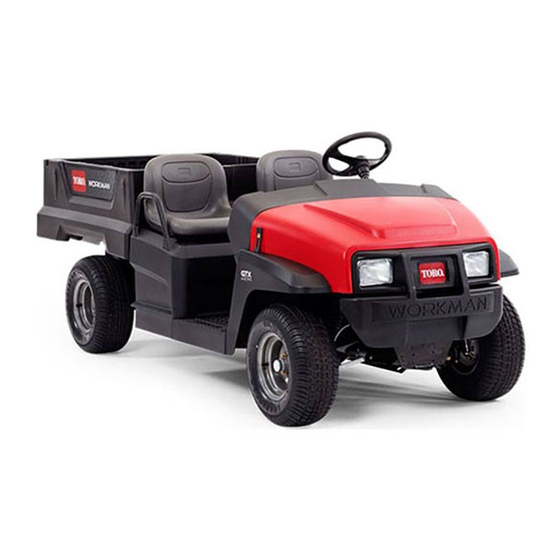
Page 13: Product Overview
Product Overview Figure 4 1. Hood latch 3. Cargo box 5. Battery charger 2. Steering wheel 4. Towing tongue 6. Cargo-box lever Figure 5 1. Passenger handhold 3. Rear cargo-box-accessory mount 2. Parking-brake lever 4. Trailer hitch... -
Page 14: Controls
Controls Figure 6 1. Light switch 7. Parking-brake lever 2. Hour meter 8. Brake pedal 3. Battery-discharge indicator 9. Accelerator pedal 4. Horn button (TC models only) 10. USB power point 5. Gear-shift selector 11. Status-indicator light 6. Key switch Accelerator Pedal Brake Pedal Use the accelerator pedal... -
Page 15: Horn Button
Parking-Brake Lever Important: Always stop the machine before changing direction. The parking-brake lever is located on the control panel (Figure Horn Button Whenever you shut off the machine, engage the parking TC Models Only brake to prevent the machine from accidental moving. If the machine is parked on a steep grade, make sure that you The horn button is located on the control panel (Figure... - Page 16 Supervisor Speed-Limit Switch Passenger Handholds The supervisor speed-limit switch, located under the seat The passenger handholds are located on the outside of each assembly, has 2 positions: P and E seat (Figure 10). ERFORMANCE CONOMY Rotate the switch clockwise to the E position to CONOMY limit the maximum machine speed to 19 km/h (12 mph).
-
Page 17: Specifications
Attachments/Accessories A selection of Toro approved attachments and accessories is available for use with the machine to enhance and expand its capabilities. Contact your Authorized Service Dealer or Distributor or go to www.Toro.com for a list of all approved... -
Page 18: Operation
Operation CAUTION If a load is concentrated near the back of the cargo Note: Determine the left and right sides of the machine box when you release the latches, the box may from the normal operating position. unexpectedly tip open, injuring you or bystanders. •... - Page 19 Raising the Cargo Box to the Service Opening the Tailgate Position 1. Ensure that the cargo box is down and latched. 1. Pull the lever on left, inside of the cargo box toward 2. Using both hands, raise the tailgate using the ridge near you and lift the cargo box up (Figure 11).
-
Page 20: Using The Rear Cargo-Box-Accessory Mount
Closing the Tailgate Using the Rear Cargo-Box-Accessory Mount If you unloaded loose material such as sand, landscaping rock, or wood chips from the cargo box of the machine, some Use the rear cargo-box-accessory mount to attach accessories of the material that you unloaded may have lodged in the to the rear of the machine. -
Page 21: Performing Pre-Starting Checks
Performing Pre-Starting Understanding and Using the Battery System Checks Service Interval: Before each use or daily Check the Understanding Deep-Cycle Batteries following items each time you begin using the machine for the day: The machine contains 8 deep-cycle, lead-acid batteries that •... - Page 22 between charges, the shorter the service life the batteries will have. • Charge frequency—fully charge the batteries whenever possible. Important: Fully discharging the batteries damages them and reduces their life. • Low water levels—if the lead plates become exposed, it may permanently damage the batteries. Perform the following to maintain the electrolyte level: After fully charging the batteries, fill the batteries with distilled or deionized water;...
-
Page 23: Stopping The Machine
Stopping the Machine Loading the Cargo Box Important: When stopping the machine on an incline, Use the following guidelines when loading the cargo box and use the service brakes to stop the machine and engage operating the machine: the parking brake to hold the machine in place. Using •... -
Page 24: Transporting The Machine
See the following table for load volume limits with various materials: Material Density Maximum Cargo Box Capacity (on level ground) Gravel, dry 1522 kg/m Full lb/ft Gravel, wet 1922 kg/m (120 3/4 Full lb/ft Sand, dry 1442 kg/m Full lb/ft Sand, wet 1922 kg/m (120... -
Page 25: Towing A Trailer
Towing a Trailer The machine is capable of pulling trailers. When hauling cargo or towing a trailer, do not overload your machine or trailer. Overloading either the machine or the trailer can cause poor performance or damage to the brakes, axle, motor, transaxle, steering, suspension, body structure, or tires. -
Page 26: Maintenance
Maintenance Note: Download a copy of the electrical schematic by visiting www.Toro.com and searching for your machine from the Manuals link. Note: Determine the left and right sides of the machine from the normal operating position. Recommended Maintenance Schedule(s) Maintenance Service... -
Page 27: Daily Maintenance Checklist
Daily Maintenance Checklist Duplicate this page for routine use. Maintenance Check Item For the week of: Monday Tuesday Wednesday Thursday Friday Saturday Sunday Check brake and parking brake operation. Check gear shift/neutral operation. Check the water level of the batteries. Check transaxle-fluid level. -
Page 28: Preparing To Maintain The Machine
Preparing to Maintain the Machine 1. Park the machine on a level surface. 2. Engage the parking brake, rotate the key switch to the position, and remove the key. Lifting the Machine Figure 23 DANGER 1. Rear lifting points The machine may be unstable when using a jack. It could slip off the jack, injuring anyone beneath it. -
Page 29: Accessing The Hood
Accessing the Hood Removing the Seat Assembly Push the seat assembly forward and lift the assembly upward Raising the hood until the retainer brackets clear the seat-base panel (Figure 25). 1. Lift up the handle of the rubber latches at each side of the hood (Figure 24). -
Page 30: Lubrication
Lubrication Greasing the Front Wheel Bearings Greasing the Machine Service Interval: Every 300 hours Service Interval: Every 100 hours/Yearly (whichever comes Grease specification: Mobilgrease XHP™-222 first)—Grease the bearings and bushings. Grease the machine more frequently Removing the Hub and Rotor when using it for heavy-duty operations. - Page 31 Greasing the Wheel Bearings 4. Remove the dust cap from the hub (Figure 31). 1. Remove the outboard bearing and bearing race from the hub (Figure 33). Figure 31 1. Cotter pin 4. Spindle nut 2. Spindle 5. Nut retainer Figure 33 3.
- Page 32 Installing the Hub and Rotor 1. Apply a light coat of the specified grease to the spindle (Figure 34). Figure 35 1. Cotter pin 3. Dust cap 2. Nut retainer Figure 34 9. Install the cotter pin and bend each legs around the 1.
-
Page 33: Electrical System Maintenance
Raising the Cargo Box to the Service Position (page 19). Note: The posts and clamps should have a bright, metallic shine. WARNING 4. Apply a light coating of Toro battery-terminal protector. CALIFORNIA Proposition 65 Warning Charging the Batteries Battery posts, terminals, and related... - Page 34 Note: Ensure that the charger-voltage setting matches Refer to the following table and Figure 36 for information on the voltage at the power outlet being used. the meanings of the varying colors of the charger-status light. Note: In high-ambient temperature environments, Charger-Status Light Table remove the seat assembly for optimal charging time;...
- Page 35 Note: The main battery cables are long when compared to battery-interconnect cables. 3. Remove the seat assembly to access the batteries; refer Removing the Seat Assembly (page 29). 4. Connect your Toro water hand pump to the water-fill port (Figure 38). G034412 Figure 39 3.
-
Page 36: Replacing The Fuses
4. Torque the nuts securing all of the battery cables until 1. Fuse block the retainer securely grips the battery. 5. Coat the battery terminals with Toro battery-terminal protector. 6. Ensure that the rubber boots on each battery cable are securely seated over the battery terminals. -
Page 37: Maintaining The Headlights
If you install a higher wattage bulb than the system is designed for, you may damage the 12 V power supply, or at a minimum, blow the fuse. Always use the specified Toro LED bulb to prevent this issue. CAUTION The bulbs become extremely hot when in operation. - Page 38 Replacing the Headlight Adjusting the Headlights 1. Disconnect the batteries; refer to Disconnecting the Use the following procedure to adjust the headlight beam Batteries (page 35). position whenever a headlight assembly is replaced or removed. 2. Open the hood; refer to Accessing the Hood (page 29).
-
Page 39: Drive System Maintenance
Adjust the riding height to the desired position by performing of the tie rods (Figure 45). the following procedure: 1. Using Toro Tool No. 6010, rotate the collar on the shock absorber to change the length of the spring (Figure 43). -
Page 40: Checking The Transaxle-Fluid Level
Changing the Transaxle Fluid Service Interval: Every 800 hours/Yearly (whichever comes first) Fluid Type: SAE 10W-30 (API service SJ or higher) Fluid Capacity: 1.4 L (1.5 US qt) 1. Align a drain pan under the drain plug (Figure 46). 2. Remove the fill plug and the seal (Figure 46). -
Page 41: Brake Maintenance
4. If the fluid level is low, perform the following: required tension, the brake pads may be worn and need A. Clean the area around the reservoir cap and to be replace. Contact your Authorized Toro Service remove the cap (Figure 48). -
Page 42: Inspecting The Brakes
Brake-Fluid Level (page 41). Replacing the Service and Parking-Brake Pads Service Interval: Every 400 hours Contact your authorized Authorized Toro Service Dealer to inspect and possibly replace the service and parking-brake pads. Figure 50 Changing the Brake Fluid 1. Bolts 2. -
Page 43: Cleaning
Cleaning Storage 1. Park the machine on a level surface, engage the parking Washing the Machine brake, shut off the machine, and remove the key. 2. Clean dirt and grime from the entire machine, including Wash the machine as needed. Use water alone or with a mild the outside of the motor housing. -
Page 44: Troubleshooting
1. None illuminated. The machine-status light flashed 1 time. 1. There is a controller-configuration fault. 1. Contact your Authorized Toro Service Dealer. The machine-status light flashed 2 times. 1. The parking brake is engaged while in 1. Disengage the parking brake. - Page 45 O position, and check for normal operation. The machine-status light flashed 12 times. 1. A controller-configuration fault 1. Contact your Authorized Toro Service occurred. Dealer. The machine-status light flashed 13 times. 1. An internal-software fault occurred. 1. Contact your Authorized Toro Service Dealer.
- Page 46 Notes:...
- Page 47 The Way Toro Uses Information Toro may use your personal information to process warranty claims, to contact you in the event of a product recall and for any other purpose which we tell you about. Toro may share your information with Toro's affiliates, dealers or other business partners in connection with any of these activities. We will not sell your personal information to any other company.
- Page 48 Countries Other than the United States or Canada Customers who have purchased Toro products exported from the United States or Canada should contact their Toro Distributor (Dealer) to obtain guarantee policies for your country, province, or state. If for any reason you are dissatisfied with your Distributor's service or have difficulty obtaining guarantee information, contact the Toro importer.