ABB AC500 Introduction Manual
Scalable plc for individual automation
Hide thumbs
Also See for AC500:
- Hardware manual (1319 pages) ,
- Installation instructions manual (262 pages) ,
- Safety instructions (24 pages)
Table of Contents
Advertisement
Advertisement
Table of Contents

Related Manuals for ABB AC500


Summary of Contents for ABB AC500
- Page 1 System Description AC500 Scalable PLC for Individual Automation Introduction...
-
Page 3: Table Of Contents
Mounting the system..........................1-42 AC500 system dimensions ........................1-48 Setting the FBP slave address ....................... 1-50 Status display and error indication on the AC500 CPU................1-52 LEDs on S500-FBP modules........................1-56 Specifications and certifications ......................1-58 Getting started with S500-FBP ....................1-59 Important user information........................ - Page 4 ____________________________________________________________________________________________________________ Introduction to AC500 AC500 / Issued: 07.2006...
-
Page 5: Survey - Gain An Overview
(7 modules max. with a maximum of 4 analog modules) Explanation The following electronic modules are the basic components of the AC500 system: • CPUs of three different performance classes • Couplers for various bus systems: Fieldbus systems PROFIBUS DP, CANopen, DeviceNet; Ethernet couplers. -
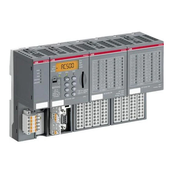
Page 6: Ac500 System Overview
AC500 is a complex state-of-the-art system providing extensive automation potential for your plant. Figure: AC500 system The following pages provide a summary of all devices available for the AC500 system. For detailed information about the individual devices please refer to the respective hardware description. - Page 7 1SAP 170 500 R0001 CM575-DN, Communication Module DeviceNet Master CM577-ETH 1SAP 170 700 R0001 CM577-ETH, Communication Module, Ethernet TCP/IP, with integrated 2-port switch CM578-CN 1SAP 170 800 R0001 CM578-CN, Communication Module, CANopen Master ____________________________________________________________________________________________________________ Introduction to AC500 AC500 / Issued: 07.2006...
- Page 8 ARCNET Slot, 1x Coupler Slot, ARCNET COAX Connector TB511-ETH 1SAP 111 100 R0170 TB511-ETH, CPU Terminal Base AC500, 1x CPU Slot, 1x Coupler Slot, Ethernet RJ45 Connector TB521- 1SAP 112 100 R0160 TB521-ARCNET, Terminal Base AC500, 1x CPU Slot, 2x...
- Page 9 TA526 1SAP 180 700 R2001 TA526, Wall mounting accessory, 10 pcs PS501-PROG 1SAP 190 100 R0001 PS501-PROG, Control Builder AC500, Programming Software German / English / French (CD-ROM incl. Online Help and PDF Docs) ____________________________________________________________________________________________________________ Introduction to AC500 AC500 / Issued: 07.2006...
-
Page 10: Bus Systems Overview
-> DEVICENET Ethernet www.ethermanage.com The Ethernet Library -> see ‘Function Block Libraries AC500’ Modbus www.modbus.org PROFIBUS www.profibus.com -> Web Based Training The PROFIBUS DP Library -> see ‘Function Block Libraries AC500’ ____________________________________________________________________________________________________________ Introduction to AC500 AC500 / Issued: 07.2006... - Page 11 ARCNET is an open, multi-purpose field bus solution with real-time capability. It can be used for multi- master networking and for programming the AC500 and AC31 controller series, but also for connecting additional ARCNET subscribers, e.g. PCs via an appropriate interface card (see catalog).
- Page 12 CAN (Controller Area Network). The difference lies in the transmission protocols. DeviceNet and CANopen can be used correspondingly for the AC500 and AC31 controller series and for field-bus-neutral FBP devices (decentralized I/Os and intelligent switching devices), via the CANopen-FBP plug connector.
- Page 13 CS31 (Communication Serial Field Bus, developed by ABB in 1989) for continuity and migration CS31 is a proprietary master/slave field bus. It is characterized by simple handling, easy configuration, and inexpensive installation. The COM1 interface of the AC500 can be configured as a CS31 field bus master. Communication Is handled using polling, i.e.
- Page 14 Ethernet defines the Layers 1 (Physical Link) and 2 (Data Link) of the OSI model. The AC500 supports transmission and reception of data using TCP/IP and/or UDP/IP. Further application layers can be implemented by subsequent loading. Simultaneous operation of TCP/IP, UDP/IP and application layer is also assured.
- Page 15 Numerous automation systems have Modbus® RTU interfaces as standard or optional features, and are thus easily able to communicate with the AC500 via its integrated COM1 and COM2 interfaces (RS232 or RS485). The Modbus® is used not only in industrial applications, but also in building installations, in energy optimization systems, for long-distance data transmission and for linking up operator panels.
- Page 16 PROFIBUS DP is an open, high-speed and widely-used field bus. It provides multi-master and master- slave communication in the field area. This field bus can accordingly be used for AC500 and AC31 control system series and for field-bus-neutral FBP devices (decentralized I/Os and intelligent switching devices) via the PROFIBUS-FBP connector.
-
Page 17: Documentation Overview
Documentation overview The documentation consists of six parts: • CoDeSys programming system - Describes the functionality of the programming software • Target system - Documentation of the AC500 system • CoDeSys libraries • CoDeSys visualization • CoDeSys HMI • CoDeSys license management... - Page 18 Introduction - Overview: Here you can gain an overview of the AC500 system. This section provides further useful information. - First steps when working with AC500 and S500-FBP; examples - For AC1131 experts Your tasks - Documentation from the user's...
- Page 19 Section Comment Block libraries - System libraries - Modbus library - Series 90 AC500 library - ASCII communication library - CS31 library - Ethernet library - PROFIBUS DP library - CANopen library - DeviceNet library - DC541 library System technology...
- Page 20 CoDeSys license management (not available) Section Comment Overview License management using the tool Creating a module which is subject to licensing Using the command 'File -> Save as -> Edit License Information dialog' ____________________________________________________________________________________________________________ Introduction to AC500 1-18 AC500 / Issued: 07.2006...
-
Page 21: Short Description Of The Hardware
Two serial interfaces for programming, ASCII, Modbus or CS31 field bus (master) Expandable by up to seven local I/O modules Figure: AC500 system, module arrangement beginning from the left: communication module, CPU, I/O module CPUs Available in three performance classes: •... -
Page 22: Short Description Of The Software
Short description of the software Programming in conformity with IEC 61131-3 AC500 Control Builder provides the following functionalities: ■ Five standardized programming languages: Function Block Diagram (FBD), Instruction List (IL), Ladder Diagram (LD), Structured Text (ST), Sequential Function Chart (SFC) ■... - Page 23 Visual Source Safe, can be used in order to ensure data consistency of the program code for several different users and projects. • Comprehensive libraries. • Windows 32-bit standard. • Operating systems Windows 2000 and XP. ____________________________________________________________________________________________________________ Introduction to AC500 1-21 AC500 / Issued: 07.2006...
-
Page 24: Operating And Displaying
Operating and displaying The AC500 offers as well an extensive range of products for communication between operator and machine. There are many different displays to choose from, which satisfy application-specific demands regarding required operator actions and information density. Users can communicate with the AC500s CPUs via the various operator panels, read and write access on device data is possible. - Page 25 150 mA 150 mA 450 mA 450 mA consumption Ambient 0 - 50 °C 0 - 50 °C 0 - 50 °C 0 - 50 °C 0 - 50 °C temperature ____________________________________________________________________________________________________________ Introduction to AC500 1-23 AC500 / Issued: 07.2006...
- Page 26 104 x 69 x 38 142 x 100 x 29 147 x 163,5 x 211 x 198 x 69 214 x 232 x 87 W x H x D (mm) Weight (kg) ____________________________________________________________________________________________________________ Introduction to AC500 1-24 AC500 / Issued: 07.2006...
- Page 27 276 x 198 x 89 138 x 100 x 30 200 x 150 x 69 200 x 150 x 69 290 x 250 x W x H x D (mm) Weight (kg) ____________________________________________________________________________________________________________ Introduction to AC500 1-25 AC500 / Issued: 07.2006...
-
Page 28: Services
Services Service - Control Engineering ABB operates a Technical Support Center to assist with even the most difficult of problems. • Consultation by phone (Helpline) • Failure analysis and removal at the machine/installation In order to provide the customer with qualified assistance, customers are requested to provide the following: •... -
Page 29: Seminars/Workshops
If desired, we also offer seminars at the customer's facility. Please find detailed information in our seminar brochure. You can order this brochure from the address given above or from every ABB STOTZ-KONTAKT GmbH office or you can download it from our Internet website (PDF file, see the following link). -
Page 30: Addresses
D-69006 Heidelberg Telephone: ++49 62 21 / 701-0 Telefax: ++49 62 21 / 701-729 http://www.abb.de/stotz-kontakt ABB Entrelec - Control Division 184, rue Léon Blum F-69100 Villeurbanne / France Telephone: ++33 (0) 4 72 35 35 Telefax: ++33 (0) 4 72 35 12 http://www.abb.com/lowvoltage... -
Page 31: Regulations Concerning The Appropriate And Safe Setup Of Systems And Installations
Qualified personnel Both the control system AC500 and other components in the vicinity are operated with dangerous contact voltages. Touching parts, which are under such voltages, can cause grave damage to health. - Page 32 In the description for the devices (operating manual or AC500 system description), reference is made at several points to earthing, electrical isolation and EMC measures. One of the EMC measures consists of discharging interference voltages into the earthing via Y-type capacitors.
- Page 33 In order to avoid electrostatic charging, the devices must only be stored when packed in suitable packaging material. Minimum clearances: Refer to target system - AC500/S500-FBP -> Introduction -> Getting Started -> Getting Started with AC500 -> Assembling the system...
-
Page 34: Getting Started With Ac500
In no event will ABB be responsible or liable for indirect or consequential damages resulting from the use or application of this equipment. -
Page 35: Before Starting
When not in use, store the equipment in appropriate static-safe packaging. Make sure that you have all the components you need To use the AC500 PLC (in our example CPU PM581-ETH) you should use at least the following parts: Part Number Designation... - Page 36 Consider the following when planning your AC500 system: • The AC500 PLC consists of a CPU Terminal Base TB5xx (from 1 to 4 coupler slots) and a pluggable CPU. Three different CPU classes are offered: from PM571 with 64kB memory up to PM591 with 4MB memory;...
- Page 37 AC500 master couplers. Program the hardware configuration. (*) Refer to the AC500 hardware description for proper wiring and addressing information. (**) Refer to the Installation Instructions for the particular FBP devices. Follow appropriate fieldbus practices outline by the conventions and standards of each protocol used in the system.
-
Page 38: Assembling The System
Using S500 I/O Modules The S500 I/O modules could be used either directly connected to an AC500 CPU (central expansion) or together with an FBP Interface Module DC505-FBP + an FBP (PROFIBUS DP, DeviceNet, etc.) as decentralized expansion. - Page 39 DC505 DC532 DC532 Figure: S500 I/O modules connected to an FBP Interface Module DC505-FBP with an FBP (decentralized expansion) ____________________________________________________________________________________________________________ Introduction to AC500 1-37 AC500 / Issued: 07.2006...
- Page 40 Mounting plate, earthed Figure: AC500/S500 module mounting into cabinets Maintain spacing from enclosure walls, wireways, adjacent equipment, etc. Allow minimum 20 mm (1 in.) of space on all sides, as shown. This provides ventilation and electrical isolation. ____________________________________________________________________________________________________________ Introduction to AC500 1-38 AC500 / Issued: 07.2006...
-
Page 41: Insertion / Replacement Of The Lithium Battery
(about 2 weeks before). After the error message appears, the battery should be replaced as soon as possible. The TA521 Lithium Battery is the only one, which can be used with AC500 CPUs. ATTENTION The following procedures describe the insertion / replacement of the Lithium battery. - Page 42 They must be stored in a dry place. Exhausted batteries must be recycled to respect the environment. Please refer to chapter "Hardware/Accessories/TA521" for the technical data sheet of the Lithium battery TA521. ____________________________________________________________________________________________________________ Introduction to AC500 1-40 AC500 / Issued: 07.2006...
-
Page 43: Insertion Of The Sd Memory Card
Insertion of the SD memory card AC500 CPUs are supplied without an SD Memory Card. It therefore must be ordered separately. The SD Memory Card is used to back-up user data and store user programs or project source codes as well as to update the internal CPU firmware. -
Page 44: Mounting The System
Step 2: Snap the AC500 Terminal Base (TB5xx) Figure: Mounting of the AC500 Terminal Base (TB5xx) The AC500 Terminal Base will be placed on top of the DIN Rail and then snapped on the bottom. Follow the reverse order to disassembly. - Page 45 When attaching the CPU Terminal Base and I/O modules, make sure the bus ATTENTION connectors are securely locked together to ensure proper electrical connection. Figure: Maximum configuration (1 CPU Terminal Base plus 7 I/O Terminal Units) ____________________________________________________________________________________________________________ Introduction to AC500 1-43 AC500 / Issued: 07.2006...
- Page 46 Terminal Units The CPU or I/O module will be plugged on the dedicated Terminal Base / Terminal Unit. And will be locked in place. The disassembly is done in reverse order. ____________________________________________________________________________________________________________ Introduction to AC500 1-44 AC500 / Issued: 07.2006...
- Page 47 Terminal Base and then rotate the coupler until it will be plugged on the dedicated Terminal Base slot, push to be sure that the connection is well done. It will be locked in place. The disassembly is done in reverse order. ____________________________________________________________________________________________________________ Introduction to AC500 1-45 AC500 / Issued: 07.2006...
- Page 48 Figure: Communication coupler module disassembly Disassembly: Press Top and Bottom, then rotate the coupler module and pull it out. ____________________________________________________________________________________________________________ Introduction to AC500 1-46 AC500 / Issued: 07.2006...
- Page 49 • the screws have a conductive surface (e.g. steel zinc-plated or brass nickel-plated) • the mounting plate is earthed • the screws have a good electrical contact to the mounting plate ____________________________________________________________________________________________________________ Introduction to AC500 1-47 AC500 / Issued: 07.2006...
-
Page 50: Ac500 System Dimensions
This product is designed to be mounted to a well-grounded mounting surface such as a metal panel. Additional grounding connections from the AC500 mounting tabs or DIN rail (if used), are not required unless the mounting surface cannot be grounded. Refer to appropriate Chapter of the S500-FBP User's Manual, for additional information. - Page 51 DIN rail 7.5 mm Dimensions: 135 mm (1.10) (5.31) inches View on the left side View on the right side Note: All dimensions are in mm (in.). Hole spacing tolerance: ±0.4 mm (0.016 in.) ____________________________________________________________________________________________________________ Introduction to AC500 1-49 AC500 / Issued: 07.2006...
- Page 52 Setting of the Slave Address of the FBP plug onto the AC500 CPU (if needed, but not recommended) Normally the FBP slave address is set using the AC500 Control Builder. Neverthless it is possible to set this address using the CPU.
- Page 53 The modified address will only be valid after a Power OFF / Power ON! ATTENTION A AC500 CPU equipped with a FieldBusPlug is always a slave device on the bus. To act as a master, a AC500 CPU should be equipped with master couplers (e.g CM572-DP for PROFIBUS DP).
-
Page 54: Status Display And Error Indication On The Ac500 Cpu
Status display and error indication on the AC500 CPU All AC500 CPUs have LEDs and a LC Display for indicating operating statuses and errors. The following drawing shows the front face of a AC500 CPU. The CPU statuses are displayed on the CPU front... - Page 55 The meanings of the LEDs and the LCD display are listed in the following table: AC500 CPU module LEDs Status Color LED = ON LED = OFF LED flashes 24 V DC green voltage is present voltage is power supply...
- Page 56 24 V DC 10 W Figure: Error display on the CPU The AC500 CPU can display various errors according to the error classes. The following error classes are possible. The reaction of the CPU is different for each type of error.
- Page 57 ESC returns to the normal state without ack- I/O-Bus COM2 nowledging the error! Figure: Example of an error display for an exhausted battery Please refer to the Error Code list for further information. See the AC500 user manual. ____________________________________________________________________________________________________________ Introduction to AC500 1-55 AC500 / Issued: 07.2006...
-
Page 58: Leds On S500-Fbp Modules
*) All of the LEDs CH-ERR1 to CH-ERR4 (as far as they exist) light up together For the meaning of the different LEDs and their behaviour when the system is running, please refer to the S500 System Data of the S500 User’s manual for further information. ____________________________________________________________________________________________________________ Introduction to AC500 1-56 AC500 / Issued: 07.2006... - Page 59 FBP LEDs – PROFIBUS DP ____________________________________________________________________________________________________________ Introduction to AC500 1-57 AC500 / Issued: 07.2006...
- Page 60 AC500 Modules Specifications Please refer to the AC500 User’s Manual chapter System Data. AC500 Modules Certifications Please refer to the AC500 User’s Manual chapter System Data. ____________________________________________________________________________________________________________ Introduction to AC500 1-58 AC500 / Issued: 07.2006...
-
Page 61: Getting Started With S500-Fbp
In no event will ABB be responsible or liable for indirect or consequential damages resulting from the use or application of this equipment. - Page 62 24 V DC analog sensor or AX521(4AI/4AO U/I/PT100) or AX522 (8AI/8AO actuator to the device U/I/PT100) + corresponding Terminal Unit TU515/516 • TA523 (Pluggable marking holder) + TA525 Label the I/O Channels Markers for marking holder. ____________________________________________________________________________________________________________ Introduction to AC500 1-60 AC500 / Issued: 07.2006...
- Page 63 Set the correct address onto the FBP Interface Module (rotary switches) Install the appropriate EDS/GSD files into the Fieldbus configurator (for use with AC31 or AC500 Control Builder) or use a dedicated Fieldbus Configurator tool using GSD/EDS configuration files of your Master device...
- Page 64 Be sure that power is removed or area is non-hazardous before proceeding. Using S500 I/O Modules The S500 I/O modules could be used either directly connected to an AC500 CPU (central expansion) or together with an FBP Interface Module DC505-FBP + an FBP (PROFIBUS DP, DeviceNet, etc.) as decentralized expansion.
- Page 65 DC505 DC532 DC532 Figure: S500 I/O modules connected to an FBP Interface Module DC505-FBP with an FBP (decentralized expansion) ____________________________________________________________________________________________________________ Introduction to AC500 1-63 AC500 / Issued: 07.2006...
- Page 66 Mounting plate, earthed Figure: AC500/S500 module mounting into cabinets Maintain spacing from enclosure walls, wireways, adjacent equipment, etc. Allow minimum 20 mm (1 in.) of space on all sides, as shown. This provides ventilation and electrical isolation. ____________________________________________________________________________________________________________ Introduction to AC500 1-64 AC500 / Issued: 07.2006...
- Page 67 Important: Horizontal mounting is highly recommended. Vertical mounting is possible, however, derating consideration should be made to avoid problems with poor air circulation and the potential for excessive temperatures (see also the AC500 system data, operating and ambient conditions, for reduction of ambient temperature).
- Page 68 Up to 7 I/O Terminal Units could be combined with a FBP Terminal Unit. When attaching the FBP, FBP Interface and I/O modules, make sure the bus ATTENTION connectors are securely locked together to ensure proper electrical connection. ____________________________________________________________________________________________________________ Introduction to AC500 1-66 AC500 / Issued: 07.2006...
- Page 69 Figure: Maximum configuration (1 FBP Terminal Unit plus 7 I/O Terminal Units) Disassembly of a Terminal Unit Figure: I/O Terminal Unit disassembly (TU515, TU516, TU531 or TU532) A screwdriver is inserted in the indicated place to separate the Terminal Units. ____________________________________________________________________________________________________________ Introduction to AC500 1-67 AC500 / Issued: 07.2006...
- Page 70 The module will be plugged on the Terminal Unit. And will be locked in place. The disassembly is done in reverse order. Figure: Module disassembly For disassembly, press top and bottom, then pull out the module. ____________________________________________________________________________________________________________ Introduction to AC500 1-68 AC500 / Issued: 07.2006...
- Page 71 TIP: If mounting more modules, mount only the last one of this group and put the others aside. This reduces remounting time during drilling and tapping of the next group. 7. Repeat steps 1 to 6 for any remaining modules. ____________________________________________________________________________________________________________ Introduction to AC500 1-69 AC500 / Issued: 07.2006...
-
Page 72: S500 System Dimensions
S500 system dimensions 57.7 (2.27) DC505 67.5 (2.66) 67.5 (2.66) Dimensions: 135 mm TU505/506 TU515/516/531/532 (5.31) inches Figure: Dimensions of the Terminal Unit (front view) ____________________________________________________________________________________________________________ Introduction to AC500 1-70 AC500 / Issued: 07.2006... - Page 73 View on the left side View on the right side Figure: Dimensions of the Terminal Unit with module (lateral view) Note: All dimensions are in mm (in.). Hole spacing tolerance: ±0.4 mm (0.016 in.) ____________________________________________________________________________________________________________ Introduction to AC500 1-71 AC500 / Issued: 07.2006...
-
Page 74: Setting The Fbp Slave Address
The FieldBusPlug module has to be connected to the master device and the power supply has to be provided. Please use the dedicated accessories to the FBP used for the desired Fieldbus. Refer to the FBP documentation for the installation instructions. ____________________________________________________________________________________________________________ Introduction to AC500 1-72 AC500 / Issued: 07.2006... - Page 75 *) All of the LEDs CH-ERR1 to CH-ERR4 (as far as they exist) light up together For the meaning of the different LEDs and their behaviour when the system is running, please refer to the S500 System Data of the S500 User’s manual for further information. ____________________________________________________________________________________________________________ Introduction to AC500 1-73 AC500 / Issued: 07.2006...
- Page 76 FBP LEDs – PROFIBUS DP ____________________________________________________________________________________________________________ Introduction to AC500 1-74 AC500 / Issued: 07.2006...
- Page 77 S500-FBP Modules Specifications Please refer to the S500 User’s Manual chapter System Data. S500-FBP Modules Certifications Please refer to the S500 User’s Manual chapter System Data. ____________________________________________________________________________________________________________ Introduction to AC500 1-75 AC500 / Issued: 07.2006...
-
Page 78: Examples
• One digital I/O module DC532 (DX522 or DX531 as an alternative) and one I/O terminal unit (e.g. TU516). • One 24 VDC power supply. • A PC with the programming software PS501 installed. • One cable (TK501) to connect the PC to the basic unit. ____________________________________________________________________________________________________________ Introduction to AC500 1-76 AC500 / Issued: 07.2006... - Page 79 ATTENTION (configure) the device configuration in the programming software. Otherwise the system will bring up corresponding error messages! In case of errors, please refer to the chapter "System Technology / Diagnosis System in AC500" for required information. ____________________________________________________________________________________________________________ Introduction to AC500 1-77 AC500 / Issued: 07.2006...
- Page 80 Creating a new project Select "File/New". Select the desired CPU in the appearing window. In our example, select PM581 . In the appearing window confirm with OK . ____________________________________________________________________________________________________________ Introduction to AC500 1-78 AC500 / Issued: 07.2006...
- Page 81 You have now opened a new project. Note: All necessary libraries are loaded automatically. Saving the project to the PC First of all save the project by selecting the menu item "File/Save as". ____________________________________________________________________________________________________________ Introduction to AC500 1-79 AC500 / Issued: 07.2006...
- Page 82 Specifying the hardware configuration The software has to be informed about the hardware configuration, i.e. the hardware configuration has to be specified in the software (e.g. the I/O devices). Click on ____________________________________________________________________________________________________________ Introduction to AC500 1-80 AC500 / Issued: 07.2006...
- Page 83 Double click the object "PLC Configuration". If the AC500 folder in the PLC configuration tree is closed, click on the symbol. Click on "I/O-Bus[FIX]" and then press the right mouse button. ____________________________________________________________________________________________________________ Introduction to AC500 1-81 AC500 / Issued: 07.2006...
- Page 84 8 ms (default) to 1 ms. This way you can also configure the inputs and outputs of the S500-FBP interface module DC505-FBP in order to use them as decentralized inputs and outputs. ____________________________________________________________________________________________________________ Introduction to AC500 1-82 AC500 / Issued: 07.2006...
- Page 85 These configurable I/Os are displayed in the I/O mapping either as inputs or as outputs according to how the channel will be used by the user! ____________________________________________________________________________________________________________ Introduction to AC500 1-83 AC500 / Issued: 07.2006...
- Page 86 ____________________________________________________________________________________________________________ Introduction to AC500 1-84 AC500 / Issued: 07.2006...
- Page 87 Single digital configurable I/Os as output as a bit for the configurable output 24 output 24 to the output 31 single digital configurable output 31 %QX1.7 For more details concerning the I/O mapping, please refer to the AC500 User's manual. ____________________________________________________________________________________________________________ Introduction to AC500 1-85 AC500 / Issued: 07.2006...
- Page 88 Using the same procedure, we then have to label the digital output with a symbolic name. Click on the symbol in front of the entry "Digital In/Outputs - outputs 16-31 [FIX]". ____________________________________________________________________________________________________________ Introduction to AC500 1-86 AC500 / Issued: 07.2006...
- Page 89 Now we have to enter the symbolic names previously assigned to the input and the output. Click on the left-hand question marks (???) and press <F2>. The Help Manager appears. Select "System Variables". ____________________________________________________________________________________________________________ Introduction to AC500 1-87 AC500 / Issued: 07.2006...
- Page 90 PC assigned by the USB RS-232 converter. Switch to the tab. Double click the object "PLC Configuration". In the configuration tree, click on the symbol in front of the "Interfaces[FIX]" element. ____________________________________________________________________________________________________________ Introduction to AC500 1-88 AC500 / Issued: 07.2006...
- Page 91 Click on the entry "COM2 - Online access[SLOT]" in order to display the default values of the PLC's COM2 interface. Then we have to define the PC interface settings. Select the menu item "Online/Communication Parameters". ____________________________________________________________________________________________________________ Introduction to AC500 1-89 AC500 / Issued: 07.2006...
- Page 92 Now the "Communication Parameters" dialog displays the PC interface. Press the "New" button. Enter any name for the new channel, e.g. COM1_PC, and select "Serial [RS232]" for the "Device" (driver). Confirm your settings with "OK". ____________________________________________________________________________________________________________ Introduction to AC500 1-90 AC500 / Issued: 07.2006...
- Page 93 If the project on the PLC differs from the project on the PC, the following message is displayed: Select "Yes". Then the program is downloaded from the PC to the PLC. When starting the download process, the PLC changes to the STOP mode. ____________________________________________________________________________________________________________ Introduction to AC500 1-91 AC500 / Issued: 07.2006...
- Page 94 Now we want to run the program. Select the menu item "Online/Run": In order to test the program we are going to force input I0dig to TRUE: Double click to the input "I0dig": ____________________________________________________________________________________________________________ Introduction to AC500 1-92 AC500 / Issued: 07.2006...
- Page 95 This way, the input is assigned to the output (i.e. set to TRUE) in each program cycle. The CoDeSys software displays the TRUE state in blue color (the FALSE state is displayed in black). This way, the input I0dig is assigned to output O0dig. ____________________________________________________________________________________________________________ Introduction to AC500 1-93 AC500 / Issued: 07.2006...
- Page 96 Note: The status of the I/Os can also be displayed in the PLC configuration. Click on Double click on “PLC configuration”. ____________________________________________________________________________________________________________ Introduction to AC500 1-94 AC500 / Issued: 07.2006...
- Page 97 Using "Online/Logout", the connection to the PLC is disconnected and the Force function is canceled. To exit the CoDeSys software, select the menu item "File/Exit". ____________________________________________________________________________________________________________ Introduction to AC500 1-95 AC500 / Issued: 07.2006...
-
Page 98: Examples For Decentralized Systems Connected By Network
USB RS-232 converter. The following example will guide you through the installation and the configuration of a small PROFIBUS DP fieldbus using an AC500 PLC as PROFIBUS DP master and a S500-FBP remote I/O station with a modular FBP. - Page 99 Connect the programming cable TK501 from the PC to the AC500 PLC • Review all of the hardware instructions for your specific system to be sure you have completed all of the required preliminary steps prior to beginning the system configuration with the AC500 Control Builder programming software. •...
- Page 100 Starting the programming software Start the AC500 Control Builder programming software. Select "File/New" to create a new project. Select the desired CPU in the appearing window. In our example, select PM581 . In the appearing window confirm with "OK". ____________________________________________________________________________________________________________...
- Page 101 First, save the project under a specific name. Select the menu item "File/Save as". Select the desired directory and enter the project name (in our example: "Test3"). Complete your input with "Save". ____________________________________________________________________________________________________________ Introduction to AC500 1-99 AC500 / Issued: 07.2006...
- Page 102 Specifying the hardware configuration The software has to be informed about the hardware configuration, i.e. the hardware configuration has to be specified in the software. Click on ____________________________________________________________________________________________________________ Introduction to AC500 1-100 AC500 / Issued: 07.2006...
- Page 103 Double click the object "PLC Configuration". If the AC500 folder in the PLC configuration tree is closed, click on the symbol. First the I/O devices connected directly to the I/O bus of the CPU will be entered: Click on "I/O-Bus[FIX]"...
- Page 104 Select "Append Subelement" -> "DC532". Repeat this procedure to append the analog module AX522. ____________________________________________________________________________________________________________ Introduction to AC500 1-102 AC500 / Issued: 07.2006...
- Page 105 The coupler is appended to the tree. As the CPU also comprises an integrated Ethernet coupler we are going to replace ‘Couplers – Internal none’ by an Ethernet coupler. ____________________________________________________________________________________________________________ Introduction to AC500 1-103 AC500 / Issued: 07.2006...
- Page 106 "Master". With the left mouse button, click on CM572-DPM. Keep the left mouse button pressed and drag the object into the left window to append it to the green line (this line represents the connection to the CPU). Release the left mouse button. ____________________________________________________________________________________________________________ Introduction to AC500 1-104 AC500 / Issued: 07.2006...
- Page 107 Recommendation: You can choose the symbolic coupler name according to your plant (mark coupler with left mouse button; the coupler is displayed with a blue rectangle; press right mouse button -> symbolic name. Example for symbolic name: DPM1_AC500). ____________________________________________________________________________________________________________ Introduction to AC500 1-105 AC500 / Issued: 07.2006...
- Page 108 "Slave" folder in the "Fieldbus" tab. Drag the PROFIBUS DP FieldBusPlug PDP22-FBP (DPV1 modular) into the left-hand window to append it to the purple line (this line represents the PROFIBUS DP fieldbus). ____________________________________________________________________________________________________________ Introduction to AC500 1-106 AC500 / Issued: 07.2006...
- Page 109 The slave has to be correctly software configured and mapped to precisely match the true hardware configuration. Double click on the PDP22-FBP symbol to open a new configuration window. In this window the hardware configuration is described and some parameter settings can be defined. ____________________________________________________________________________________________________________ Introduction to AC500 1-107 AC500 / Issued: 07.2006...
- Page 110 The order of the modules in the list of configured modules must match the actual ATTENTION order of hardware modules. Otherwise, the decentralized station and the network cannot work properly! ____________________________________________________________________________________________________________ Introduction to AC500 1-108 AC500 / Issued: 07.2006...
- Page 111 Repeat this procedure to append the modules DC532 and AX522. Then, the list of configured modules looks as follows: Proceed as follows to configure the module parameters. Click on "Configuration -> Parameters". Select the corresponding module from the list. Click on the corresponding module. ____________________________________________________________________________________________________________ Introduction to AC500 1-109 AC500 / Issued: 07.2006...
- Page 112 The configuration of the fieldbus modules is finished. Now the names of the communication variables used for data exchange between coupler and CPU program have to be specified. Proceed as follows to specify the variables (these variables are automatically forwarded to the AC500 Control Builder software in order to have them available there):...
- Page 113 Name of variable field of the corresponding signal. Enter the desired variable name and press the <Enter> key to complete your entry. These names are used in the AC500 Control Builder software. In our example, we use the following system for the variable name: by tePROFIBUS Dps laveAddress 2_S500 (system) _DC505 (device) _In put 8_ to 15 (by - byte;...
- Page 114 Assign a name to each variable. For the 8 DC (as outputs) of the DC505-FBP module: For the 16 DI + 16 DC (as inputs) of the DC532 module: ____________________________________________________________________________________________________________ Introduction to AC500 1-112 AC500 / Issued: 07.2006...
- Page 115 For the 16 DC (as outputs) of the DC532 module: For the 8 analog inputs of the AX522 module: ____________________________________________________________________________________________________________ Introduction to AC500 1-113 AC500 / Issued: 07.2006...
- Page 116 Now the configuration has to be loaded from SYCON.net to the coupler CM572-DP. Proceed as follows: In the netDevice window, click on the coupler to highlight it with a blue frame: ____________________________________________________________________________________________________________ Introduction to AC500 1-114 AC500 / Issued: 07.2006...
- Page 117 Double click on the coupler icon and select "Settings -> Driver -> 3S Gateway Driver". Select "Gateway Configuration". In the Communication Parameters window, you can set the parameters for the communication between the PC and the PLC (port: serial interface of the PC). ____________________________________________________________________________________________________________ Introduction to AC500 1-115 AC500 / Issued: 07.2006...
- Page 118 Confirm the settings with "OK". Select "Settings -> Driver -> Device Assignment" and click on "Scan". The configuration tool SYCON.net searches for PROFIBUS couplers connected to the stated interface. Select the device "CM572-DP" and confirm with "OK". Then press the right mouse button and select "Connect". ____________________________________________________________________________________________________________ Introduction to AC500 1-116 AC500 / Issued: 07.2006...
- Page 119 The coupler entry CM572-DPM is now highlighted in green, indicating that the connection is established: Press the right mouse button and select "Download". ATTENTION: To do this the CPU must be in ‘Stop’ state. A safety inquiry is displayed. Confirm with "Yes". ____________________________________________________________________________________________________________ Introduction to AC500 1-117 AC500 / Issued: 07.2006...
- Page 120 After the download is completed, SYCON.net has to be disconnected. Press the right mouse button and select "Disconnect". In SYCON.net, the configuration has to be saved to a file. The system adopts the project name (in our example: "Test3"). Select "File/Save". Exit SYCON. Select "File/Exit". ____________________________________________________________________________________________________________ Introduction to AC500 1-118 AC500 / Issued: 07.2006...
- Page 121 Windows task bar on the bottom of the screen. The AC500 Control Builder software is opened again and the fieldbus variables are automatically transferred to the Global Variables list of the programming software. Open the Global Variables in the "Resources" tab. Double click on Slot 1 <R> . The previously configured variables are displayed and available in the programming software.
- Page 122 Attention: Handling of GSD files only works that way in case of an empty project! Click on . Open the 'Tools' folder. Double click on the entry SYCON.net. Click into the window next to netDevice and select "Network/Device Catalog…" from the menu. ____________________________________________________________________________________________________________ Introduction to AC500 1-120 AC500 / Issued: 07.2006...
- Page 123 Click on . This integrates the new GSD file. Click on OK and close SYCON.net. ____________________________________________________________________________________________________________ Introduction to AC500 1-121 AC500 / Issued: 07.2006...
- Page 124 This example could be used as starting point to realize your own application. Refer to the dedicated User's manuals or Installation guides of the ATTENTION FieldBusPlug and the AC31 PLCs and programming software. ____________________________________________________________________________________________________________ Introduction to AC500 1-122 AC500 / Issued: 07.2006...
- Page 125 Connect the PC (COM1) to the AC31 CPU (COM1) using the programming cable 07 SK 90. • Connect the CPU to the DC505-FBP module via the FieldBusPlug. • Switch on voltage. • Perform the steps given in the following instructions. ____________________________________________________________________________________________________________ Introduction to AC500 1-123 AC500 / Issued: 07.2006...
- Page 126 For our example: CPU with identification number R0272 -> slot number 1 -> Ethernet; slot number 2 -> PROFIBUS DP • Since we are using the PROFIBUS coupler in our example, the resulting card number is 2. Confirm with "OK". ____________________________________________________________________________________________________________ Introduction to AC500 1-124 AC500 / Issued: 07.2006...
- Page 127 In the appearing window, select "PDP22-FBP (DPV1 modular) (Default)" in the File Name list box. Confirm with "OK". Click on the entry "PDP22-FBP (DPV1 modular). Press the right mouse button and select "Properties". ____________________________________________________________________________________________________________ Introduction to AC500 1-125 AC500 / Issued: 07.2006...
- Page 128 In addition, the configuration data can be saved together with the user program in the Flash memory of the controller. The configuration data stored in the Flash memory are automatically loaded the next time the power is switched on. ____________________________________________________________________________________________________________ Introduction to AC500 1-126 AC500 / Issued: 07.2006...
- Page 129 You can change the default address of the master and enter a comment in the 'Description' field. Click on OK and continue. ____________________________________________________________________________________________________________ Introduction to AC500 1-127 AC500 / Issued: 07.2006...
- Page 130 Then click on ADD >> . Your selection is displayed on the right-hand side of the window. In this window, you can also change the default station address and enter a description for the device. Then click on OK . ____________________________________________________________________________________________________________ Introduction to AC500 1-128 AC500 / Issued: 07.2006...
- Page 131 DC505-FBP (list of available modules ('Module' column) in the window shown above; the selected module is highlighted by a rectangle). Click on Append Module to insert it into the list of configured modules. ____________________________________________________________________________________________________________ Introduction to AC500 1-129 AC500 / Issued: 07.2006...
- Page 132 If you want to change the device parameters of the slave, select the device entry to highlight it by a rectangle. Press the right mouse button and select Parameter Data from the context menu. ____________________________________________________________________________________________________________ Introduction to AC500 1-130 AC500 / Issued: 07.2006...
- Page 133 Select dc532 1sap240100r0001 and click on OK . The corresponding module parameters are displayed and can be changed now. Example: In order to change the delay time of the inputs, double click on Input Delay . ____________________________________________________________________________________________________________ Introduction to AC500 1-131 AC500 / Issued: 07.2006...
- Page 134 A new window appears, showing all available values. Select the desired value, e.g. 1 ms, and click on OK . The new value is applied. After you have changed all the desired parameters, click on OK to exit the parameter configuration. The following configuration is displayed: ____________________________________________________________________________________________________________ Introduction to AC500 1-132 AC500 / Issued: 07.2006...
- Page 135 (click on the master to highlight it by a surrounding rectangle). Select the menu item Online -> Download . Select 3S Gateway Driver as gateway for the download to the CPU coupler and click on OK . ____________________________________________________________________________________________________________ Introduction to AC500 1-133 AC500 / Issued: 07.2006...
- Page 136 DP coupler in the CPU (this is only done when the gateway is used the first time). Click on Gateway Configuration and then select the default channel COM1_PC in the appearing window. Apply the selection by clicking on OK . ____________________________________________________________________________________________________________ Introduction to AC500 1-134 AC500 / Issued: 07.2006...
- Page 137 The address data used can be displayed using the menu item View -> Address Table . The digital inputs can be accessed via IB0 to IB5, the digital outputs via QB0 to QB2 and the analog outputs via QW3 to QW11. ____________________________________________________________________________________________________________ Introduction to AC500 1-135 AC500 / Issued: 07.2006...
- Page 138 CPU. The program looks as follows: The first byte on the DC505-FBP is read at address %IB2.0 and output at the CPU via the address %QB124 (outputs A62,00 to A62,07). ____________________________________________________________________________________________________________ Introduction to AC500 1-136 AC500 / Issued: 07.2006...
Need help?
Do you have a question about the AC500 and is the answer not in the manual?
Questions and answers