ABB AC500-S Safety User Manual
Safety programmable logic controllers system
Hide thumbs
Also See for AC500-S:
- Safety user manual (404 pages) ,
- Application note (24 pages) ,
- System manual (119 pages)
Table of Contents
Advertisement
Advertisement
Table of Contents

Related Manuals for ABB AC500-S


Summary of Contents for ABB AC500-S
- Page 1 AC500-S Safety User Manual V1.0.4 Original Instructions...
- Page 2 68526 Ladenburg, Germany Telephone: +49 62 21 701 1444 Fax: +49 62 21 701 1382 E-mail: plc.sales@de.abb.com Internet: www.abb.com/plc 3ADR025091M0205 Reproduction, use or disclosure to third parties without express authority is strictly forbidden. © Copyright 2012-2017 ABB. All rights reserved AC500-S 30.03.2017...
-
Page 3: Table Of Contents
2.6 Lifecycle............................21 2.7 Installation of safety modules......................21 2.8 Exchange of modules........................22 2.9 AC500-S restart behaviour......................22 2.10 Replacing AC500-S Safety PLC components................22 2.11 Environmentally friendly disposal....................22 2.12 Safe communication........................23 2.13 Safety function and fault reaction....................24 2.13.1 Safety CPU (SM560-S)...................... - Page 4 3.6.2 Mounting, dimensions and electrical connection..............159 3.6.3 Technical data.......................... 162 3.6.4 Ordering data........................... 164 Configuration and programming..................... 165 4.1 Overview............................. 165 4.2 Workflow............................. 167 4.3 System configuration and programming..................168 4.3.1 Installation..........................169 4.3.2 License activation........................169 AC500-S 30.03.2017...
- Page 5 6.3 Checklist for configuration and wiring..................409 6.4 Checklist for operation, maintenance and repair................. 410 6.5 Verification procedure for safe iParameter setting in AC500-S Safety I/Os........ 412 6.5.1 Verification procedure workflow....................413 6.5.2 Verification tables for iParameter settings in AC500-S Safety I/Os.......... 417 Safety application examples......................
- Page 6 7.4.1 Functional description of safety functions................437 7.4.2 Graphical overview of the safety application interface............. 438 7.4.3 Declaration of used variables....................438 7.4.4 Program example........................440 7.4.5 Additional notes........................440 Index..............................442 Appendix............................445 A System data for AC500-S-XC......................446 AC500-S 30.03.2017...
-
Page 7: Introduction
Introduction 1.1 Purpose This Safety User Manual describes AC500-S Safety PLC system. It provides detailed information on how to install, run, program and maintain the system correctly in functional safety applications up to SIL3 according to IEC 61508 ed. 2, IEC 62061 and Performance Level e according to ISO 13849. -
Page 8: Document History
Safety Function Response Time calculation. The values for input delay accuracy in Safety Function Response Time calculation were updated. Update of Appendix A with system data for AC500-S-XC. 1.0.2 Words "Original Instructions" have been added to document title 17.04.2015... - Page 9 Ch 4.6.1: Table for library “SAFETYBASE_PROFI- safe_AC500_V22_Ext.lib” was updated. Ch. 4.6.3: The chapter was updated and renamed acc. to the new library name “SAFETYBASE_PROFI- safe_AC500_V22_Ext.lib”. Ch. 6.2: Checklist item 20 was updated according to the new library name “SAFETYBASE_PROFIsafe_AC500_V22_Ext.lib”. 30.03.2017 AC500-S...
-
Page 10: Validity
Introduction Important user information 1.3 Validity The data and illustrations found in this documentation are not binding. ABB reserves the right to modify its products in line with its policy of continuous product development. 1.4 Important user information This documentation is intended for qualified personnel familiar with Functional Safety. You must read and understand the safety concepts and requirements presented in this Safety User Manual prior to operating AC500-S Safety PLC system. -
Page 11: Definitions, Expressions, Abbreviations
One-out-of-Two safety architecture, which means that it includes two channels connected in parallel, such that either channel can process the safety function. AC500-S ABB Safety PLC for applications up to SIL3 (IEC 61508 ed. 2 and IEC 62061) and PL e (ISO 13849) AC500-S-XC ABB Safety PLC for applications up to SIL3 (IEC 61508 ed. - Page 12 Original Equipment Manufacturer Passivation The passivation is the special state of Safety I/O modules which leads to the delivery of safe substitute values, which are ‘0’ values in AC500-S, to the Safety CPU. PELV Protective Extra Low Voltage Programmable Electronic System (see IEC 61508 ed. 2)
-
Page 13: Functional Safety Certification
1.6 Functional safety certification The AC500-S Safety Modules are safety-related up to SIL3 according to IEC 61508 ed. 2, IEC 62061 and Performance Level e according to ISO 13849, as certified by TÜV Süd Rail GmbH (Germany). -
Page 14: References/Related Documents
The proof test interval for the AC500-S Safety PLC is set to 20 years. PFH, PFD, MTTFd, Category and DC values from IEC 62061, IEC 61508 ed. 2 and ISO 13849 for AC500-S Safety Modules satisfy SIL3 and PL e requirements. -
Page 15: Overview Of Ac500-S Safety Plc
2.1 Overview The AC500-S is realized as 1oo2 system (both Safety CPU and Safety I/O modules) and can be used to handle safety functions with SIL3 (IEC 61508 ed. 2 and IEC 62061) and PL e (ISO 13849) requirements in high-demand systems of safety machinery applications. -
Page 16: System
Overview > System 2.1.1 System The AC500-S Safety PLC is an integrated part of AC500 platform with a real common Look & Feel engi- neering approach. Due to a tight integration in AC500 PLC platform, the generic AC500 system characteris- tics (mechanics, programming, configuration etc.) are also valid for AC500-S Safety modules. -
Page 17: Safety Components
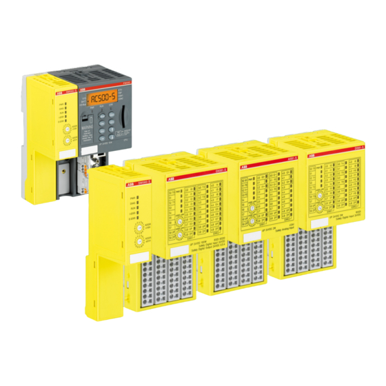
Standard I/O module (Fig. 2/5) With ABB’s standard I/O modules, the complete S500 and S500-eCo I/O module range can be con- nected to the standard PLC. A wealth of functions in AC500 configurable I/O modules allows getting the customized and low-priced solutions to optimize industrial applications. - Page 18 Overview of AC500-S Safety PLC Overview > Safety components Safety binary input module DI581-S with 16 safety input channels (up to SIL2 or PL d) or 8 safety input chan- nels (up to SIL3 or PL e) with 8 test pulse output channels.
-
Page 19: Intended Use
Spring-type terminal unit TU582-S for Safety I/O modules. 2.2 Intended use The user shall coordinate usage of ABB AC500-S safety components in his applications with the competent authorities and get their approval. ABB assumes no liability or responsibility for any consequences arising... -
Page 20: Safety Loop
For the calculation of the PFH/PFD values of an examplary safety system, a maximum of 15 % is assumed for the Safety PLC. The detailed values of PFH for AC500-S Safety modules and PFH/PFD of the Safety PLC Loop can be obtained on request. -
Page 21: Qualified Personnel
All AC500-S safety modules have a maximum life of 20 years. This means that all AC500-S safety modules shall be taken out of service or replaced by new AC500-S safety modules at least one week before the expiry of 20 years (counted from the date of delivery by ABB). -
Page 22: Exchange Of Modules
Hardware components for AC500-S (Safety CPU and Safety I/Os) are replaced in the same way as in a standard AC500 automation system. 2.11 Environmentally friendly disposal All AC500-S safety components from ABB are designed with a minimal environment pollution effect. -
Page 23: Safe Communication
PROFINET IO devices. PROFINET devices CI501, CI502, CI504 and CI506 (Release date: 2013 and newer) can be used to attach Safety I/O modules in remote configurations. Fig. 4 shows a possible system setup with PROFINET/PROFIsafe for remote Safety I/Os, sensors and actors. Fig. 4: AC500-S system setup with PROFINET / PROFIsafe 30.03.2017 AC500-S... -
Page 24: Safety Function And Fault Reaction
De-energized outputs The purpose of AC500-S safety function is to enable a machine (as a system) to achieve with a given SIL (IEC 61508 ed. 2, IEC 62061) and PL (ISO 13849) a system safe state. An exemplary Safety Function on the application level, which can be executed by AC500-S in machinery applications, is the Emergency Stop. -
Page 25: Safety Module With Safety Input Channels (Di581-S, Dx581-S And Ai581-S)
Overview of AC500-S Safety PLC Safety function test The application program developer must implement a specific fault reaction, e.g., setting safety output chan- nels to de-energized (‘0’ state), when required. 2.13.2 Safety module with safety input channels (DI581-S, DX581-S and AI581-S) The safety function of safety modules (DI581-S, DX581-S and AI581-S) with digital and analog input chan- nels is to correctly read external analog and/or digital signals. -
Page 26: Troubleshooting
Error messages in the diagnosis buffer of PM5xx Non-safety CPU include “Remedy” section, which shall help you to fix potential problems with AC500-S configuration. If some of problems persist or no error mes- sages are available in the diagnosis buffer, contact ABB technical support for further details. - Page 27 Overview of AC500-S Safety PLC Troubleshooting Behaviour Potential Cause Remedy DX581-S module is powered Wiring error on DX581-S Check the wiring of DX581-S on, but no power supply is con- module when +24 V DC is con- and disconnect +24 V DC from...
- Page 28 Overview of AC500-S Safety PLC Troubleshooting Behaviour Potential Cause Remedy Set “Enable debug” param- CoDeSys Safety does not sup- After powering off/on of SM560- eter to “OFF” on SM560-S port the described use case. S Safety CPU, the correct boot...
- Page 29 Overview of AC500-S Safety PLC Troubleshooting Behaviour Potential Cause Remedy One executes “Login” com- CoDeSys Safety instance After resetting SM560-S Safety mand in CoDeSys Safety attempts to login to SM560-S CPU password, close CoDeSys and uses “setpwd” PLC Safety CPU with an old pass-...
- Page 30 Overview of AC500-S Safety PLC Troubleshooting Behaviour Potential Cause Remedy After power-on of SM560-S SM560-S power dip function is Do power-off and power-on of Safety CPU, it may happen that triggered if the pause between SM560-S Safety CPU with a...
- Page 31 Overview of AC500-S Safety PLC Troubleshooting Behaviour Potential Cause Remedy “Enable debug” parameter = CoDeSys Safety projects on Download your CoDeSys “ON” was set for SM560-S your PC and in SM560-S Safety Safety project from your PC to Safety CPU and correctly CPU are not the same.
-
Page 32: Ac500-S Safety Modules
SM560-S Safety CPU for AC500 PLCs is available from version V2.2.1 (or newer) of the PS501 Control Builder Plus software / version 1.0 (or newer) of the ABB Automation Builder software and can be used with Non-safety CPUs (PM573, PM583, PM592 or others with the firmware version from V2.2.1 and with suitable TB5xx units). - Page 33 AC500-S Safety Modules SM560-S Safety CPU > Functionality The firmware version of the used Non-safety CPU must be V2.2.1 or above. Programming of the Safety CPU is done using CoDeSys Safety in exactly the same way as programming of AC500 CPU, but in accordance with the guidelines [1].
- Page 34 POUs SF_DPRAM_PM5XX_S_SEND, SF_DPRAM_PM5XX_S_REC, DPRAM_SM5XX_SEND and DPRAM_SM5XX_REC ( Ä Chapter 4.6 “AC500-S Libraries” on page 224 for further details) on both CPUs. DANGER! It is of no concern to transfer data values from Safety CPU to Non-safety CPU (e.g., for diagnosis and later visualization on the operator panels), but it is not recommended to transfer data values from Non-safety CPU to Safety CPU.
- Page 35 I-ERR LED = ON. To avoid continuous automatic restart of SM560-S after power supply is back within an allowed voltage range, one can set the maximum allowed number of SM560-S restarts using POU Ä Chapter 4.6 “AC500-S Libraries” on page 224 for further details). As soon SF_MAX_POWER_DIP_SET ( as the maximum allowed number of SM560-S restarts is exceeded, the Safety CPU does not restart auto- matically and remains in the SAFE STOP state until the user explicitly executes powering off/on procedure.
- Page 36 AC500-S Safety Modules SM560-S Safety CPU > Functionality Switch address value 0xFD during the start of SM560-S allows deleting user data from the Flash memory of SM560-S. The user data are finally deleted after SM560-S powering off/on is executed. This can be needed if user data are corrupt and could lead to a SAFE STOP state of SM560-S.
-
Page 37: Mounting, Dimensions And Electrical Connection
SM560-S Safety CPU using SD card. It is possible to read the actual firmware version of SM560-S Safety CPU using POU SF_RTS_INFO Ä Chapter 4.6 “AC500-S Libraries” on page 224 for further details) and, thus, limit safety program execution only to the pre-defined firmware versions. - Page 38 AC500-S Safety Modules SM560-S Safety CPU > Mounting, dimensions and electrical connection Installation and maintenance have to be performed according to the technical rules, codes and relevant standards, e.g. EN 60204 part 1, by skilled electricians only. AC500-S 30.03.2017...
- Page 39 AC500-S Safety Modules SM560-S Safety CPU > Mounting, dimensions and electrical connection Assembly of SM560-S DANGER! Hot plug and hot swap of energized modules is not permitted. All power sources (supply and process voltages) must be switched off while working on any AC500 system, including Safety Modules.
-
Page 40: Diagnosis And Led Status Display
AC500-S Safety Modules SM560-S Safety CPU > Diagnosis and LED status display Dimensions of SM560-S 84.5 (3.33) 77 (3.03) 75 (2.95) 13 (0.51) 62 (2.44) CM572 PM581 SM560-S DIAG I-ERR E-ERR ADDR x10H ADDR x01H DIN rail 15 mm DIN rail 7.5 mm... - Page 41 DEBUG RUN (Non-safety) mode. With the help of POU SF_SAFETY_MODE ( Ä Chapter 4.6 “AC500-S Libraries” on page 224 for fur- ther details) one can retrieve the information if SM560-S is in SAFETY or DEBUG (NON-SAFETY) mode and, if required, stop or limit user application program execution.
- Page 42 AC500-S Safety Modules SM560-S Safety CPU > Diagnosis and LED status display The next figure shows LED states of SM560-S Safety CPU, which can be observed during its start-up. SM560-S SM560-S SM560-S SM560-S DIAG DIAG DIAG DIAG I-ERR I-ERR I-ERR...
- Page 43 AC500-S Safety Modules SM560-S Safety CPU > Diagnosis and LED status display Error Compo- Device Module Channel Error Error text Remedy class nent or Inter- face 1 or 9 1 … 4 Internal error For Safety PLC: Check Safety PLC switch address setting.
- Page 44 AC500-S Safety Modules SM560-S Safety CPU > Diagnosis and LED status display Error Compo- Device Module Channel Error Error text Remedy class nent or Inter- face 1 … 4 Checksum Restart Safety PLC. If this error has error persists, replace occured in Safety PLC.
- Page 45 AC500-S Safety Modules SM560-S Safety CPU > Diagnosis and LED status display Error Compo- Device Module Channel Error Error text Remedy class nent or Inter- face 1 or 9 Error in config- Create boot project uration data, Safety PLC cannot read...
-
Page 46: Sm560-S Module States
AC500-S Safety Modules SM560-S Safety CPU > SM560-S module states Error Compo- Device Module Channel Error Error text Remedy class nent or Inter- face 1 or 9 More than one Warning instance of SF_WDOG_TI ME_SET or SF_MAX_PO WER_DIP_SE 1 or 9... - Page 47 AC500-S Safety Modules SM560-S Safety CPU > SM560-S module states Fig. 11: SM560-S Safety CPU module states and transitions Powering off/on or reboot Fatal/serious errors Further transitions SM560-S module states defined in Fig. 11 are further explained in Ä Chapter 3.1.5.1 “Description of SM560- Ä...
- Page 48 AC500-S Safety Modules SM560-S Safety CPU > SM560-S module states All CoDeSys online services from “Online” menu are available for users, but only three of them can be exe- cuted without leaving RUN state: “Login”, “Logout” and “Check boot project in PLC”. All other services (e.g., set a breackpoint) switch SM560-S to DEBUG states (DEBUG RUN or DEBUG STOP).
- Page 49 AC500-S Safety Modules SM560-S Safety CPU > SM560-S module states DEBUG STOP SM560-S DIAG I-ERR E-ERR Without light error E3 or warning E4 SM560-S DIAG I-ERR E-ERR With light error E3 or warning E4 In this state, a user is able to intervene in safety program execution by setting breakpoints, etc., similar to DEBUG RUN state.
- Page 50 AC500-S Safety Modules SM560-S Safety CPU > SM560-S module states 3.1.5.2 Transitions between SM560-S states From Description INIT Initialization was successful Boot project is available and there is no con- figuration error or any other serious or fatal error. INIT Powering off/on or “reboot”...
-
Page 51: Sm560-S And Pm5Xx Interaction
AC500-S Safety Modules SM560-S Safety CPU > SM560-S and PM5xx interaction From Description (14) DEBUG STOP DEBUG RUN CoDeSys Safety online services “Step over” , “Step in” and “Run” CoDeSys Non-Safety online service “Run” “Run” button on PM5xx Non-safety CPU (Non-safety CPU was in “Stop“... - Page 52 AC500-S Safety Modules SM560-S Safety CPU > SM560-S and PM5xx interaction PM5xx system configuration parameters 1. "Behaviour of Outputs in Stop" 2. "Stop on Error Class" 3. "Warmstart on E2 failure" Safety I/O Module 1 Safety I/O Module 2 SM560-S...
-
Page 53: Technical Data
V2.2.1 (pay attention to the required TB units). SM560-S Safety CPU shall not to be used with AC500-eCo CPUs. NOTICE! Ä Appendix SM560-S-XC version is available for usage in extreme environmental conditions ( “System data for AC500-S-XC” on page 446). 30.03.2017 AC500-S... - Page 54 AC500-S Safety Modules SM560-S Safety CPU > Technical data Memory Data Value Unit User Program memory 1 MByte User Data memory (thereof 120 kBytes saved) 1 MByte Minimum Performance Data Value Unit Cycle time Binary 0.05 µs/Instruction Cycle time Word 0.06 µs/Instruction...
- Page 55 < 3500 m above sea level * Extended temperature ranges (below 0 °C and above +60 °C) can be supported in special versions of Ä Appendix “System data for AC500-S-XC” on page 446) SM560-S ( Creepage distances and clearances The creepage distances and clearances meet the overvoltage category II, pollution degree 2.
- Page 56 AC500-S Safety Modules SM560-S Safety CPU > Technical data Data Value Unit Mounting horizontal (or vertical with derating (maximal operating temperature reduced to +40 °C)) Degree of protection IP 20 Housing according to UL 94 Vibration resistance acc. to EN 61131-2 (all three axes), contin- 2 …...
- Page 57 AC500-S Safety Modules SM560-S Safety CPU > Technical data Dimensions, weight Data Value Unit W x H x D 28 x 135 x 75 mm Weight ~ 100 g Certifications CE, cUL ( Ä further certifications at www.abb.com/plc) 30.03.2017 AC500-S...
-
Page 58: Ordering Data
AC500-S Safety Modules Generic Safety I/O module behaviour > Overview 3.1.8 Ordering data Type Description Order code SM560-S Safety module – CPU 1SAP 280 000 R0001 SM560-S-XC Safety module – CPU, Extreme Con- 1SAP 380 000 R0001 ditions 3.2 Generic Safety I/O module behaviour 3.2.1 Overview... -
Page 59: Safety I/O Module States
AC500-S Safety Modules Generic Safety I/O module behaviour > Safety I/O module states 3.2.2 Safety I/O module states Safety I/O module system states can be described using two state charts (Fig. 13 and Fig. 14). Fig. 13 pro- vides an overview of transitions related to powering off/on and fatal errors. Fig. 14 provides an overview on the rest of transitions in Safety I/O modules. - Page 60 AC500-S Safety Modules Generic Safety I/O module behaviour > Safety I/O module states Fig. 14: Overview of transitions in Safety I/O modules (except powering off/on and fatal errors) Transitions Ä Chapter 3.2.2.1 “Descrip- Safety I/O module states defined in Fig. 13 and Fig. 14 are further explained in tion of Safety I/O module states”...
- Page 61 AC500-S Safety Modules Generic Safety I/O module behaviour > Safety I/O module states RUN (ok) AI581-S 1.0 I0- 2.0I0+ 3.0 I2- 4.0I2+ 1.1 FE 3.1 FE 1.2 I1- 2.2I1+ 3.2 I3- 4.2I3+ 1.3 FE 3.3 FE ADDR x10H ADDR 1.8 UP 2.8UP...
- Page 62 AC500-S Safety Modules Generic Safety I/O module behaviour > Safety I/O module states RUN (channel passivation and reintegration) AI581-S 1.0 I0- 2.0I0+ 3.0 I2- 4.0I2+ 1.1 FE 3.1 FE 1.2 I1- 2.2I1+ 3.2 I3- 4.2I3+ 1.3 FE 3.3 FE ADDR...
- Page 63 AC500-S Safety Modules Generic Safety I/O module behaviour > Safety I/O module states RUN (module passivation): Alternating blinking of ERR1 and ERR2 LEDs AI581-S 1.0 I0- 2.0I0+ 3.0 I2- 4.0I2+ 1.1 FE 3.1 FE 1.2 I1- 2.2I1+ 3.2 I3- 4.2I3+ 1.3 FE...
- Page 64 AC500-S Safety Modules Generic Safety I/O module behaviour > Safety I/O module states RUN (module passivation with a command): Alternating blinking of ERR1 & ERR2 LEDs AI581-S 1.0 I0- 2.0I0+ 3.0 I2- 4.0I2+ 1.1 FE 3.1 FE 1.2 I1- 2.2I1+ 3.2 I3-...
- Page 65 AC500-S Safety Modules Generic Safety I/O module behaviour > Safety I/O module states RUN (user acknowledgement request): Alternating blinking of ERR1 & ERR2 LEDs AI581-S 1.0 I0- 2.0I0+ 3.0 I2- 4.0I2+ 1.1 FE 3.1 FE 1.2 I1- 2.2I1+ 3.2 I3- 4.2I3+...
- Page 66 AC500-S Safety Modules Generic Safety I/O module behaviour > Safety I/O module states SAFE STOP AI581-S 1.0 I0- 2.0I0+ 3.0 I2- 4.0I2+ 1.1 FE 3.1 FE 1.2 I1- 2.2I1+ 3.2 I3- 4.2I3+ 1.3 FE 3.3 FE ADDR x10H ADDR 1.8 UP 2.8UP...
- Page 67 AC500-S Safety Modules Generic Safety I/O module behaviour > Safety I/O module states 3.2.2.2 Transitions between Safety I/O module states From Description INIT RUN (ok) Safety I/O module comes to this state directly after INIT during a normal start-up RUN (ok)
- Page 68 AC500-S Safety Modules Generic Safety I/O module behaviour > Safety I/O module states From Description (14) RUN (channel INIT Powering off/on passivation & reintegration) (15) INIT INIT Powering off/on (16) RUN (user SAFE STOP Fatal error(s) (CPU test, RAM test, etc. failed)
- Page 69 AC500-S Safety Modules Generic Safety I/O module behaviour > Safety I/O module states From Description (25) RUN (module INIT Powering off/on passivation with a command) (26) RUN (module RUN (ok) No module error passivation with Command activate_FV_C = 0 a command)
-
Page 70: Undervoltage/Overvoltage
AC500-S Safety Modules Generic Safety I/O module behaviour > Undervoltage/Overvoltage 3.2.3 Undervoltage/Overvoltage If undervoltage (< 18 V) is detected in the Safety I/O module, the module goes to RUN (module passivation) state, until the process voltage did not reach the threshold shut-down value (16 V), when no further commu- nication to PROFIsafe F-Host is possible. -
Page 71: Diagnosis
AC500-S Safety Modules Generic Safety I/O module behaviour > Diagnosis 3.2.4 Diagnosis DANGER! The diagnosis data is not safety-relevant and, thus, shall not be used in safety application program for execution of safety functions. Fig. 15 shows LED states of Safety I/O modules (AI581-S is used as an example), which can be observed during the start-up of Safety I/O modules. - Page 72 AC500-S Safety Modules Generic Safety I/O module behaviour > Diagnosis Table 5: List of error messages for Safety I/O modules (channel or module reintegration is possible) Error Compo- Device Module Channel Error Error text Remedy class nent or Inter- face 1..10...
- Page 73 AC500-S Safety Modules Generic Safety I/O module behaviour > Diagnosis Error Compo- Device Module Channel Error Error text Remedy class nent or Inter- face 1..10 0..15 Channel cross- Check I/O module wiring. talk error Restart I/O module, if needed. If this error per- sists, replace I/O module.
-
Page 74: Di581-S Digital Safety Input Module
AC500-S Safety Modules DI581-S digital safety input module > Purpose 3.3 DI581-S digital safety input module Elements of the module DI581-S 1.0 T0 2.0I0 3.0 T4 4.0I8 2.1I1 4.1I9 1.2 T1 2.2I2 3.2 T5 4.2I10 2.3I3 4.3I11 1.4T2 2.4I4 3.4 T6 4.4I12... - Page 75 AC500-S Safety Modules DI581-S digital safety input module > Purpose NOTICE! SIL (IEC 61508 ed. 2 and IEC 62061) and PL (ISO 13849) reachable in your safety application Ä Chapter 3.3.7 “Circuit examples” depend on the wiring of your sensors to DI581-S module on page 85.
-
Page 76: Functionality
AC500-S Safety Modules DI581-S digital safety input module > Functionality 3.3.2 Functionality Digital inputs 16 (24 V DC) LED displays for signal status, module errors, channel errors and supply voltage Internal power supply through the expansion bus interface (I/O-Bus) External power supply... - Page 77 AC500-S Safety Modules DI581-S digital safety input module > Functionality DANGER! The input delay parameter means that signals with the duration shorter than input delay value are always not captured by the safety module. The signals with the duration of equal to or longer than “input delay parameter” + “input delay accu- racy”...
- Page 78 AC500-S Safety Modules DI581-S digital safety input module > Functionality DANGER! After discrepancy time error, the relevant channels are passivated. As soon as a valid sensor state is observed (equivalent or antivalent, depending on the selected mode), reintegration request status bit for the given channel becomes TRUE.
-
Page 79: Mounting, Dimensions And Electrical Connection
AC500-S Safety Modules DI581-S digital safety input module > Mounting, dimensions and electrical connection Fig. 18: 2 channel antivalent mode implemented in DI581-S NOTICE! 2 channel equivalent and 2 channel antivalent modes are implemented in DI581-S and DX581-S module to handle relatively static safety signals, e.g., those for emergency stop devices. - Page 80 AC500-S Safety Modules DI581-S digital safety input module > Mounting, dimensions and electrical connection Installation and maintenance have to be performed according to the technical rules, codes and relevant standards, e.g. EN 60204 part 1, by skilled electricians only. Assembly of DI581-S DANGER! Hot plug and hot swap of energized modules is not permitted.
- Page 81 AC500-S Safety Modules DI581-S digital safety input module > Mounting, dimensions and electrical connection Disassembly of DI581-S Fig. 20: Disassembly instructions Press above and below, then remove the module. 30.03.2017 AC500-S...
- Page 82 Electrical connection NOTICE! The same TU582-S is used by all AC500-S Safety I/O modules. If TU582-S is wired for DX581-S module with Safety digital outputs and DI581-S or AI581-S modules are occasionally placed on this Terminal Unit, under no circumstances it is possible that Safety digital output clamps on TU582-S become energized due to a wrongly placed DI581-S or AI581-S Safety I/O modules.
- Page 83 AC500-S Safety Modules DI581-S digital safety input module > Mounting, dimensions and electrical connection Terminals Signal Meaning 1.9, 2.9, 3.9, 4.9 Central process earth 1.1, 1.3, 1.5, 1.7, 3.1, 3.3, 3.5, 3.7 Free Not used NOTICE! The process voltage must be included in the earthing concept of the control system (e.g., earthing the minus pole).
-
Page 84: Internal Data Exchange
AC500-S Safety Modules DI581-S digital safety input module > I/O configuration 3.3.4 Internal data exchange Inputs (words) Outputs (words) 3.3.5 I/O configuration The safety digital input module DI581-S does not store configuration data itself. The configuration data is stored on SM560-S and PM5xx CPUs. -
Page 85: Parameterization
The arrangement of the parameter data is performed by your system configuration software PS501 Control Builder Plus V2.2.1 (or newer) / ABB Automation Builder 1.0 (or newer). ABB GSDML file for PROFINET devices can be used to configure DI581-S parameters in 3 party PROFINET F-Host systems. - Page 86 AC500-S Safety Modules DI581-S digital safety input module > Circuit examples 1-channel sensor, 24 V DC Sensor power supply on channel 1 (I0) External 24 V DC SIL 1/Cat.1/PL c SIL/Cat./PL 1), 2) SIL 2 DI581-S 1.0 T0 2.0 I0 3.0 T4...
- Page 87 AC500-S Safety Modules DI581-S digital safety input module > Circuit examples 1-channel OSSD output (with internal tests), external sensor power supply Sensor power supply on channel 1 (I0) External 24 V DC (OSSD) SIL 1/Cat.1/PL c SIL/Cat./PL 1), 2) SIL 2 DI581-S 1.0 T0...
- Page 88 AC500-S Safety Modules DI581-S digital safety input module > Circuit examples 2-channel sensor (equivalent), 24 V DC 2-channel evaluation In DI581-S module Sensor power supply on channel 1 (I0) 24 V DC Sensor power supply on channel 2 (I8) 24 V DC SIL 2/Cat.3/PL d...
- Page 89 AC500-S Safety Modules DI581-S digital safety input module > Circuit examples 2-channel sensor (antivalent), 24 V DC 2-channel evaluation In DI581-S module Sensor power supply on channel 1 (I0) 24 V DC Sensor power supply on channel 2 (I8) 24 V DC SIL 2/Cat.3/PL d...
- Page 90 AC500-S Safety Modules DI581-S digital safety input module > Circuit examples 2-channel OSSD output (with internal tests), external sensor power supply 2-channel evaluation In DI581-S module Sensor power supply on channel 1 (I0) External 24VDC (OSSD) Sensor power supply on channel 2 (I8) External 24VDC (OSSD) SIL 3/Cat.
- Page 91 AC500-S Safety Modules DI581-S digital safety input module > Circuit examples 1-channel sensor with test pulses Sensor power supply on channel 1 (I0) Internal using test pulse T0 SIL 2/Cat. 2/PL d SIL/Cat./PL 1), 2) SIL 3 DI581-S 1.0 T0 2.0I0...
- Page 92 AC500-S Safety Modules DI581-S digital safety input module > Circuit examples 2-channel sensor (equivalent) with test pulses 2-channel evaluation In SM560-S Safety CPU Sensor power supply on channel 1 (I0) Internal using test pulse T0 Sensor power supply on channel 2 (I1) Internal using test pulse T0 SIL 2/Cat.
- Page 93 AC500-S Safety Modules DI581-S digital safety input module > Circuit examples 2-channel sensor (equivalent) with test pulses 2-channel evaluation In DI581-S module Sensor power supply on channel 1 (I0) Internal using test pulse T0 Sensor power supply on channel 2 (I8) Internal using test pulse T4 SIL 3/Cat.
- Page 94 AC500-S Safety Modules DI581-S digital safety input module > Circuit examples 2 x OSSD output (with internal tests), external sensor power supply 2-channel evaluation In DI581-S module Sensor power supply on channel 1 (I0) External 24VDC (OSSD) Sensor power supply on channel 2 (I8) External 24VDC (OSSD) SIL 3/Cat.
- Page 95 AC500-S Safety Modules DI581-S digital safety input module > Circuit examples 2 separate sensors with test pulses 2-channel evaluation In SM560-S Safety CPU Sensor power supply on channel 1 (I0) Internal using test pulse T0 Sensor power supply on channel 2 (I1) Internal using test pulse T0 SIL 2/Cat.
- Page 96 AC500-S Safety Modules DI581-S digital safety input module > Circuit examples 2 x 2-channel sensor (antivalent) with test pulses 2-channel evaluation First in DI581-S module and then in SM560-S Sensor power supply on channel 1 (I0) Internal using test pulse T0...
- Page 97 AC500-S Safety Modules DI581-S digital safety input module > Circuit examples Mode switch 1 from 4, 24 V DC Mode switch evaluation In SM560-S Safety CPU Sensor power supply (I0 … I3) 24 V DC 1), 2) SIL 1/Cat. 2/PL c SIL/Cat./PL...
-
Page 98: Led Status Display
SAFE and/or acknowl- STOP state edgement request ERR2 Module error (alternating blinking) indicator 2 3.3.9 Technical data NOTICE! DI581-S-XC version is available for usage in extreme environmental conditions ( Ä Appendix “System data for AC500-S-XC” on page 446). AC500-S 30.03.2017... - Page 99 AC500-S Safety Modules DI581-S digital safety input module > Technical data Process supply voltage UP Data Value Unit Connections Terminals 1.8 … 4.8 (UP) +24 V Connections Terminals 1.9 … 4.9 (ZP) Rated value (– 15 %, +20 %, without ripple) 24 V DC Max.
- Page 100 < 3500 m above sea level * Extended temperature ranges (below 0 °C and above +60 °C) can be supported in special versions of Ä Appendix “System data for AC500-S-XC” on page 446) DI581-S ( Creepage distances and clearances The creepage distances and clearances meet the overvoltage category II, pollution degree 2.
- Page 101 AC500-S Safety Modules DI581-S digital safety input module > Technical data Data Value Unit Degree of protection IP 20 Housing according to UL 94 Vibration resistance acc. to EN 61131-2 (all three axes), contin- 2 … 15 Hz uous 3.5 mm Vibration resistance acc.
- Page 102 AC500-S Safety Modules DI581-S digital safety input module > Technical data Dimensions, weight Data Value Unit W x H x D 67.5 x 76 x 62 mm Weight ~ 130 g Certifications CE, cUL (Ä further certifications at www.abb.com/plc) AC500-S 30.03.2017...
- Page 103 AC500-S Safety Modules DI581-S digital safety input module > Technical data 3.3.9.1 Technical data of safety digital inputs Data Value Unit Number of input channels per module Terminals of the channels I0 to I7 2.0 … 2.7 Terminals of the channels I8 to I15 4.0 …...
- Page 104 AC500-S Safety Modules DI581-S digital safety input module > Technical data Signal voltage Data Value Unit Input signal voltage 24 V DC Signal 0 –3 … +5 V Undefined signal > +5 … < +15 V Signal 1 +15 … +30 V...
-
Page 105: Ordering Data
AC500-S Safety Modules DI581-S digital safety input module > Ordering data Data Value Unit Number of test pulse channels per module (transistor test pulse outputs) Terminals of the channels T0 to T3 1.0, 1.2, 1.4, 1.6 Terminals of the channels T4 to T7 3.0, 3.2, 3.4, 3.6... -
Page 106: Dx581-S Digital Safety Input/Output Module
AC500-S Safety Modules DX581-S digital safety input/output module > Purpose 3.4 DX581-S digital safety input/output module Elements of the module DX581-S 1.0 T0 2.0I0 3.0 T2 4.0I4 2.1I1 4.1I5 1.2 T1 2.2I2 3.2 T3 4.2I6 2.3I3 4.3I7 2.4O0 4.4O4 ADDR 2.5O1... - Page 107 AC500-S Safety Modules DX581-S digital safety input/output module > Purpose NOTICE! SIL (IEC 61508 ed. 2 and IEC 62061) and PL (ISO 13849) reachable in your safety application Ä Chapter 3.4.7 “Circuit exam- depend on the wiring of your sensors and actors to DX581-S module ples”...
-
Page 108: Functionality
AC500-S Safety Modules DX581-S digital safety input/output module > Functionality 3.4.2 Functionality Digital inputs 8 (24 V DC) Digital outputs 8 (24 V DC) LED displays for signal status, module errors, channel errors and supply voltage Internal power supply through the expansion bus interface (I/O-Bus) - Page 109 AC500-S Safety Modules DX581-S digital safety input/output module > Functionality DANGER! The input delay parameter means that signals with the duration shorter than input delay value are always not captured by the safety module. The signals with the duration of equal to or longer than “input delay parameter” + “input delay accu- racy”...
- Page 110 AC500-S Safety Modules DX581-S digital safety input/output module > Functionality DANGER! After discrepancy time error, the relevant channels are passivated. As soon as a valid sensor state is observed (equivalent or antivalent, depending on the selected mode), reintegration request status bit for the given channel becomes TRUE.
- Page 111 AC500-S Safety Modules DX581-S digital safety input/output module > Functionality Fig. 38: 2 channel antivalent mode implemented in DX581-S NOTICE! 2 channel equivalent and 2 channel antivalent modes are implemented in DI581-S and DX581-S module to handle relatively static safety signals, e.g., those for emergency stop devices.
-
Page 112: Mounting, Dimensions And Electrical Connection
AC500-S Safety Modules DX581-S digital safety input/output module > Mounting, dimensions and electrical connection DANGER! If for one of the output channels you set Detection = OFF, the warning appears that the output channel does not satisfy SIL3 (IEC 62061) and PL e (EN ISO 13849) requirements in such condition. Two safety output channels may have to be used to satisfy required SIL or PL level. - Page 113 AC500-S Safety Modules DX581-S digital safety input/output module > Mounting, dimensions and electrical connection Assembly of DX581-S DANGER! Hot plug and hot swap of energized modules is not permitted. All power sources (supply and process voltages) must be switched off while working on any AC500 system, including Safety Modules.
- Page 114 Electrical connection NOTICE! The same TU582-S is used by all AC500-S Safety I/O modules. If TU582-S is wired for DX581-S module with Safety digital outputs and DI581-S or AI581-S modules are occasionally placed on this terminal unit, under no circurmstances it is possible that Safety digital output clamps on TU582-S become energized due to a wrongly placed DI581-S and AI581-S Safety I/O modules.
- Page 115 AC500-S Safety Modules DX581-S digital safety input/output module > Mounting, dimensions and electrical connection Terminals Signal Meaning 1.9, 2.9, 3.9, 4.9 Central process earth 1.1, 1.3, 1.4, 1.5, 1.6, 1.7, 3.1, 3.3, Free Not used 3.4, 3.5, 3.6, 3.7 NOTICE! The process voltage must be included in the earthing concept of the control system (e.g., earthing the...
-
Page 116: Internal Data Exchange
AC500-S Safety Modules DX581-S digital safety input/output module > I/O configuration Fig. 43: Example of single channels with DX581-S 3.4.4 Internal data exchange Inputs (bytes) Outputs (bytes) 3.4.5 I/O configuration The safety digital input/output module DX581-S does not store configuration data itself. The configuration data is stored on SM560-S and PM5xx CPUs. -
Page 117: Parameterization
The arrangement of the parameter data is performed by your system configuration software PS501 Control Builder Plus V2.2.1 (or newer) / ABB Automation Builder 1.0 (or newer). ABB GSDML file for PROFINET devices can be used to configure DX581-S parameters in 3 party PROFINET F-Host systems. - Page 118 The reachable SIL CL (IEC 62061), SIL (IEC 61508 ed. 2) and PL (ISO 13849) levels for safety out- puts of DX581-S module are only valid if the parameter Detection = “On”. If the parameter Detection = “Off” then contact ABB technical support to obtain proper reachable SIL CL, SIL and PL levels. AC500-S...
- Page 119 AC500-S Safety Modules DX581-S digital safety input/output module > Circuit examples Relay Sensor power supply on channel 1 (I4) Internal using test pulse T2 Internal output channel test SIL 1/Cat.1/PL c SIL/Cat./PL SIL 2 SIL 2/Cat.2/PL d SIL/Cat./PL SIL 3 DX581-S 1.0 T0...
- Page 120 AC500-S Safety Modules DX581-S digital safety input/output module > Circuit examples - With readback contact: Max reachable (ISO 13849, IEC 62061, EN 954) ➔ without error exclusion (you can reach higher levels up to PL e, SIL 3, Cat. 4 with error exclusion) MTTFd = High; DC = Medium - With readback contact: Max reachable SIL acc.
- Page 121 AC500-S Safety Modules DX581-S digital safety input/output module > Circuit examples Relay (2-channel redundant) 2-channel evaluation In SM560-S Safety CPU Sensor power supply on channel 1 (I4) Internal using test pulse T2 Internal output channel test SIL 1/Cat.1/PL c SIL/Cat./PL SIL 3 SIL 3/Cat.4/PL e...
- Page 122 AC500-S Safety Modules DX581-S digital safety input/output module > Circuit examples - With readback contact: Max reachable (ISO 13849, IEC 62061, EN 954) ➔ without error exclusion (you can reach higher levels up to PL e, SIL 3, Cat. 4 with error exclusion) MTTFd = High; DC = High - With readback contact: Max reachable SIL acc.
- Page 123 AC500-S Safety Modules DX581-S digital safety input/output module > Circuit examples Transistor input (1-channel) Sensor power supply on channel 1 (I4) Internal using test pulse T2 Internal output channel test SIL 1/Cat. 1/PL c SIL/Cat./PL SIL 2 SIL 2/Cat. 2/PL d SIL/Cat./PL...
- Page 124 AC500-S Safety Modules DX581-S digital safety input/output module > Circuit examples - With readback contact: Max reachable SIL acc. IEC 61508 (Typ A components are required) ➔ without error exclusion (you can reach higher level up to SIL 3 with error exclusion) AC500-S 30.03.2017...
- Page 125 AC500-S Safety Modules DX581-S digital safety input/output module > Circuit examples Transistor input (2-channel) 2-channel evaluation In SM560-S Safety CPU Sensor power supply on channel 1 (I4) Internal using test pulse T2 Internal output channel test SIL 1/Cat.1/PL c SIL/Cat./PL SIL 3 SIL 3/Cat.4/PL e...
-
Page 126: Led Status Display
AC500-S Safety Modules DX581-S digital safety input/output module > LED status display - With readback contact: Max reachable SIL acc. IEC 61508 (Typ A components are required) ➔ without error exclusion (you can reach higher level up to SIL 3 with error exclusion) -
Page 127: Technical Data
SAFE and/or acknowl- STOP state edgement request ERR2 Module error (alternating blinking) indicator 2 3.4.9 Technical data NOTICE! DX581-S-XC version is available for usage in extreme environmental conditions ( Ä Appendix “System data for AC500-S-XC” on page 446). 30.03.2017 AC500-S... - Page 128 AC500-S Safety Modules DX581-S digital safety input/output module > Technical data Process supply voltage UP Data Value Unit Connections Terminals 1.8 … 4.8 (UP) +24 V Connections Terminals 1.9 … 4.9 (ZP) Rated value (– 15 %, +20 %, without ripple) 24 V DC Max.
- Page 129 < 3500 m above sea level * Extended temperature ranges (below 0 °C and above +60 °C) can be supported in special versions of Ä Appendix “System data for AC500-S-XC” on page 446) DX581-S ( Creepage distances and clearances The creepage distances and clearances meet the overvoltage category II, pollution degree 2.
- Page 130 AC500-S Safety Modules DX581-S digital safety input/output module > Technical data Data Value Unit Degree of protection IP 20 Housing according to UL 94 Vibration resistance acc. to EN 61131-2 (all three axes), contin- 2 … 15 Hz uous 3.5 mm Vibration resistance acc.
- Page 131 AC500-S Safety Modules DX581-S digital safety input/output module > Technical data Dimensions, weight Data Value Unit W x H x D 67.5 x 76 x 62 mm Weight ~ 130 g Certifications CE, cUL (Ä further certifications at www.abb.com/plc) 30.03.2017 AC500-S...
- Page 132 AC500-S Safety Modules DX581-S digital safety input/output module > Technical data 3.4.9.1 Technical data of safety digital inputs Data Value Unit Number of input channels per module Terminals of the channels I0 to I3 2.0 … 2.3 Terminals of the channels I4 to I7 4.0 …...
- Page 133 AC500-S Safety Modules DX581-S digital safety input/output module > Technical data Signal voltage Data Value Unit Input signal voltage 24 V DC Signal 0 –3 … +5 V Undefined signal > +5 … < +15 V Signal 1 +15 … +30 V...
- Page 134 AC500-S Safety Modules DX581-S digital safety input/output module > Technical data Data Value Unit Number of channels per module (transistor outputs) Terminals of reference potential for all outputs (minus pole of 1.9 … 4.9 the process supply voltage, signal name ZP) Terminals of common power supply voltage for all outputs (plus 1.8 …...
-
Page 135: Ordering Data
AC500-S Safety Modules DX581-S digital safety input/output module > Ordering data 3.4.9.3 Technical data of non-safety test pulse outputs Data Value Unit Number of test pulse channels per module (transistor test pulse outputs) Terminals of the channels T0, T1 1.0, 1.2 Terminals of the channels T2 to T3 3.0, 3.2... -
Page 136: Ai581-S Analog Safety Input Module
AC500-S Safety Modules AI581-S analog safety input module > Purpose 3.5 AI581-S analog safety input module Elements of the module AI581-S 1.0 I0- 2.0I0+ 3.0 I2- 4.0I2+ 1.1 FE 3.1 FE 1.2 I1- 2.2I1+ 3.2 I3- 4.2I3+ 1.3 FE 3.3 FE... - Page 137 AC500-S Safety Modules AI581-S analog safety input module > Purpose NOTICE! SIL (IEC 61508 ed. 2 and IEC 62061) and PL (ISO 13849) reachable in your safety application Ä Chapter 3.5.7 “Circuit examples” depend on the wiring of your sensors to AI581-S module ( on page 144).
-
Page 138: Functionality
AC500-S Safety Modules AI581-S analog safety input module > Functionality 3.5.2 Functionality Analog inputs 4 (0 … 20 mA or 4 … 20 mA) LED displays for signal status, module errors, channel errors and supply voltage Internal power supply through the expansion bus interface (I/O-Bus) -
Page 139: Mounting, Dimensions And Electrical Connection
AC500-S Safety Modules AI581-S analog safety input module > Mounting, dimensions and electrical connection Range 0 … 20 mA 4 … 20 mA Digital value (dec) Digital value (hex) 32767* 7FFF* Overflow > 23.519 > 22.81 32512* 7F00* 23.519 22.81 32511 7EFF Overrange 20.000723... - Page 140 AC500-S Safety Modules AI581-S analog safety input module > Mounting, dimensions and electrical connection Assembly of AI581-S DANGER! Hot plug and hot swap of energized modules is not permitted. All power sources (supply and process voltages) must be switched off while working on any AC500 system, including Safety Modules.
- Page 141 Electrical connection NOTICE! The same TU582-S is used by all AC500-S Safety I/O modules. If TU582-S is wired for DX581-S module with Safety digital outputs and DI581-S or AI581-S modules are occasionally placed on this terminal unit, under no circumstances it is possible that Safety digital output clamps on TU582-S become energized due to a wrongly placed DI581-S and AI581-S Safety I/O modules.
- Page 142 AC500-S Safety Modules AI581-S analog safety input module > Mounting, dimensions and electrical connection Terminals Signal Meaning 1.9, 2.9, 3.9, 4.9 Central process earth 1.4 … 1.7, 2.1, 2.3 … 2.7, Free Not used 3.4 … 3.7, 4.1, 4.3 … 4.7 NOTICE! The process voltage must be included in the earthing concept of the control system (e.g., earthing the...
-
Page 143: Internal Data Exchange
AC500-S Safety Modules AI581-S analog safety input module > I/O configuration UP +24 V ZP 0 V Fig. 53: Example of electrical connections with AI581-S NOTICE! The PTC shown in the connection diagram is built-in in AI581-S module. I0 … I3 0 …... -
Page 144: Parameterization
The arrangement of the parameter data is performed by your system configuration software PS501 Control Builder Plus V2.2.1 (or newer) / ABB Automation Builder 1.0 (or newer). ABB GSDML file for PROFINET devices can be used to configure AI581-S parameters in 3 party PROFINET F-Host systems. - Page 145 AC500-S Safety Modules AI581-S analog safety input module > Circuit examples Analog sensor (0 … 20 mA), external sensor power supply Sensor power supply on channel 1 (I0) External 24 V DC (Sensor) SIL 1/Cat.2/PL c SIL/Cat./PL 1), 2) SIL 1 AI581-S 1.0 I0-...
- Page 146 AC500-S Safety Modules AI581-S analog safety input module > Circuit examples 2 analog sensors (0 … 20 mA), external sensor power supply 2-channel evaluation In AI581-S module Sensor power supply on channel 1 (I0) External 24 V DC (Sensor) Sensor power supply on channel 2 (I2) External 24 V DC (Sensor) SIL 2/Cat.3/PL d...
- Page 147 AC500-S Safety Modules AI581-S analog safety input module > Circuit examples Analog sensor (4 … 20 mA), external sensor power supply Sensor power supply on channel 1 (I0) External 24 V DC (Sensor) SIL 2/Cat.2/PL d SIL/Cat./PL 1), 2) SIL 2 AI581-S 1.0 I0-...
- Page 148 AC500-S Safety Modules AI581-S analog safety input module > Circuit examples 2 analog sensors (4 … 20 mA), external sensor power supply 2-channel evaluation In AI581-S module Sensor power supply on channel 1 (I0) External 24 V DC (Sensor) Sensor power supply on channel 2 (I2) External 24 V DC (Sensor) SIL 3/Cat.4/PL e...
-
Page 149: Led Status Display
SAFE and/or acknowl- STOP state edgement request ERR2 Module error (alternating blinking) indicator 2 3.5.9 Technical data NOTICE! Ä Appendix “System AI581-S-XC version is available for usage in extreme environmental conditions ( data for AC500-S-XC” on page 446). 30.03.2017 AC500-S... - Page 150 AC500-S Safety Modules AI581-S analog safety input module > Technical data Process supply voltage UP Data Value Unit Connections Terminals 1.8 … 4.8 (UP) +24 V Connections Terminals 1.9 … 4.9 (ZP) Rated value (– 15 %, +20 %, without ripple) 24 V DC Max.
- Page 151 AC500-S Safety Modules AI581-S analog safety input module > Technical data Cable length Data Value Unit Conductor cross section of analog cables > 0.14 mm² Max. analog cable length, shielded 100 m Cooling The natural convection cooling must not be hindered by cable ducts or other parts in the switchgear cabinet.
- Page 152 < 3500 m above sea level * Extended temperature ranges (below 0 °C and above +60 °C) can be supported in special versions of Ä Appendix “System data for AC500-S-XC” on page 446) AI581-S ( Creepage distances and clearances The creepage distances and clearances meet the overvoltage category II, pollution degree 2.
- Page 153 AC500-S Safety Modules AI581-S analog safety input module > Technical data Data Value Unit Degree of protection IP 20 Housing according to UL 94 Vibration resistance acc. to EN 61131-2 (all three axes), contin- 2 … 15 Hz uous 3.5 mm Vibration resistance acc.
- Page 154 AI581-S analog safety input module > Technical data Dimensions, weight Data Value Unit W x H x D 67.5 x 76 x 62 mm Weight (without Terminal Unit) ~ 130 g Certifications CE, cUL (Ä further certifications at www.abb.com/plc) AC500-S 30.03.2017...
- Page 155 AC500-S Safety Modules AI581-S analog safety input module > Technical data 3.5.9.1 Technical data of safety analog inputs DANGER! Exceeding the maximum process or supply voltage range (< –35 V DC or > +35 V DC) could lead to unrecoverable damage of the system.
- Page 156 AC500-S Safety Modules AI581-S analog safety input module > Technical data Data Value Unit Time constant of the input filter 1 ms Conversion cycle 0.33 ms Resolution 14 bits Temperature coefficient ± % of full scale (0 … 20 mA) ±0.005 %/K...
-
Page 157: Ordering Data
AC500-S Safety Modules AI581-S analog safety input module > Ordering data Maximum temporary deviation during specified electrical interference test ± % of full scale Data Value Unit Deviation during radiated and conducted disturbance < 0.1 % Deviation during burst test max. -
Page 158: Tu582-S Safety I/O Terminal Unit
40 spring terminals (signals and process voltage) 3.6.1 Functionality The I/O Terminal Units TU582-S (with spring-type terminals) is specifically designed for use with AC500-S Safety I/O modules AI581-S, DI581-S and DX581-S. The safety input/output modules (I/O expansion modules) plug into the I/O Terminal Unit. When properly seated, they are secured with two mechanical locks. -
Page 159: Mounting, Dimensions And Electrical Connection
AC500-S Safety Modules TU582-S Safety I/O Terminal Unit > Mounting, dimensions and electrical connection The terminals 1.8 to 4.8 and 1.9 to 4.9 are electrically interconnected within the I/O Terminal Unit and have always the same assignment, independent of the inserted module: Terminals 1.8 to 4.8: Process voltage UP = +24 V DC... - Page 160 AC500-S Safety Modules TU582-S Safety I/O Terminal Unit > Mounting, dimensions and electrical connection Assembly of TU582-S with screws TA526 The insertion of the accessories TA526 for wall mounting is essential. TA526 Snap TA526 on the rear side of the Terminal Unit like DIN rails.
- Page 161 AC500-S Safety Modules TU582-S Safety I/O Terminal Unit > Mounting, dimensions and electrical connection Disassembly of TU582-S Shove the Terminal Units from each other, Pull down the Terminal Unit and remove it. 30.03.2017 AC500-S...
-
Page 162: Technical Data
Fig. 62: Spring terminal (screw-driver opens terminal) 3.6.3 Technical data NOTICE! Ä Appendix TU582-S-XC version is available for usage in extreme environmental conditions ( “System data for AC500-S-XC” on page 446). Type Front terminal, conductor connection vertically with respect to the printed circuit board. AC500-S 30.03.2017... - Page 163 AC500-S Safety Modules TU582-S Safety I/O Terminal Unit > Technical data Data Value Unit Number of channels per module Rated voltage 24 V DC Max. permitted total current (between the terminals 1.8 … 4.8 10 A and 1.9 … 4.9) Distribution of channels into groups 4 groups of 8 channels each (1.0 …...
-
Page 164: Ordering Data
AC500-S Safety Modules TU582-S Safety I/O Terminal Unit > Ordering data Conductor Data Value Unit Conductor cross section, solid 0.08 … 2.5 mm² Conductor cross section, flexible 0.08 … 2.5 mm² Conductor cross section, with wire-end ferrule 0.25 … 1.5 mm²... -
Page 165: Configuration And Programming
Configuration and programming 4.1 Overview You must use PS501 Control Builder Plus V2.2.1 (or newer) / ABB Automation Builder 1.0 (or newer) soft- ware with Safety features (CoDeSys Safety and Safety Configurator) to program AC500-S Safety PLCs. A complete check of program logic and configuration must be performed to verify that logic correctly and fully addresses the functional and safety requirements in your safety application specification. - Page 166 Attach an appropriate label to the SD card. The procedure outlined must be ensured through organizational measures. For safety applications developed with AC500-S, CoDeSys visualisations using CoDeSys Safety V2.3 are allowed for displaying purposes only. DANGER! Changing values via controls (e.g., “Write values”) would cause the SM560-S Safety CPU to switch to a DEBUG RUN mode, which is non-safe.
-
Page 167: Workflow
All other non-safety modules are separately covered in PS501 Control Builder Plus V2.2.1 (or newer) / ABB Automation Builder 1.0 (or newer) and AC500 User Documentation. Fig. 63 provides an overview of steps which have to be carried out to successfully configure and program AC500-S Safety PLC. -
Page 168: System Configuration And Programming
Fig. 63: AC500-S system configuration and programming workflow 4.3 System configuration and programming In this chapter, we provide a step-by-step explanation on how to configure and program AC500-S Safety PLC. AC500-S 30.03.2017... -
Page 169: Installation
System configuration and programming > License activation 4.3.1 Installation Fig. 64: Installation PS501 Install PS501 Control Builder Plus V2.2.1 (or newer) / ABB Automation Builder 1.0 (or newer), as described in the installation guide. 4.3.2 License activation For Control Builder Plus PS501 V2.2.1 (or newer) / ABB Automation Builder up to 1.2.4: Activate a license from AC500 PS501-S License Enabling Package as follows: Order PS501-S license with order number 1SAP198000R0001. -
Page 170: Creation Of New Project And User Management
Create a new project and configure user management to limit access to safety modules and their configura- tion to safety personnel only as follows: Use “New project …” menu item in PS501 Control Builder Plus / ABB Automation Builder to create a new project. - Page 171 Pay attention to PM5xx Non-safety CPU settings (“Behaviour of Outputs in Stop”, “Stop on Ä Chapter 3.1.6 “SM560-S and PM5xx interaction” Error Class” and “Warmstart” on page 51). To create new users and maintain existing ones, go to “Project Settings…” . 30.03.2017 AC500-S...
- Page 172 System configuration and programming > Creation of new project and user management NOTICE! In all newly created PS501 Control Builder Plus / ABB Automation Builder projects, there is a Default user “Owner” with an empty password. This is a project administrator. The project admin- istrator is responsible to create a new password for user “Owner”...
- Page 173 Make sure that you set “Deny” permission for proper users and groups (e.g., Everyone) through menu “Project è User Management è Permissions …” to avoid unauthorized creation of new users in the Safety group (Fig. 68 and Fig. 69). Fig. 68: Selection of user management 30.03.2017 AC500-S...
-
Page 174: Working With Profinet / Profisafe F-Devices
Configuration and programming System configuration and programming > Working with PROFINET / PROFIsafe F-Devices Fig. 69: Permissions for user and user groups 4.3.4 Working with PROFINET / PROFIsafe F-Devices AC500-S 30.03.2017... - Page 175 CRC [3]. GSDML files are supplied by the device manufacturers. NOTICE! Only GSDML files with version 2.1 are fully supported by PS501 Control Builder Plus / ABB Automa- tion Builder. GSDML files with version 2.2 and higher are only partially supported.
- Page 176 Configuration and programming System configuration and programming > Working with PROFINET / PROFIsafe F-Devices Fig. 71: Install GSDML file AC500-S 30.03.2017...
-
Page 177: Instantiation And Configuration Of Safety Modules/Definition Of Variable Names
Configuration and programming System configuration and programming > Instantiation and configuration of safety modules/Definition of variable names Fig. 72: New device shown in Device Repository 4.3.5 Instantiation and configuration of safety modules/Definition of variable names 30.03.2017 AC500-S... - Page 178 Select one of four slots available for communication modules and Safety CPU and instantiate a Safety CPU on it using “Plug Device…” menu. Note, that the slot number shall be the same as the physical slot number on which Safety CPU is attached. Fig. 73: Select Plug Device AC500-S 30.03.2017...
- Page 179 Configuration and programming System configuration and programming > Instantiation and configuration of safety modules/Definition of variable names Fig. 74: Select SM560-S Safety CPU Double-click on SM560-S Safety CPU and set “Min update time” and “Enable debug” parameters, as needed. 30.03.2017 AC500-S...
- Page 180 DANGER! Big values (e.g., > 10 ms) of “Min update time” parameter increase the chance of not delivering input pulse signals with a length < “Min update time” value to SM560-S Safety CPU. Fig. 75: CPU parameter configuration AC500-S 30.03.2017...
- Page 181 (default value for "Cyclic non-safe data exchange" is unselected). However, if you still need it, please refer to ABB technical support and request document 3ADR025195M*, which describes in details how to use cyclic non-safe data exchange functionality.
- Page 182 PROFINET modules previously imported in the Device Repository using GSDML files. Details on how to set proper PROFINET device names and IP addresses can be found in AC500 User Documentation. Fig. 77: Select module and open “Add Device menu …” AC500-S 30.03.2017...
- Page 183 10 I/O modules (Safety or Non-safety ones) located centrally on the Non-Safety CPU. Fig. 78: Open “Add Device…” menu Similarly, up to 10 I/O modules (Safety and Non-safety) can be instantiated on any ABB PROFINET IO device. 30.03.2017...
- Page 184 Configuration and programming System configuration and programming > Instantiation and configuration of safety modules/Definition of variable names GSDML file defines the maximum number of supported modules on 3 party PROFINET IO devices. Fig. 79: Using “Add Device …” AC500-S 30.03.2017...
- Page 185 Note, that F_iPar_CRC has to be recalculated also if F_Dest_Add is changed, because F_Dest_Add is also invisibly transported as iParameter to AC500-S Safety I/O modules. It is needed in AC500-S Safety PLC for further comparison of the physical PROFIsafe address value on the Safety I/O device and one configured in the engineering environment.
- Page 186 “3 octet CRC” = 0 “3 octet CRC” = 0 F I/O data (12 or 123 octets) and “2 octet CRC” = 1 (AC500-S Safety I/O the SIL level, a CRC of 2, 3, or 4 modules can work only octets is required Not supported by with „3 octet CRC“)
- Page 187 As for 3 party F-Devices coming from GSDML files, one has no “Checksum iParameter” feature, because PS501 Control Builder Plus / ABB Automation Builder does not know a specific algorithm used for F_iPar_CRC calculation in 3 party devices. One has to calculate F_iPar_CRC using a spe- cial tool delivered by the F-Device manufacturer for engineering its F-Devices.
- Page 188 Configuration and programming System configuration and programming > Instantiation and configuration of safety modules/Definition of variable names Fig. 81: Examples of iParameter settings for DI581-S Safety module; all input channels are paired as “Channel X with Channel X + 8” AC500-S 30.03.2017...
- Page 189 SIL1 (or maximum SIL2 under special conditions) or PL c (or maximum PL d under special conditions) safety functions and have less internal DX581-S pulses visible on the safety output line. Such internal pulses could be detected as LOW signal by, for example, drive inputs, which would lead to unintended machine stop. 30.03.2017 AC500-S...
- Page 190 Furthermore, each F-Device has a special “Safety I/O Mapping” and “I/O Mapping” tab in which variable names for input and output signals, PROFIsafe diagnostic bits, etc. can be defined. AC500-S 30.03.2017...
-
Page 191: Programming Of Ac500-S Safety Cpu
Configuration and programming System configuration and programming > Programming of AC500-S Safety CPU Fig. 84: Example with AI581-S module for variable mapping It is also valid for DX581-S and DI581-S safety modules; the only difference is the number of input and output channels. - Page 192 Configuration and programming System configuration and programming > Programming of AC500-S Safety CPU NOTICE! Follow AC500 Online User Documentation on how to create, configure, modify and download a valid CoDeSys Non-safety boot project. To avoid unexpected configuration errors, make sure that you download first a valid CoDeSys Non- safety PLC project to PM5xx CPU and after this CoDeSys Safety PLC project is downloaded to SM560-S Safety CPU.
- Page 193 Configuration and programming System configuration and programming > Programming of AC500-S Safety CPU Start CoDeSys Safety by double-clicking AC500_S object in the tree. ð Before CoDeSys Safety or Non-Safety is started, you may be asked to update your CoDeSys V2.3 configuration.
- Page 194 Configuration and programming System configuration and programming > Programming of AC500-S Safety CPU Fig. 85: CoDeSys Safety DANGER! Make sure that when CoDeSys Safety is started, the following properties can be be observed: – Yellow background – SAFETY MODE is visible in the title bar.
- Page 195 System configuration and programming > Programming of AC500-S Safety CPU NOTICE! When CoDeSys Safety is started for the first time in the ABB Automation Builder project, you will be asked to manually confirm included safety library identification data (version number and CRC).
- Page 196 Configuration and programming System configuration and programming > Programming of AC500-S Safety CPU Fig. 87: F-Parameter values in CoDeSys Safety V2.3 AC500-S 30.03.2017...
- Page 197 Configuration and programming System configuration and programming > Programming of AC500-S Safety CPU All previously configured Input and Output variables can be found in separate Global Variable lists. Fig. 88: Global variable list in CoDeSys Safety V2.3 ð DANGER! It is not allowed to change read-only (see <R> sign) resources or Task configuration in CoD- eSys Safety V2.3.
- Page 198 Configuration and programming System configuration and programming > Programming of AC500-S Safety CPU NOTICE! All previously configured Safety Input and Output variables can be also automatically seen in CoDeSys Non-safety project (e.g., for their visualisation in Operator Panels, data logging, etc.).
- Page 199 Configuration and programming System configuration and programming > Programming of AC500-S Safety CPU DANGER! The user is responsible to check that only certified Safety Libraries are used in his project. Ä Chapter 4.6.1 “Overview” on page 224. Certified safety libraries and CRCs: The user alone is responsible for all libaries which are created by him and referenced in the project for use in safety applications.
- Page 200 Configuration and programming System configuration and programming > Programming of AC500-S Safety CPU The project administrator has to set a user password for newly created CoDeSys Safety V2.3 project. Go to “Project è User Group Passwords …” and set the password for Level 0 User Group, which shall represent users from Safety User Group in PS501 Control Builder Plus V2.2.1 (or newer) / Automation...
- Page 201 Configuration and programming System configuration and programming > Programming of AC500-S Safety CPU reflect - Output of browser commands (for test purposes) - It shows the project ID pinf - It shows project information in AC500 format getprgprop - It shows program properties in AC500 format...
- Page 202 Configuration and programming System configuration and programming > Programming of AC500-S Safety CPU DANGER! The results of “delappl” , “setpwd” and “delpwd” command execution shall be checked by the end-user through a log-on with CoDeSys Safety after powering off/on of SM560-S Safety CPU.
- Page 203 Configuration and programming System configuration and programming > Programming of AC500-S Safety CPU NOTICE! The error messages of SM560-S Safety CPU are aggregated in the diagnosis stack on PM5xx Non-Safety CPU. One can use diagreset, diagack all, diagack x, diagshow all and diagshow x commands in CoDeSys Non-safety PLC Browser to list and process various error messages in Ä...
- Page 204 Configuration and programming System configuration and programming > Programming of AC500-S Safety CPU FUNCTION_BLOCK SF_Startup VAR_OUTPUT Ready: BOOL; (* Set to TRUE if all safety modules are initialized *) END_VAR bTempReady: BOOL; (* Set if DI581-S safety module is ready *)
- Page 205 Configuration and programming System configuration and programming > Programming of AC500-S Safety CPU NOTICE! To acknowledge the F-Device after a module passivation, OA_C command bit has to be tog- gled from ‘0’ to ‘1’ until OA_Req_S status bit becomes “0”.
- Page 206 Make sure that to download CoDeSys Non-safety project either “Tcp/Ip” or “Serial(RS232)” communication channels were selected and, respectively, to download CoDeSys Safety project, either “ABB Tcp/Ip Level 2 AC” or “ABB RS232 AC” communication channels were selected. Fig. 93: Example with Ethernet connection Note that “Address”...
- Page 207 Configuration and programming System configuration and programming > Programming of AC500-S Safety CPU Ä AC500 User Documentation for more details on “Communication Parameters”. Fig. 94: Example with a serial connection Now, you shall be able to login to your Safety CPU, download your safety application and create a boot project so that your Safety CPU can start safety program execution after powering off/on.
- Page 208 Configuration and programming System configuration and programming > Programming of AC500-S Safety CPU NOTICE! Only one user can be logged-on to the given SM560-S Safety CPU at a time. It is needed to avoid multiple changes on the SM560-S Safety CPU from different users working at the same time.
-
Page 209: Checking Of Program And System Configuration
"Checklist for creation of safety application pro- gram". If some items from the "Checklist for creation of safety application program" cannot be fulfilled, then a proper explanation shall be provided in the Comment section. 30.03.2017 AC500-S... -
Page 210: Codesys Safety Programming Guidelines
AC500-S, specially approved for this purpose. However, this requires certain guide- lines to be followed, which are described in this document. - Page 211 This test must be carried out with the machine in its final configuration including mechanical, electrical and electronic components, sensors, actuators, and software. Testing in a special test environment, for example using a debugger, may facilitate passing the final test, but cannot be used as a substitute. 30.03.2017 AC500-S...
-
Page 212: Language-Specific Programming Guidelines
“PLC_PRG”. To achieve a well arranged structure of the program, no logic pro- cessing should be programmed in “PLC_PRG”. Assignments, calls to programs, function blocks or func- tions are allowed. The controller-specific options for monitoring total execution time must be activated and set significantly below the fault tolerance time. AC500-S 30.03.2017... - Page 213 A: BOOL; (* first variable *) B: BOOL; (* second variable *) C: BOOL; (* third variable *) END_VAR Local variables (VAR) should always have a different name. Obscuring of global variables through local variables must be avoided. 30.03.2017 AC500-S...
- Page 214 Multiple address allocation should be avoided due to obscure side effects. For word- and bit-wise access a variable is defined for the word and accessed via bit access <variable>.<bit number>. No address declarations within programs, function blocks, functions and data structures AC500-S 30.03.2017...
- Page 215 The memory access using POINTERs (e.g., ADR function) is error-prone and is generally NOT recom- mended. If used in safety applications, then the responsibility for correct usage of these and related functions lies entirely with the organization and persons who use those functions in AC500-S safety PLC.
- Page 216 Inst.Param1 := 7; Inst.Param2 := 3; Inst(); X := (Inst.Out1 AND A) OR B; Good: Inst(Param1 := 7, Param2 := 3, Out => Result); X := (Result AND A) OR B; All input parameters should be assigned for a call. AC500-S 30.03.2017...
- Page 217 4.4.3.9.2 Constants In the interest of more transparent semantics constants should either be declared explicitly or associated with explicit typification. Bad: size: REAL; diameter: REAL; END_VAR size:= diameter * 3.14; Good: VAR CONSTANT PI: REAL := 3.14; END_VAR 30.03.2017 AC500-S...
- Page 218 X := (A < B) AND NOT(A > (C + D)) OR E; 4.4.3.9.5 Bit access Bit access (<variable>.<bit number>) is approved for creating safety-oriented applications and should also be used instead of the regularly used multiple address allocation. Bad: VAR_GLOBAL Flags AT %QW12: WORD; Enable AT %QX12.0: BOOL; END_VAR AC500-S 30.03.2017...
- Page 219 A: BYTE; B: INT; C: DWORD; END_VAR C := A + B; Good: A: BYTE; B: INT; C: DWORD; END_VAR C := INT_TO_DWORD(B + BYTE_TO_INT(A)); An even better solution in such cases is to reflect on type allocation. 30.03.2017 AC500-S...
- Page 220 To a limited extent (Exits a loop immediately. A loop should only be exited through its end condition leave.) RETURN To a limited extent (Exits a subroutine immediately. A subroutine should only be exited once all instructions have been processed.) AC500-S 30.03.2017...
-
Page 221: General Programming Guidelines
Write access to safety-oriented variables from non-safety-oriented blocks is not permitted. This must be checked with the "Show project cross-reference list" function. Write access to non-safety-oriented variables from safety-oriented blocks is not permitted. This must be checked with the "Show project cross-reference list" function. 30.03.2017 AC500-S... - Page 222 (lower addresses) in the memory. The following measures should also be adhered to in the non-safety-oriented part: – Limited application of pointers – Range check of indices before write access to fields (ARRAY) – No multiple address allocation AC500-S 30.03.2017...
-
Page 223: Safety Code Analysis Tool
224). Fig. 96: TÜV letter of confirmation The detailed description on how to use ABB SCA tool can be found in its Help system. Contact ABB tech- nical support to obtain ABB SCA tool. 30.03.2017... -
Page 224: Ac500-S Libraries
S_. For each non-safety POU, verify that it does not write to any safety variable. 4.6 AC500-S Libraries 4.6.1 Overview The following safety libraries are certified by TÜV and are allowed to be used with AC500-S Safety PLC: AC500-S 30.03.2017... - Page 225 Package; SafetyBase_PROFI-safe_AC500_V22.lib, Version 1.0.0, library CRC: c688eb23, spe- cial OEM version of PROFIsafe library. Note: Old versions are NOT for use in new AC500-S customer projects. SafetyExt_AC500_V22.lib 72a88162 Safety functions for Safety CPU cycle moni- toring, under- and overvoltage supervision, data Version 1.0.0...
-
Page 226: Safety_Standard.lib
Configuration and programming AC500-S Libraries > Safety_Standard.lib 4.6.2 Safety_Standard.lib Only a short description is provided for standard CoDeSys POUs from Safety_Standard.lib. For more Ä AC500 User Documentation. detailed information about CoDeSys Standard Functions Bistable function, reset dominant Q1 = NOT RESET1 AND (SET OR Q1) SEMA Software semaphore. - Page 227 Configuration and programming AC500-S Libraries > Safety_Standard.lib Counter Up. CV is incremented by 1 if CU has a rising edge. Q is TRUE, if CV is reached PV. CTUD Counter Up Down CV is incremented by 1 if CU has a rising edge.
- Page 228 Configuration and programming AC500-S Libraries > Safety_Standard.lib FIND Find the character position of the beginning of the first occurence of STR2 in STR1. If no occurence of STR1 is found, then the result is 0. INSERT Insert STR2 into STR1 after the POS-th character position.
- Page 229 Configuration and programming AC500-S Libraries > Safety_Standard.lib Return LEN characters of STR, beginning at the POS-th character position. POS = 1 is the first character. REPLACE Replaces L characters of STR1 by STR2, starting at the POS-th character position and returns the new string.
- Page 230 Configuration and programming AC500-S Libraries > Safety_Standard.lib Timer on delay. Q is TRUE, PT milliseconds after IN had a rising edge. Timer Pulse. Q produces a High-Signal with the length of PT on every rising edge on IN. F_TRIG Falling Edge detection.
-
Page 231: Safetybase_Profisafe_Ac500_V22_Ext.lib
– SafetyBase_PROFIsafe_AC500_V22.lib, Version 1.0.0, library CRC: c688eb23, special OEM ver- sion of PROFIsafe library are NOT for use in new AC500-S customer projects. NOTICE! Loop-back check via Bit 7 in Status / Control Byte of PROFIsafe telegram is implemented, which means that no further considerations against systematic loop-back configuration errors shall be per- Ä... - Page 232 FALSE This variable TRUE allows a safety control pro- gram to switch the F-Device into a mode during which it will accept iParameters. This mode is not supported by AC500-S Safety I/O modules (DI581-S, DX581-S and AI581-S) pIODesc POINTER NULL...
- Page 233 Configuration and programming AC500-S Libraries > SafetyBase_PROFIsafe_AC500_V22_Ext.lib Name Data Type Initial Value Description, Parameter Values WD_timeout BOOL FALSE This parameter is for debugging purposes only. It is set to TRUE if the F-Device is recognizing a communication failure, i.e. if the watchdog time in the F-Device is exceeded [3].
- Page 234 Configuration and programming AC500-S Libraries > SafetyBase_PROFIsafe_AC500_V22_Ext.lib Fig. 97: FB instances for F-Devices Note, that SafetyBase_PROFIsafe_AC500_V22_Ext.lib library also includes a number of internal POUs (GetWord, MappingIn, MappingOut and SMemCpy) related to Safety I/O handling. These POUs are for internal use only! AC500-S 30.03.2017...
-
Page 235: Safetyext_Ac500_V22.Lib
Configuration and programming AC500-S Libraries > SafetyExt_AC500_V22.lib 4.6.4 SafetyExt_AC500_V22.lib SafetyExt_AC500_V22.lib library includes the following POUs: System commands – SF_E_ERR_LED_SET (Setting E-ERR LED state (ON or OFF)) – SF_MAX_POWER_DIP_SET (Setting the maximum number of restarts after power dip in SM560-S Safety CPU) –... - Page 236 Configuration and programming AC500-S Libraries > SafetyExt_AC500_V22.lib 4.6.4.1 SF_E_ERR_LED_SET Setting E-ERR LED state (ON = TRUE or OFF = FALSE) E-ERR LED is set directly in the same SM560-S Safety CPU cycle. The state remains unchanged until it is not explicitly changed using SF_E_ERR_LED_SET call.
- Page 237 Configuration and programming AC500-S Libraries > SafetyExt_AC500_V22.lib 4.6.4.2 SF_MAX_POWER_DIP_SET Setting the maximum number of restarts after power dip in SM560-S Safety CPU The SF_MAX_POWER_DIP_SET function block allows user controlling the restart of SM560-S after power dip in a power supply of PM5xx Non-safety CPU. The function block provides an input for the 'maximum number of warm starts after power dips' (input MAX_POWER_DIP_CNT).
- Page 238 Configuration and programming AC500-S Libraries > SafetyExt_AC500_V22.lib Name Data Type Initial Value Description, Parameter Values VAR_OUTPUT DONE BOOL FALSE Output DONE indicates that the set process is fin- ished (see also ERR output). BOOL FALSE If TRUE, then error occurred during the set process (saving of MAX_POWER_DIP_CNT value to the Flash memory).
- Page 239 Configuration and programming AC500-S Libraries > SafetyExt_AC500_V22.lib 4.6.4.3 SF_WDOG_TIME_SET Setting the maximum allowed cycle time of SM560-S Safety CPU The SF_WDOG_TIME_SET function block allows the user to monitor the cycle time. The function block must be called by the user during the first cycle. In order to update the outputs ACT_TIME and MAX_TIME, it is necessary to call the function block in each cycle.
- Page 240 Configuration and programming AC500-S Libraries > SafetyExt_AC500_V22.lib Call in ST SF_WDOG_TIME_SET (EN := SF_WDOG_TIME_SET_EN, WDOG := SF_WDOG_TIME_SET_WDOG, RESET := SF_WDOG_TIME_SET_RESET, DONE => SF_WDOG_TIME_SET_DONE, ACT_TIME => SF_WDOG_TIME_SET, MAX_TIME => SF_WDOG_TIME_SET_MAX_TIME); AC500-S 30.03.2017...
- Page 241 Configuration and programming AC500-S Libraries > SafetyExt_AC500_V22.lib 4.6.4.4 SF_APPL_MEASURE_BEGIN Defining the start point of time profiling This function defines the start point of time profiling within safety application program and shall be used together with SF_APPL_MEASURE_END function. The time profiling results can be seen only using “applinfo”...
- Page 242 Configuration and programming AC500-S Libraries > SafetyExt_AC500_V22.lib 4.6.4.5 SF_APPL_MEASURE_END Defining the end point of time profiling This function defines the end point of time profiling within safety application program and shall be used together with SF_APPL_MEASURE_BEGIN function. The time profiling results can be seen only using “applinfo”...
- Page 243 Configuration and programming AC500-S Libraries > SafetyExt_AC500_V22.lib 4.6.4.6 SF_MAX_POWER_DIP_GET Getting the current number of restarts after power dip in SM560-S Safety CPU Table 20: FUN Name: SF_MAX_POWER_DIP_GET Name Data Type Initial Value Description, Parameter Values VAR_OUTPUT SF_MAX_POWER WORD 16#0000 Actual value of power dip error counter.
- Page 244 Configuration and programming AC500-S Libraries > SafetyExt_AC500_V22.lib 4.6.4.7 SF_SAFETY_MODE Reading out if SM560-S Safety CPU is in DEBUG RUN (non-safety), DEBUG STOP (non-safety) or in RUN (safety) mode Table 21: FUN Name: SF_SAFETY_MODE Name Data Type Initial Value Description, Parameter Values...
- Page 245 Configuration and programming AC500-S Libraries > SafetyExt_AC500_V22.lib 4.6.4.8 SF_SM5XX_OWN_ADR Getting the value of the hardware switch address on SM560-S Safety CPU Only the value set during SM560-S Safety CPU start-up is read. Further changes of the hardware switch address are ignored.
- Page 246 Configuration and programming AC500-S Libraries > SafetyExt_AC500_V22.lib 4.6.4.9 SF_RTS_INFO Display of the firmware version of the Safety CPU This function provides the firmware version of the Safety CPU. The version is a binary coded decimal, e.g., 16#10 means version 1.0.
- Page 247 Configuration and programming AC500-S Libraries > SafetyExt_AC500_V22.lib 4.6.4.10 SF_FLASH_DEL Delete a selected segment from the flash memory This function block deletes a selected segment with user data from the Flash memory. Input SEG defines the data segment within the Flash memory. In the SM560-S controller, two segments numbered 1 and 2 (each providing 64 kBytes incl.
- Page 248 Configuration and programming AC500-S Libraries > SafetyExt_AC500_V22.lib Name Data Type Initial Value Description, Parameter Values BOOL FALSE Error occurred (data segment could not be deleted) Output ERR indicates whether an error occurred during deletion. This output always has to be con- sidered together with output DONE.
- Page 249 Configuration and programming AC500-S Libraries > SafetyExt_AC500_V22.lib 4.6.4.11 SF_FLASH_READ Reading of user data from the Flash memory The function block reads a data set from a data segment in the Flash memory and stores this data set begin- ning at the starting flag defined at input SM. The data contained in the data set were previously stored to the Flash memory using the SF_FLASH_WRITE function block.
- Page 250 Configuration and programming AC500-S Libraries > SafetyExt_AC500_V22.lib Name Data Type Initial Value Description, Parameter Values WORD 16#0000 Number of data set blocks (decimal 1 … 1724) Input NB is used to specify the number of blocks contained in the data set. 32 binary data or 16 word data or 8 double word data are read per block.
- Page 251 Configuration and programming AC500-S Libraries > SafetyExt_AC500_V22.lib Name Data Type Initial Value Description, Parameter Values BOOL FALSE Error occurred (data segment could not be read) This output always has to be considered together with output DONE. The following applies if an error occurred: DONE = TRUE and ERR = TRUE.
- Page 252 Configuration and programming AC500-S Libraries > SafetyExt_AC500_V22.lib ERR => ERR_FLASH_READ, ERNO => ERNO_FLASH_READ); AC500-S 30.03.2017...
- Page 253 Configuration and programming AC500-S Libraries > SafetyExt_AC500_V22.lib 4.6.4.12 SF_FLASH_WRITE Writing of user data to the Flash memory The function block writes a data set to a data segment in the Flash memory. For that purpose, two data seg- ments are available in the SM560-S controller. The delete operation (function block SF_FLASH_DEL) always deletes a data segment as a whole.
- Page 254 Configuration and programming AC500-S Libraries > SafetyExt_AC500_V22.lib Table 26: FB Name: SF_FLASH_WRITE Name Data Type Initial Value Description, Parameter Values VAR_INPUT BOOL FALSE Activation of the FB using a positive edge The following applies: EN = FALSE/TRUE edge: Reading the data set is carried out once.
- Page 255 Configuration and programming AC500-S Libraries > SafetyExt_AC500_V22.lib Name Data Type Initial Value Description, Parameter Values DONE BOOL FALSE Writing procedure is completed (DONE = TRUE) This output always has to be considered together with output ERR. The following applies: DONE = TRUE and ERR = FALSE: Write opera- tion completed.
- Page 256 Configuration and programming AC500-S Libraries > SafetyExt_AC500_V22.lib 4.6.4.13 SF_DPRAM_PM5XX_S_REC Reading the data from PM5xx Non-safety CPU to safety application on SM560-S Safety CPU DANGER! It is of no concern to transfer data values from Safety CPU to Non-safety CPU (e.g., for diagnosis and later visualization on the operator panels), but it is not recommended to transfer data values from Non- safety CPU to Safety CPU.
- Page 257 Configuration and programming AC500-S Libraries > SafetyExt_AC500_V22.lib Name Data Type Initial Value Description, Parameter Values DONE BOOL FALSE Output DONE indicates the reception of data. This output always has to be considered together with output ERR. The following applies: DONE = TRUE and ERR = FALSE: Reception completed.
- Page 258 (no 1oo2 safety architecture in the background) on SM560-S Safety CPU handles FB SF_DPRAM_PM5XX_S_SEND. Contact ABB technical support on how to reach SIL 3 and PL e with FB SF_DPRAM_PM5XX_S_SEND or use PROFIsafe Safety Output, e.g., from DX581-S to trigger safety functions.
-
Page 259: Dpram_Sm5Xx_Send And Dpram_Sm5Xx_Rec In Sysint_Ac500_V10.Lib
Configuration and programming AC500-S Libraries > DPRAM_SM5XX_SEND and DPRAM_SM5XX_REC in SysInt_AC500_V10.lib Name Data Type Initial Value Description, Parameter Values DATA_LEN DWORD 16#00000000 The length of the data to be transmitted is speci- fied in bytes at input DATA_LEN. The maximum number is 84. - Page 260 Configuration and programming AC500-S Libraries > DPRAM_SM5XX_SEND and DPRAM_SM5XX_REC in SysInt_AC500_V10.lib DANGER! It is of no concern to transfer data values from Safety CPU to Non-safety CPU (e.g., for diagnosis and later visualization on the operator panels), but it is not recommended to transfer data values from Non- safety CPU to Safety CPU.
- Page 261 Configuration and programming AC500-S Libraries > DPRAM_SM5XX_SEND and DPRAM_SM5XX_REC in SysInt_AC500_V10.lib 4.6.5.1 DPRAM_SM5XX_SEND The DPRAM_SM5XX_SEND function block sends data to the SM560-S Safety CPU The DPRAM_SM5XX_SEND function block is used to send data to the SM560-S Safety CPU. The data to be sent are available in the planned memory area (DATA, memory address for data to be transmitted, pro- vided via ADR operator).
- Page 262 Configuration and programming AC500-S Libraries > DPRAM_SM5XX_SEND and DPRAM_SM5XX_REC in SysInt_AC500_V10.lib Name Data Type Initial Value Description, Parameter Values VAR_OUTPUT DONE BOOL FALSE The Data were sent. Output DONE indicates that data were sent. This output always has to be considered together with output ERR.
- Page 263 Configuration and programming AC500-S Libraries > DPRAM_SM5XX_SEND and DPRAM_SM5XX_REC in SysInt_AC500_V10.lib 4.6.5.2 DPRAM_SM5XX_REC The DPRAM_SM5XX_REC function block receives data from the SM560-S safety CPU The DPRAM_SM5XX_REC is used to receive data from the SM560-S Safety CPU. These data are stored in the planned memory area (DATA, memory address for received data, provided via ADR operator).
- Page 264 Configuration and programming AC500-S Libraries > DPRAM_SM5XX_SEND and DPRAM_SM5XX_REC in SysInt_AC500_V10.lib Name Data Type Initial Value Description, Parameter Values DONE BOOL FALSE The Data were received. Output DONE indicates the reception of data. This output always has to be considered together with output ERR.
-
Page 265: Safetyblocks_Plcopen_Ac500_V22.Lib
Configuration and programming AC500-S Libraries > SafetyBlocks_PLCopen_AC500_v22.lib 4.6.6 SafetyBlocks_PLCopen_AC500_v22.lib A list of supported PLCopen Safety POUs is presented in the following sub-chapters. The developed PLCopen Safety POUs are based on [9]. 30.03.2017 AC500-S... - Page 266 Configuration and programming AC500-S Libraries > SafetyBlocks_PLCopen_AC500_v22.lib 4.6.6.1 Introduction Generic parameters and diagnostic codes of PLCopen Safety POUs are presented below. Table 31: General Input Parameters Name Type Description Activate BOOL Variable or constant. Activation of the FB. Initial value is FALSE.
- Page 267 Configuration and programming AC500-S Libraries > SafetyBlocks_PLCopen_AC500_v22.lib Table 32: General Output Parameters Name Type Description Ready BOOL If TRUE, indicates that the FB is activated and the output results are valid (same as the "POWER" LED of a safety relay). If FALSE, the FB is not active and the program is not executed.
- Page 268 7FFF Contact ABB technical support. Note: This is a manufacturer-specific value defined by AC500-S Safety PLC. 1000_0000_0000_0000 The FB is activated without an error or any other condition that sets the safety output to FALSE. This is the default operational state where the 8000 S_Out safety output = TRUE in normal operation.
- Page 269 Configuration and programming AC500-S Libraries > SafetyBlocks_PLCopen_AC500_v22.lib DiagCode Description 1000_0000_0000_0010 The activated FB detects a safety demand ("Sicherheitsanforderung" in German), e.g., S_In = FALSE. The safety output is disabled. This is an 8002 operational state where the S_Out safety output = FALSE. For a...
- Page 270 Configuration and programming AC500-S Libraries > SafetyBlocks_PLCopen_AC500_v22.lib Table 36: FB Name: SF_Equivalent Name Data Type Initial Value Description, Parameter Values VAR_INPUT Activate BOOL FALSE Ä Table 31 “General Input Parameters” on page 266 S_ChannelA BOOL FALSE Variable. Input A for logical connection.
- Page 271 Configuration and programming AC500-S Libraries > SafetyBlocks_PLCopen_AC500_v22.lib Typical Timing Diagrams 30.03.2017 AC500-S...
- Page 272 Configuration and programming AC500-S Libraries > SafetyBlocks_PLCopen_AC500_v22.lib Fig. 98: Typical Timing Diagram for SF_Equivalent The function block monitors the discrepancy time between Channel A and B, when switching to TRUE and also when switching to FALSE. Error Behavior S_EquivalentOut is set to FALSE. Error is set to TRUE. DiagCode indicates the Error states. There is no Reset defined as an input coupled with the reset of an error.
- Page 273 Configuration and programming AC500-S Libraries > SafetyBlocks_PLCopen_AC500_v22.lib Function Block-Specific Error and Status Codes Table 37: FB-specific error codes DiagCode State Name State Description and Output Setting C001 Error 1 Discrepancy time elapsed in state 8004. Ready = TRUE S_EquivalentOut = FALSE...
- Page 274 Configuration and programming AC500-S Libraries > SafetyBlocks_PLCopen_AC500_v22.lib DiagCode State Name State Description and Output Setting 8014 Wait for Channel B has been switched to TRUE - waiting for Channel A; discrep- Channel A ancy timer started. Ready = TRUE S_EquivalentOut = FALSE...
- Page 275 Configuration and programming AC500-S Libraries > SafetyBlocks_PLCopen_AC500_v22.lib Table 39: FB Name: SF_Antivalent Name Data Type Initial Value Description, Parameter Values VAR_INPUT Activate BOOL FALSE Ä Table 31 “General Input Parameters” on page 266 S_ChannelNC BOOL FALSE Variable. NC stands for Normally Closed.
- Page 276 Configuration and programming AC500-S Libraries > SafetyBlocks_PLCopen_AC500_v22.lib Typical Timing Diagrams AC500-S 30.03.2017...
- Page 277 Configuration and programming AC500-S Libraries > SafetyBlocks_PLCopen_AC500_v22.lib Fig. 99: Typical Timing Diagram for SF_Antivalent The function block monitors the discrepancy time between Channel NO and Channel NC. Error Behavior The output S_AntivalentOut is set to FALSE. Error is set to TRUE. DiagCode indicates the Error states.
- Page 278 Configuration and programming AC500-S Libraries > SafetyBlocks_PLCopen_AC500_v22.lib Function Block-Specific Error and Status Codes Table 40: FB-specific error codes DiagCode State Name State Description and Output Setting C001 Error 1 Discrepancy time elapsed in state 8004. Ready = TRUE S_AntivalentOut = FALSE...
- Page 279 Configuration and programming AC500-S Libraries > SafetyBlocks_PLCopen_AC500_v22.lib DiagCode State Name State Description and Output Setting 8014 Wait for NC ChannelNO has been switched to FALSE - waiting for ChannelNC to be switched to TRUE; discrepancy timer started. Ready = TRUE...
- Page 280 Configuration and programming AC500-S Libraries > SafetyBlocks_PLCopen_AC500_v22.lib This function block selects the system operation mode, such as manual, automatic, semi-automatic, etc. AC500-S 30.03.2017...
- Page 281 Configuration and programming AC500-S Libraries > SafetyBlocks_PLCopen_AC500_v22.lib Table 42: FB Name: SF_ModeSelector Name Data Type Initial Value Description, Parameter Values VAR_INPUT Activate BOOL FALSE Ä Table 31 “General Input Parameters” on page 266 S_Mode0 BOOL FALSE Variable or constant. Input 0 from mode selector switch FALSE: Mode 0 is not requested by operator.
- Page 282 Configuration and programming AC500-S Libraries > SafetyBlocks_PLCopen_AC500_v22.lib Name Data Type Initial Value Description, Parameter Values S_Unlock BOOL FALSE Variable or constant. Locks the selected mode FALSE: The actual S_ModeXSel output is locked therefore a change of any S_ModeX input does not lead to a change in the S_ModeXSel output even in the event of a rising edge of SetMode.
- Page 283 Configuration and programming AC500-S Libraries > SafetyBlocks_PLCopen_AC500_v22.lib Name Data Type Initial Value Description, Parameter Values S_Mode2Sel BOOL FALSE Indicates that mode 2 is selected and acknowl- edged. FALSE: Mode 2 is not selected or not active. TRUE: Mode 2 is selected and active.
- Page 284 Configuration and programming AC500-S Libraries > SafetyBlocks_PLCopen_AC500_v22.lib Typical Timing Diagrams Fig. 100: Timing diagram for SF_ModeSelector, valid change in Mode input with acknowledgment Fig. 101: Timing diagram for SF_ModeSelector, error condition 2 at Mode inputs AC500-S 30.03.2017...
- Page 285 Configuration and programming AC500-S Libraries > SafetyBlocks_PLCopen_AC500_v22.lib Fig. 102: Timing diagram for SF_ModeSelector, reset of error condition The FB detects whether none of the mode inputs is selected. This invalid condition is detected after ModeM- onitorTime has elapsed: Which restarts with each falling trigger of an S_ModeX switched mode input...
- Page 286 Configuration and programming AC500-S Libraries > SafetyBlocks_PLCopen_AC500_v22.lib Function Block-Specific Error and Status Codes Table 43: FB-specific error codes DiagCode State Name State Description and Output Setting C001 Error The FB detected that two or more S_ModeX are TRUE, e.g., short-circuit of cables.
- Page 287 Configuration and programming AC500-S Libraries > SafetyBlocks_PLCopen_AC500_v22.lib Table 44: FB-specific status codes (no error): DiagCode State Name State Description and Output Setting 0000 Idle The function block is not active (initial state). Ready = FALSE Error = FALSE S_AnyModeSel = FALSE...
- Page 288 Configuration and programming AC500-S Libraries > SafetyBlocks_PLCopen_AC500_v22.lib This function block is a safety-related function block for monitoring an emergency stop button. This FB can be used for emergency switch off functionality (stop category 0), or – with additional peripheral support – as emergency stop (stop category 1 or 2).
- Page 289 Configuration and programming AC500-S Libraries > SafetyBlocks_PLCopen_AC500_v22.lib Table 45: FB Name: SF_EmergencyStop Name Data Type Initial Value Description, Parameter Values VAR_INPUT Activate BOOL FALSE Ä Table 31 “General Input Parameters” on page 266 S_EStopIn BOOL FALSE Safety demand input. Variable.
- Page 290 Configuration and programming AC500-S Libraries > SafetyBlocks_PLCopen_AC500_v22.lib Typical Timing Diagrams Fig. 103: Timing diagram for SF_EmergencyStop: S_StartReset = FALSE; S_AutoReset = FALSE; Start, reset, normal operation, safety demand, restart Fig. 104: Timing diagram for SF_EmergencyStop: S_StartReset = TRUE, S_AutoReset = FALSE; Start,...
- Page 291 Configuration and programming AC500-S Libraries > SafetyBlocks_PLCopen_AC500_v22.lib Fig. 105: Timing diagram for SF_EmergencyStop: S_StartReset = FALSE, S_AutoReset = TRUE, Start, normal operation, safety demand, restart The function block detects a static TRUE signal at Reset input. Error Behavior S_EStopOut is set to FALSE. In case of a static TRUE signal at the Reset input, the DiagCode output indi- cates the relevant error code and the Error output is set to TRUE.
- Page 292 Configuration and programming AC500-S Libraries > SafetyBlocks_PLCopen_AC500_v22.lib Function Block-Specific Error and Status Codes Table 46: FB-specific error codes DiagCode State Name State Description and Output Setting C001 Reset Error 1 Reset is TRUE while waiting for S_EStopIn = TRUE. Ready = TRUE...
- Page 293 Configuration and programming AC500-S Libraries > SafetyBlocks_PLCopen_AC500_v22.lib DiagCode State Name State Description and Output Setting 8005 Wait for Reset Activation is TRUE. S_EStopIn = TRUE. Check for S_AutoReset or wait for rising trigger of Reset. Ready = TRUE S_EStopOut = FALSE...
- Page 294 Configuration and programming AC500-S Libraries > SafetyBlocks_PLCopen_AC500_v22.lib If S_StartReset = FALSE, a rising trigger at the Reset input must be used to acknowledge the enable. The S_StartReset and S_AutoReset inputs shall only be activated if it is ensured, that no hazardous situation can occur when the PES is started.
- Page 295 Configuration and programming AC500-S Libraries > SafetyBlocks_PLCopen_AC500_v22.lib Table 48: FB Name: SF_ESPE Name Data Type Initial Value Description, Parameter Values VAR_INPUT Activate BOOL FALSE Ä Table 31 “General Input Parameters” on page 266 S_ESPE_In BOOL FALSE Safety demand input. Variable.
- Page 296 Configuration and programming AC500-S Libraries > SafetyBlocks_PLCopen_AC500_v22.lib Typical Timing Diagrams Fig. 106: Timing diagram for SF_ESPE: S_StartReset = FALSE; S_AutoReset = FALSE; Start, reset, normal operation, safety demand, restart Fig. 107: Timing diagram for SF_ESPE: S_StartReset = TRUE, S_AutoReset = FALSE; Start, normal opera-...
- Page 297 Configuration and programming AC500-S Libraries > SafetyBlocks_PLCopen_AC500_v22.lib Fig. 108: Timing diagram for SF_ESPE: S_StartReset = FALSE, S_AutoReset = TRUE, Start, normal opera- tion, safety demand, restart The function block detects a static TRUE signal at Reset input. Error Behavior S_ESPE_Out is set to FALSE. In case of a static TRUE signal at the Reset input, the DiagCode output indi- cates the relevant error code and the Error output is set to TRUE.
- Page 298 Configuration and programming AC500-S Libraries > SafetyBlocks_PLCopen_AC500_v22.lib Function Block-Specific Error and Status Codes Table 49: FB-specific error codes DiagCode State Name State Description and Output Setting C001 Reset Error 1 Reset is TRUE while waiting for S_ESPE_In = TRUE. Ready = TRUE...
- Page 299 Configuration and programming AC500-S Libraries > SafetyBlocks_PLCopen_AC500_v22.lib DiagCode State Name State Description and Output Setting 8005 Wait for Reset Activation is TRUE. S_ESPE_In = TRUE. Check for S_AutoReset or wait for rising trigger of Reset. Ready = TRUE S_ESPE_Out = FALSE...
- Page 300 Configuration and programming AC500-S Libraries > SafetyBlocks_PLCopen_AC500_v22.lib This function block monitors the relevant safety guard. There are two independent input parameters for two switches at the safety guard coupled with a time difference (MonitoringTime) for closing the guard. The function block requires two inputs indicating the guard position for safety guards with two switches (according to EN 1088), a DiscrepancyTime input and Reset input.
- Page 301 Configuration and programming AC500-S Libraries > SafetyBlocks_PLCopen_AC500_v22.lib Table 51: FB Name: SF_GuardMonitoring Name Data Type Initial Value Description, Parameter Values VAR_INPUT Activate BOOL FALSE Ä Table 31 “General Input Parameters” on page 266 S_GuardSwitch1 BOOL FALSE Variable. Guard switch 1 input.
- Page 302 Configuration and programming AC500-S Libraries > SafetyBlocks_PLCopen_AC500_v22.lib Typical Timing Diagrams AC500-S 30.03.2017...
- Page 303 Configuration and programming AC500-S Libraries > SafetyBlocks_PLCopen_AC500_v22.lib Fig. 109: Timing Diagrams for SF_GuardMonitoring External signals: Mechanical setup combines that of an opening and closing switch according to EN 954 (safety guard with two switches). Discrepancy time monitoring for time lag between both mechanical switches reaction, according to EN 954 (to be considered as "application error"...
- Page 304 Configuration and programming AC500-S Libraries > SafetyBlocks_PLCopen_AC500_v22.lib Function Block-Specific Error and Status Codes Table 52: FB-specific error codes DiagCode State Name State Description and Output Setting C001 Reset Error Static reset detected in state 8003. Ready = TRUE S_GuardMonitoring = FALSE...
- Page 305 Configuration and programming AC500-S Libraries > SafetyBlocks_PLCopen_AC500_v22.lib DiagCode State Name State Description and Output Setting 8003 Wait for Reset Waiting for rising trigger at Reset. Ready = TRUE S_GuardMonitoring = FALSE Error = FALSE 8012 Guard Guard completely opened. Opened...
- Page 306 Configuration and programming AC500-S Libraries > SafetyBlocks_PLCopen_AC500_v22.lib Ä EN 574, Section 4 Type II). This function block provides the two-hand control functionality ( This function block provides the two-hand control functionality according to EN 574, Section 4 Type II. If S_Button1 and S_Button2 are set to TRUE in a correct sequence, then the S_TwoHandOut output will also be set to TRUE.
- Page 307 Configuration and programming AC500-S Libraries > SafetyBlocks_PLCopen_AC500_v22.lib Table 54: FB Name: SF_TwoHandControlTypeII Name Data Type Initial Value Description, Parameter Values VAR_INPUT Activate BOOL FALSE Ä Table 31 “General Input Parameters” on page 266 S_Button1 BOOL FALSE Variable. Input of button 1 (for category 3 or 4: two antiva- lent contacts) FALSE: Button 1 released.
- Page 308 Configuration and programming AC500-S Libraries > SafetyBlocks_PLCopen_AC500_v22.lib Typical Timing Diagram Fig. 110: Timing diagram for SF_TwoHandControlTypeII After activation of the FB, any button set to TRUE is detected as an invalid input setting leading to an error. Error Behavior In the event of an error, the S_TwoHandOut output is set to FALSE and remains in this safe state.
- Page 309 Configuration and programming AC500-S Libraries > SafetyBlocks_PLCopen_AC500_v22.lib Function Block-Specific Error and Status Codes Table 55: FB-specific error codes DiagCode State Name State Description and Output Setting C001 Error B1 S_Button1 was TRUE on FB activation. Ready = TRUE Error = TRUE...
- Page 310 Configuration and programming AC500-S Libraries > SafetyBlocks_PLCopen_AC500_v22.lib DiagCode State Name State Description and Output Setting 8005 Button 1 Actu- Only Button 1 is actuated. ated Ready = TRUE Error = FALSE S_TwoHandOut = FALSE 8006 Button 2 Actu- Only Button 2 is actuated.
- Page 311 Configuration and programming AC500-S Libraries > SafetyBlocks_PLCopen_AC500_v22.lib 4.6.6.9 SF_TwoHandControlTypeIII Standards Requirements EN 574: 1996 Clause 4, Table 1, Type III A; B; C. 5.1 Use of both hands / simultaneous actuation. 5.2 Relationship between output signal and input signals. 5.3 Completion of the output signal.
- Page 312 Configuration and programming AC500-S Libraries > SafetyBlocks_PLCopen_AC500_v22.lib Table 57: FB Name: SF_TwoHandControlTypeIII Name Data Type Initial Value Description, Parameter Values VAR_INPUT Activate BOOL FALSE Ä Table 31 “General Input Parameters” on page 266 S_Button1 BOOL FALSE Variable. Input of button 1 (for category 3 or 4: two antiva- lent contacts) FALSE: Button 1 released.
- Page 313 Configuration and programming AC500-S Libraries > SafetyBlocks_PLCopen_AC500_v22.lib Typical Timing Diagram Fig. 111: Timing diagram for SF_TwoHandControlTypeIII After activation of the FB, any button set to TRUE is detected as an invalid input setting leading to an error. The FB detects when the divergence of the input signals exceeds 500 ms.
- Page 314 Configuration and programming AC500-S Libraries > SafetyBlocks_PLCopen_AC500_v22.lib Function Block-Specific Error and Status Codes Table 58: FB-specific error codes DiagCode State Name State Description and Output Setting C001 Error 1 B1 S_Button1 was TRUE on FB activation. Ready = TRUE Error = TRUE...
- Page 315 Configuration and programming AC500-S Libraries > SafetyBlocks_PLCopen_AC500_v22.lib Table 59: FB-specific status codes (no error): DiagCode State Name State Description and Output Setting 0000 Idle The function block is not active (initial state). Ready = FALSE Error = FALSE S_TwoHandOut = FALSE...
- Page 316 Configuration and programming AC500-S Libraries > SafetyBlocks_PLCopen_AC500_v22.lib DiagCode State Name State Description and Output Setting 8008 Button 1 The safety related output was enabled and is disabled again. Released FALSE at both S_Button1 and S_Button2 was not achieved after disabling the safety related output.
- Page 317 Configuration and programming AC500-S Libraries > SafetyBlocks_PLCopen_AC500_v22.lib Standards Requirements EN 954-1: 1996 5.4 Manual reset ISO 12100-2: 4.11.4: Restart following power failure/spontaneous restart 2003 This FB controls an entrance to a hazardous area via an interlocking guard with guard locking (“four state interlocking”).
- Page 318 Configuration and programming AC500-S Libraries > SafetyBlocks_PLCopen_AC500_v22.lib Table 60: FB Name: SF_GuardLocking Name Data Type Initial Value Description, Parameter Values VAR_INPUT Activate BOOL FALSE Ä Table 31 “General Input Parameters” on page 266 S_GuardMoni- BOOL FALSE Variable. toring Monitors the guard interlocking.
- Page 319 Configuration and programming AC500-S Libraries > SafetyBlocks_PLCopen_AC500_v22.lib Name Data Type Initial Value Description, Parameter Values S_UnlockGuard BOOL FALSE Signal to unlock the guard. FALSE: Close guard. TRUE: Unlock guard. Ä Table 32 “General Output Parameters” Error BOOL FALSE on page 267...
- Page 320 Configuration and programming AC500-S Libraries > SafetyBlocks_PLCopen_AC500_v22.lib Typical Timing Diagram Fig. 112: Timing diagram for SF_GuardLocking Static signals are detected at Reset. Errors are detected at the Guard switches. Error Behavior In the event of an error the S_GuardLocked and S_UnlockGuard outputs are set to FALSE, the DiagCode output indicates the relevant error code, and the Error output is set to TRUE.
- Page 321 Configuration and programming AC500-S Libraries > SafetyBlocks_PLCopen_AC500_v22.lib Function Block-Specific Error and Status Codes Table 61: FB-specific error codes DiagCode State Name State Description and Output Setting C001 Reset Error1 Static Reset detected in state 8001. Ready = TRUE S_GuardLocked = FALSE...
- Page 322 Configuration and programming AC500-S Libraries > SafetyBlocks_PLCopen_AC500_v22.lib DiagCode State Name State Description and Output Setting 8001 Init Function block was activated and initiated. Ready = TRUE S_GuardLocked = FALSE S_UnlockGuard = FALSE Error = FALSE 8003 Wait for Reset Door is closed and locked, now waiting for operator reset...
- Page 323 Configuration and programming AC500-S Libraries > SafetyBlocks_PLCopen_AC500_v22.lib 4.6.6.11 SF_TestableSafetySensor Standards Requirements IEC 61496-1: 4.2.2.3 Particular requirements for a type 2 ESPE 2004 A type 2 ESPE shall have means of periodic test to reveal a failure to danger (for example, loss of detection capability, response time exceeding that specified).
- Page 324 Configuration and programming AC500-S Libraries > SafetyBlocks_PLCopen_AC500_v22.lib Table 63: FB Name: SF_TestableSafetySensor Name Data Type Initial Value Description, Parameter Values VAR_INPUT Activate BOOL FALSE Ä Table 31 “General Input Parameters” on page 266 S_OSSD_In BOOL FALSE Variable. Status of sensor output, e.g., light curtain.
- Page 325 Configuration and programming AC500-S Libraries > SafetyBlocks_PLCopen_AC500_v22.lib Name Data Type Initial Value Description, Parameter Values S_OSSD_Out BOOL FALSE Safety related output indicating the status of the ESPE. FALSE: The sensor has a safety-related action request or test error. TRUE: The sensor has no safety-related action request and no test error.
- Page 326 Configuration and programming AC500-S Libraries > SafetyBlocks_PLCopen_AC500_v22.lib Typical Timing Diagram Fig. 113: Timing diagram for SF_TestableSafetySensor The following conditions force a transition to the Error state: Test time overrun without delayed sensor feedback. Test without sensor signal feedback. Invalid static reset signal in the process.
- Page 327 Configuration and programming AC500-S Libraries > SafetyBlocks_PLCopen_AC500_v22.lib If S_AutoReset = FALSE, a rising trigger is required at Reset. After transition of S_OSSD_In to TRUE, the optional startup inhibit can be reset by a rising edge at the Reset input. After block activation, the optional startup inhibit can be reset by a rising edge at the Reset input.
- Page 328 Configuration and programming AC500-S Libraries > SafetyBlocks_PLCopen_AC500_v22.lib DiagCode State Name State Description and Output Setting C004 Reset Error 4 Static Reset condition detected in state C020. Ready = TRUE S_OSSD_Out = FALSE S_TestOut = TRUE TestPossible = FALSE TestExecuted = FALSE...
- Page 329 Configuration and programming AC500-S Libraries > SafetyBlocks_PLCopen_AC500_v22.lib DiagCode State Name State Description and Output Setting C010 Test Error 1 Test time elapsed in state 8020. Ready = TRUE S_OSSD_Out = FALSE S_TestOut = TRUE TestPossible = FALSE TestExecuted = FALSE...
- Page 330 Configuration and programming AC500-S Libraries > SafetyBlocks_PLCopen_AC500_v22.lib DiagCode State Name State Description and Output Setting 8002 ESPE Inter- The FB has detected a safety demand. rupted 1 The switch has not been automatically tested yet. Ready = TRUE S_OSSD_Out = FALSE...
- Page 331 Configuration and programming AC500-S Libraries > SafetyBlocks_PLCopen_AC500_v22.lib DiagCode State Name State Description and Output Setting 8005 ESPE Inter- The automatic sensor test was faulty. rupted An external manual sensor test is necessary. External Test The support for the necessary external manual sensor test has been acti- vated at the FB (NoExternalTest = FALSE).
- Page 332 Configuration and programming AC500-S Libraries > SafetyBlocks_PLCopen_AC500_v22.lib DiagCode State Name State Description and Output Setting 8020 Test Request The automatic sensor test is active. Test Timer is started first time. The transmitter signal of the sensor is switched off by the FB.
- Page 333 Configuration and programming AC500-S Libraries > SafetyBlocks_PLCopen_AC500_v22.lib DiagCode State Name State Description and Output Setting 8012 ESPE Inter- The FB has detected a safety demand. rupted 2 The switch was automatically tested. Ready = TRUE S_OSSD_Out = FALSE S_TestOut = TRUE...
- Page 334 Configuration and programming AC500-S Libraries > SafetyBlocks_PLCopen_AC500_v22.lib 4.6.6.12 SF_MutingSeq Standards Requirements IEC 61496-1:2004 A.7 Muting A.7.1.2 There shall be at least two independent hard-wired muting signal sources to initiate the function. It shall not be possible to initiate muting when the OSSDs are already in the OFF-state.
- Page 335 Configuration and programming AC500-S Libraries > SafetyBlocks_PLCopen_AC500_v22.lib Muting is the intended suppression of the safety function (e.g., light barriers). In this FB, sequential muting with four muting sensors is specified. Muting is the intended suppression of the safety function. This is required, e.g., when transporting the mate- rial into the danger zone without causing the machine to stop.
- Page 336 Configuration and programming AC500-S Libraries > SafetyBlocks_PLCopen_AC500_v22.lib Table 66: FB Name: SF_MutingSeq Name Data Type Initial Value Description, Parameter Values VAR_INPUT Activate BOOL FALSE Ä Table 31 “General Input Parameters” on page 266 S_AOPD_In BOOL FALSE Variable. OSSD signal from AOPD.
- Page 337 Configuration and programming AC500-S Libraries > SafetyBlocks_PLCopen_AC500_v22.lib Name Data Type Initial Value Description, Parameter Values Reset BOOL FALSE Ä Table 31 “General Input Parameters” on page 266 MaxMutingTime TIME T#0s Constant 0 .. 10 min; Maximum time for complete muting sequence, timer started when first muting sensor is actuated.
- Page 338 Configuration and programming AC500-S Libraries > SafetyBlocks_PLCopen_AC500_v22.lib Example for SF_MutingSeq in forward direction with four sensors Transmitter Danger zone MS_11 MS_12 MS_21 MS_22 Receiver If muting sensor MutingSwitch12 (MS_12) is activated by the product after MutingSwitch11 (MS_11), the muting mode is activated.
- Page 339 Configuration and programming AC500-S Libraries > SafetyBlocks_PLCopen_AC500_v22.lib MutingEnable AND (R_TRIG at MS_11 AND NOT MS_12 AND NOT MS_21 AND NOT MS_22) Muting condition 2 (from 8011 to 8012) (MS_12 is the second entry switch actuated): MutingEnable AND (MS_11 AND R_TRIG at MS_12 AND NOT MS_21 AND NOT MS_22) Muting condition 3 (from 8012 to 8000) (MS_21 is the first exit switch released).
- Page 340 Configuration and programming AC500-S Libraries > SafetyBlocks_PLCopen_AC500_v22.lib Typical Timing Diagram Fig. 114: Timing diagram for SF_MutingSeq with S_StartReset = TRUE The FB detects the following error conditions: Muting sensors MutingSwitch11, MutingSwitch12, MutingSwitch21, and MutingSwitch22 are activated in the wrong order.
- Page 341 Configuration and programming AC500-S Libraries > SafetyBlocks_PLCopen_AC500_v22.lib Function Block-Specific Error and Status Codes Table 67: FB-specific error codes DiagCode State Name State Description and Output Setting C001 Reset Error 1 Static Reset condition detected after FB activation. Ready = TRUE...
- Page 342 Configuration and programming AC500-S Libraries > SafetyBlocks_PLCopen_AC500_v22.lib DiagCode State Name State Description and Output Setting C005 Parameter MaxMutingTime value out of range. Error Ready = TRUE S_AOPD_Out = FALSE S_MutingActive = FALSE Error = TRUE C006 Error Timer Timing error: Active muting time (when S_MutingActive = TRUE) exceeds MaxMuting MaxMutingTime.
- Page 343 Configuration and programming AC500-S Libraries > SafetyBlocks_PLCopen_AC500_v22.lib DiagCode State Name State Description and Output Setting 8003 Wait for Reset Safety demand or errors have been detected and are now cleared. Oper- ator acknowledgment by Reset required. Ready = TRUE S_AOPD_Out = FALSE...
- Page 344 Configuration and programming AC500-S Libraries > SafetyBlocks_PLCopen_AC500_v22.lib 4.6.6.13 SF_MutingPar Standards Requirements IEC 61496-1:2004 A.7 Muting A.7.1.2 There shall be at least two independent hard-wired muting signal sources to initiate the function. It shall not be possible to initiate muting when the OSSDs are already in the OFF-state.
- Page 345 Configuration and programming AC500-S Libraries > SafetyBlocks_PLCopen_AC500_v22.lib Standards Requirements EN 954-1: 1996 5.4 Manual reset ISO 12100-2: 4.11.4: Restart following power failure/spontaneous restart 2003 Muting is the intended suppression of the safety function. In this FB, parallel muting with four muting sensors is specified.
- Page 346 Configuration and programming AC500-S Libraries > SafetyBlocks_PLCopen_AC500_v22.lib Table 69: FB Name: SF_MutingPar Name Data Type Initial Value Description, Parameter Values VAR_INPUT Activate BOOL FALSE Ä Table 31 “General Input Parameters” on page 266 S_AOPD_In BOOL FALSE Variable. OSSD signal from AOPD.
- Page 347 Configuration and programming AC500-S Libraries > SafetyBlocks_PLCopen_AC500_v22.lib Name Data Type Initial Value Description, Parameter Values Reset BOOL FALSE Ä Table 31 “General Input Parameters” on page 266 DiscTime11_12 TIME T#0s Constant 0..4 s; Maximum discrepancy time for MutingSwitch11 and MutingSwitch12.
- Page 348 Configuration and programming AC500-S Libraries > SafetyBlocks_PLCopen_AC500_v22.lib Example for SF_MutingPar in forward direction with four sensors Transmitter Danger MS_11 MS_21 zone MS_12 MS_22 Receiver If the muting sensors MutingSwitch11 (MS_11) and MutingSwitch12 (MS_12) are activated by the product within the time DiscTime11_12, muting mode is activated (S_MutingActive = TRUE).
- Page 349 Configuration and programming AC500-S Libraries > SafetyBlocks_PLCopen_AC500_v22.lib Muting condition 1 (to 8011) (MS_11 is the first entry switch actuated). Start timers MaxMutingTime and Dis- cTime11_12: MutingEnable AND (R_TRIG at MS_11 AND NOT MS_12 AND NOT MS_21 AND NOT MS_22) Muting condition 1 (to 8311) (MS_12 is the first entry switch actuated). Start timers MaxMutingTime and Dis-...
- Page 350 Configuration and programming AC500-S Libraries > SafetyBlocks_PLCopen_AC500_v22.lib Muting condition 44 (to 8414) (MS_12 is the first exit switch actuated). Start timer DiscTime11_12: MS_21 AND MS_22 AND NOT MS_11 AND R_TRIG at MS_12 Muting condition 45 (from 8114) (MS_12 is the second exit switch actuated). Stop timer DiscTime11_12: MS_21 AND MS_22 AND MS_11 AND R_TRIG at MS_12 Muting condition 45 (from 8414) (MS_11 is the second exit switch actuated).
- Page 351 Configuration and programming AC500-S Libraries > SafetyBlocks_PLCopen_AC500_v22.lib Typical Timing Diagram Activate MutingEnable S_AOPD_In MutingSwitch11 MutingSwitch12 MutingSwitch21 MutingSwitch22 S_AOPD_Out S_MutingAcitve Error DiagCode 8000 8000/8011 8012 8012 8012 8014 8021 8021 8021 8000 8021 8000 Fig. 115: Timing diagram for SF_MutingPar The FB detects the following error conditions: DiscTime11_12 and DiscTime21_22 have been set to values less than T#0s or greater than T#4s.
- Page 352 Configuration and programming AC500-S Libraries > SafetyBlocks_PLCopen_AC500_v22.lib Function Block-Specific Error and Status Codes Table 70: FB-specific error codes DiagCode State Name State Description and Output Setting C001 Reset Error 1 Static Reset condition detected after FB activation in state 8001.
- Page 353 Configuration and programming AC500-S Libraries > SafetyBlocks_PLCopen_AC500_v22.lib DiagCode State Name State Description and Output Setting CYx4 Error Muting Error detected in muting sequence state 8000, 8011, 8311, 8012, 8021, sequence 8014, 8314, 8122, 8422, 8121, 8112, 8114 or 8414. Ready = TRUE...
- Page 354 Configuration and programming AC500-S Libraries > SafetyBlocks_PLCopen_AC500_v22.lib DiagCode State Name State Description and Output Setting C007 Error Timer Timing error: Discrepancy time for switching MutingSwitch11 and MutingS- MS11_12 witch12 > DiscTime11_12. Ready = TRUE S_AOPD_Out = FALSE S_MutingActive = FALSE...
- Page 355 Configuration and programming AC500-S Libraries > SafetyBlocks_PLCopen_AC500_v22.lib DiagCode State Name State Description and Output Setting 8003 Wait for Reset Safety demand or errors have been detected and are now cleared. Oper- ator acknowledgment by Reset required. Ready = TRUE S_AOPD_Out = FALSE...
- Page 356 Configuration and programming AC500-S Libraries > SafetyBlocks_PLCopen_AC500_v22.lib DiagCode State Name State Description and Output Setting 8014 Muting For- Muting forward sequence is active. MutingSwitch21 is the first exit switch ward Step 1 actuated. Monitoring of DiscTime21_22 is started. Ready = TRUE...
- Page 357 Configuration and programming AC500-S Libraries > SafetyBlocks_PLCopen_AC500_v22.lib DiagCode State Name State Description and Output Setting 8121 Muting Back- Muting backward sequence is active either: ward Active 1 - After rising trigger of the second MutingSwitch 21 or 22 has been detected.
- Page 358 Configuration and programming AC500-S Libraries > SafetyBlocks_PLCopen_AC500_v22.lib 4.6.6.14 SF_MutingPar2Sensor Standards Requirements IEC 61496-1:2004 A.7 Muting A.7.1.2 There shall be at least two independent hard-wired muting signal sources to initiate the function. It shall not be possible to initiate muting when the OSSDs are already in the OFF-state.
- Page 359 Configuration and programming AC500-S Libraries > SafetyBlocks_PLCopen_AC500_v22.lib Muting is the intended suppression of the safety function. In this FB, parallel muting with two muting sensors is specified. Muting is the intended suppression of the safety function. This is required, e.g., when transporting the mate- rial into the danger zone without causing the machine to stop.
- Page 360 Configuration and programming AC500-S Libraries > SafetyBlocks_PLCopen_AC500_v22.lib Table 72: FB Name: SF_MutingPar_2Sensor Name Data Type Initial Value Description, Parameter Values VAR_INPUT Activate BOOL FALSE Ä Table 31 “General Input Parameters” on page 266 S_AOPD_In BOOL FALSE Variable. OSSD signal from AOPD.
- Page 361 Configuration and programming AC500-S Libraries > SafetyBlocks_PLCopen_AC500_v22.lib Name Data Type Initial Value Description, Parameter Values Ready BOOL FALSE Ä Table 32 “General Output Parameters” on page 267 S_AOPD_Out BOOL FALSE Safety related output, indicates status of the muted guard. FALSE: AOPD protection field interrupted and muting not active.
- Page 362 Configuration and programming AC500-S Libraries > SafetyBlocks_PLCopen_AC500_v22.lib Muting condition 4 (from 8311 to 8012) (MS_11 is the second entry switch actuated): Stop timer DiscTimeEntry: MutingEnable AND R_TRIG at MS_11 AND MS_12 Muting condition 5 (from 8000 to 8012) (both switches actuated in same cycle): Start Timer MaxMutingTime:...
- Page 363 Configuration and programming AC500-S Libraries > SafetyBlocks_PLCopen_AC500_v22.lib Typical Timing Diagram Fig. 116: Timing diagram for SF_MutingPar_2Sensor (S_StartReset = TRUE, Reset = FALSE, S_Mutin- gLamp = TRUE) The FB detects the following error conditions: DiscTimeEntry has been set to value less than T#0s or greater than T#4s.
- Page 364 Configuration and programming AC500-S Libraries > SafetyBlocks_PLCopen_AC500_v22.lib Function Block-Specific Error and Status Codes Table 73: FB-specific error codes DiagCode State Name State Description and Output Setting C001 Reset Error 1 Static Reset condition detected after FB activation in state 8001.
- Page 365 Configuration and programming AC500-S Libraries > SafetyBlocks_PLCopen_AC500_v22.lib DiagCode State Name State Description and Output Setting C006 Error timer Timing error: Active muting time (when S_MutingActive = TRUE) exceeds MaxMuting MaxMutingTime. Ready = TRUE S_AOPD_Out = FALSE S_MutingActive = FALSE Error = TRUE...
- Page 366 Configuration and programming AC500-S Libraries > SafetyBlocks_PLCopen_AC500_v22.lib DiagCode State Name State Description and Output Setting 8003 Wait for Reset Safety demand or errors have been detected and are now cleared. Oper- ator acknowledgment by Reset required. Ready = TRUE S_AOPD_Out = FALSE...
- Page 367 Configuration and programming AC500-S Libraries > SafetyBlocks_PLCopen_AC500_v22.lib 4.6.6.15 SF_EnableSwitch Standards Requirements IEC 60204-1, Ed. 9.2.6.3: Enabling control (see also 10.9) is a manually activated control function inter- 5.0: 2003 lock that: when activated allows a machine operation to be initiated by a separate start con- trol, and when de-activated –...
- Page 368 Configuration and programming AC500-S Libraries > SafetyBlocks_PLCopen_AC500_v22.lib Fig. 117: Switch positions The signal from E1+E2 must be connected to the S_EnableSwitchCh1 parameter. The signal from E3+E4 must be connected to the S_EnableSwitchCh2 parameter. The position of the enable switch is detected in the FB using this signal sequence.
- Page 369 Configuration and programming AC500-S Libraries > SafetyBlocks_PLCopen_AC500_v22.lib Table 75: FB Name: SF_EnableSwitch Name Data Type Initial Value Description, Parameter Values VAR_INPUT Activate BOOL FALSE Ä Table 31 “General Input Parameters” on page 266 S_SafetyActive BOOL FALSE Variable or constant. Confirmation of the safe mode (limitation of the speed or the power of motion, limitation of the range of motion).
- Page 370 Configuration and programming AC500-S Libraries > SafetyBlocks_PLCopen_AC500_v22.lib Fig. 118: Timing diagram for SF_EnableSwitch: S_AutoReset = FALSE AC500-S 30.03.2017...
- Page 371 Configuration and programming AC500-S Libraries > SafetyBlocks_PLCopen_AC500_v22.lib Fig. 119: Timing diagram for SF_EnableSwitch: S_AutoReset = TRUE The following conditions force a transition to the Error state: Invalid static Reset signal in the process. Invalid switch positions. Error Behavior In the event of an error, the S_EnableSwitchOut safe output is set to FALSE and remains in this Safe state.
- Page 372 Configuration and programming AC500-S Libraries > SafetyBlocks_PLCopen_AC500_v22.lib Function Block-Specific Error and Status Codes Table 76: FB-specific error codes DiagCode State Name State Description and Output Setting C001 Reset Error 1 Static Reset signal detected in state C020. Ready = TRUE...
- Page 373 Configuration and programming AC500-S Libraries > SafetyBlocks_PLCopen_AC500_v22.lib Table 77: FB-specific status codes (no error): DiagCode State Name State Description and Output Setting 0000 Idle The function block is not active (initial state). Ready = FALSE S_EnableSwitchOut = FALSE Error = FALSE...
- Page 374 Configuration and programming AC500-S Libraries > SafetyBlocks_PLCopen_AC500_v22.lib 4.6.6.16 SF_SafetyRequest Standards Requirements IEC 60204-1, Ed. 9.2.4 Suspension of safety functions and/or protective measures 5.0: 2003 Where it is necessary to suspend safety functions and/or protective measures (for example for setting or maintenance purposes), protection shall be ensured by: disabling all other operating (control) modes;...
- Page 375 Configuration and programming AC500-S Libraries > SafetyBlocks_PLCopen_AC500_v22.lib The safety function will be provided by the actuator itself. Therefore the FB only initiates the request, moni- tors it, and sets the output when the actuator acknowledges the Safe state. This will be indicated with the "S_SafetyActive"...
- Page 376 Configuration and programming AC500-S Libraries > SafetyBlocks_PLCopen_AC500_v22.lib Typical Timing Diagram Fig. 121: Timing diagram for SF_SafetyRequest The FB detects whether the actuator does not enter the Safe state within the monitoring time. The FB detects whether the acknowledge signal is lost while the request is still active.
- Page 377 Configuration and programming AC500-S Libraries > SafetyBlocks_PLCopen_AC500_v22.lib Function Block-Specific Error and Status Codes Table 79: FB-specific error codes DiagCode State Name State Description and Output Setting C002 Acknowledge Acknowledgment lost while in the Safe state. Lost Ready = TRUE S_SafetyActive = FALSE...
- Page 378 Configuration and programming AC500-S Libraries > SafetyBlocks_PLCopen_AC500_v22.lib DiagCode State Name State Description and Output Setting 8001 Init State after Activate is set to TRUE or after a rising trigger at Reset. Ready = TRUE S_SafetyActive = FALSE S_SafetyRequest = FALSE...
- Page 379 Configuration and programming AC500-S Libraries > SafetyBlocks_PLCopen_AC500_v22.lib 4.6.6.17 SF_OutControl Standards Requirements IEC 60204-1, Ed. 9.2.2: Stop functions: Stop function categories; Category 0 - stopping by immediate 5.0: 2003 removal of power to the machine actuators (i.e. an uncontrolled stop …) 9.2.5.2: Start: The start of an operation shall be possible only when all of the relevant...
- Page 380 Configuration and programming AC500-S Libraries > SafetyBlocks_PLCopen_AC500_v22.lib The StaticControl, S_StartReset and S_AutoReset inputs shall only be activated if it is ensured that no haz- ardous situation can occur when the PES is started. AC500-S 30.03.2017...
- Page 381 Configuration and programming AC500-S Libraries > SafetyBlocks_PLCopen_AC500_v22.lib Table 81: FB Name: SF_OutControl Name Data Type Initial Value Description, Parameter Values VAR_INPUT Activate BOOL FALSE Ä Table 31 “General Input Parameters” on page 266 S_SafeControl BOOL FALSE Variable. Control signal of the preceding safety FB.
- Page 382 Configuration and programming AC500-S Libraries > SafetyBlocks_PLCopen_AC500_v22.lib Name Data Type Initial Value Description, Parameter Values Error BOOL FALSE Ä Table 32 “General Output Parameters” on page 267 Ä Table 32 “General Output Parameters” DiagCode WORD 16#0000 on page 267 Typical Timing Diagrams Fig.
- Page 383 Configuration and programming AC500-S Libraries > SafetyBlocks_PLCopen_AC500_v22.lib Fig. 123: Timing diagram for SF_OutControl: S_StartReset = TRUE The following conditions force a transition to the Error state: Invalid static Reset signal in the process. Invalid static ProcessControl signal. ProcessControl and Reset are incorrectly interconnected due to programming error.
- Page 384 Configuration and programming AC500-S Libraries > SafetyBlocks_PLCopen_AC500_v22.lib Function Block-Specific Error and Status Codes Table 82: FB-specific error codes DiagCode State Name State Description and Output Setting C001 Reset Error 1 Static Reset signal in state 8001. Ready = TRUE S_OutControl = FALSE...
- Page 385 Configuration and programming AC500-S Libraries > SafetyBlocks_PLCopen_AC500_v22.lib DiagCode State Name State Description and Output Setting 8002 Safe Triggered safety function. Ready = TRUE S_OutControl = FALSE Error = FALSE 8003 Lock Safety function startup inhibit is active. Reset required. Ready = TRUE...
- Page 386 Configuration and programming AC500-S Libraries > SafetyBlocks_PLCopen_AC500_v22.lib External device monitoring – The FB controls a safety output and monitors controlled actuators, e.g. subse- quent contactors The SF_EDM FB controls a safety output and monitors controlled actuators. This function block monitors the initial state of the actuators via the feedback signals (S_EDM1 and S_EDM2) before the actuators are enabled by the FB.
- Page 387 Configuration and programming AC500-S Libraries > SafetyBlocks_PLCopen_AC500_v22.lib Table 84: FB Name: SF_EDM Name Data Type Initial Value Description, Parameter Values VAR_INPUT Activate BOOL FALSE Ä Table 31 “General Input Parameters” on page 266 S_OutControl BOOL FALSE Variable. Control signal of the preceeding safety FB’s.
- Page 388 Configuration and programming AC500-S Libraries > SafetyBlocks_PLCopen_AC500_v22.lib Name Data Type Initial Value Description, Parameter Values S_EDM_Out BOOL FALSE Controls the actuator. The result is monitored by the feedback signal S_EDMx. FALSE: Disable connected actuators. TRUE: Enable connected actuators. Ä Table 32 “General Output Parameters”...
- Page 389 Configuration and programming AC500-S Libraries > SafetyBlocks_PLCopen_AC500_v22.lib Fig. 125: Timing diagrams for SF_EDM: S_StartReset = TRUE The following conditions force a transition to the Error state: Invalid static Reset signal in the process. Invalid EDM signal in the process. S_OutControl and Reset are incorrectly interconnected due to programming error.
- Page 390 Configuration and programming AC500-S Libraries > SafetyBlocks_PLCopen_AC500_v22.lib After block activation, the optional startup inhibit can be reset by a rising edge at the Reset input. AC500-S 30.03.2017...
- Page 391 Configuration and programming AC500-S Libraries > SafetyBlocks_PLCopen_AC500_v22.lib Function Block-Specific Error and Status Codes Table 85: FB-specific error codes DiagCode State Name State Description and Output Setting C001 Reset Error 1 Static Reset signal in state 8001. Ready = TRUE S_EDM_Out = FALSE...
- Page 392 Configuration and programming AC500-S Libraries > SafetyBlocks_PLCopen_AC500_v22.lib DiagCode State Name State Description and Output Setting C071 Reset Error 41 Static Reset signal in state C070. Ready = TRUE S_EDM_Out = FALSE Error = TRUE C081 Reset Error 42 Static Reset signal in state C080.
- Page 393 Configuration and programming AC500-S Libraries > SafetyBlocks_PLCopen_AC500_v22.lib DiagCode State Name State Description and Output Setting C050 EDM Error 22 The signal at EDM2 is not valid in the initial actuator state. In state 8010 the EDM2 signal is FALSE and the monitoring time has elapsed.
- Page 394 Configuration and programming AC500-S Libraries > SafetyBlocks_PLCopen_AC500_v22.lib Table 86: FB-specific status codes (no error): DiagCode State Name State Description and Output Setting 0000 Idle The function block is not active (initial state). Ready = FALSE S_EDM_Out = FALSE Error = FALSE...
-
Page 395: Safety Times
Errors in the system may lead to dangerous operating conditions. Potential errors are detected by the safety module background self-tests, which trigger defined error reactions in safety modules to transfer faulty mod- ules into the safe state. In this chapter, we list various safety times for AC500-S components and AC500-S Safety PLC as a system. -
Page 396: Fault Reaction Time
Contact ABB technical support for more detailed fault reaction times of various faults, if needed. 5.3 Safety function response time The safety function response time (SFRT) is the time within which the AC500-S Safety PLC in the normal RUN mode must react after an error has occurred in the system. - Page 397 – Hardware delay (current dependent, e.g., ~1 ms (747 µs at 5 mA) and the maximum of 4 ms under the maximum output current of 500 mA). If precise values are needed, please contact ABB technical support. Table 88: DI581-S safety module...
- Page 398 Input delay (ms) Input delay accuracy (ms) Below, a few examples on how to calculate SFRT values under various AC500-S system configurations are presented. In our calculations, we use the following approach, based on [3] and [8] , which allows us calcu- lating SFRT as: Equation 2: SFRT = Device_WD1 + 0.5 * F_WD_Time1 + F_Host_WD + 0.5 * F_WD_Time2 + Device_WD2...
- Page 399 Ä Equation 2, page 398 with a One could achieve even better SFRT values than those obtained using more detailed technical analysis. Contact ABB technical support for further details. NOTICE! You have to set F_WD_Time1 and F_WD_Time2 at least 2 times bigger than the value set using SF_WDOG_TIME_SET time to avoid unintended system stop due to PROFIsafe watchdog expiration.
- Page 400 IEC 61131 (PLC standard) to bypass a potential undervoltage event with a duration of up to 10 ms. During this undervoltage effect of up to 10 ms, AC500-S Safety I/O modules deliver the last valid process value before the undervoltage was detected for safety analog input chan- nels in AI581-S and actual safety digital input and output values for DI581-S and DX581-S modules.
- Page 401 Safety times Safety function response time Fig. 126: SFRT in AC500-S system without PROFINET components 30.03.2017 AC500-S...
- Page 402 Safety times Safety function response time Fig. 127: SFRT in AC500-S system with PROFINET components AC500-S 30.03.2017...
- Page 403 Based on Fig. 126 and Fig. 127, the following exemplary SFRT values can be achieved for some typical Ä Equation 2, page 396: AC500-S configurations using Without PROFINET (DI581-S ➔SM560-S ➔ DX581-S) SFRT = Device_WD1 + 0.5 * F_WD_Time1 + F_Host_WD + 0.5 * F_WD_Time2 + Device_WD2 + Longest ∆T_WD = 14.5 + 10 + 6 + 10 + 8 + 10 = 58.5 ms...
- Page 404 Mistakes in SFRT calculation can lead to death or severe personal injury, especially in such applica- tions like presses, robotic cells, etc. NOTICE! The high priority tasks on PM5xx Non-safety CPU (“Black channel” for safety communication) may affect SFRT for SM560-S Safety CPU and Safety I/O modules. AC500-S 30.03.2017...
-
Page 405: Checklists For Ac500-S Commissioning
Checklists for AC500-S Commissioning 6.1 Overview All users of AC500-S Safety PLC shall evaluate items from the checklists presented in this Chapter for AC500-S commissioning and document those in their final reports. The items presented in the checklists include only the most important ones from AC500-S Safety PLC per- spective, which means that AC500-S checklists can be also extended by users to include additional aspects important for their safety applications. -
Page 406: Checklist For Creation Of Safety Application Program
B) Use a special verification procedure defined in Ä Chapter 6.5 “Verification procedure for safe iPara- meter setting in AC500-S Safety I/Os” on page 412 to validate each iParameter and then carry out only functional safety validation tests of your application (no need to check each single iParameter value). - Page 407 Verify that only authorized personnel has “Write” access for Safety module parameter settings and pro- grams in PS501 Control Builder Plus / ABB Automa- tion Builder and CoDeSys Safety projects. 30.03.2017 AC500-S...
- Page 408 Checklists for AC500-S Commissioning Checklist for creation of safety application program Item to check Fulfilled (Yes / No)? Comment Verify that correct value for power supply supervision using POU SF_MAX_POWER_DIP_SET was set to have a correct system behaviour in case of under- or overvoltage.
-
Page 409: Checklist For Configuration And Wiring
Verify that required Safety Function Response Time of your Safety application can be satisfied with cur- rent AC500-S Safety PLC settings and your SFRT Ä Chapter 5.3 calculation is done based on chapter “Safety function response time” on page 396. -
Page 410: Checklist For Operation, Maintenance And Repair
(e.g., temperature sensors could be placed in the control cabinet and connected to AI581-S safety analog input channels) are implemented in the control cabinet where AC500-S safety modules are placed, if the operating temperature range for AC500-S Safety PLC cannot be guaranteed. - Page 411 SIL2. Make sure that all network devices used in conjunc- tion with AC500-S Safety PLC meet the requirements of IEC 61010 or IEC 61131-2 (e.g., PELV). Single port routers are not permitted as borders for a safety island.
-
Page 412: Verification Procedure For Safe Iparameter Setting In Ac500-S Safety I/Os
Signature: Date: 6.5 Verification procedure for safe iParameter setting in AC500-S Safety I/Os This verification procedure has to be performed before commissioning of the final safety application and rele- vant validation tests to confirm that F_iPar_CRC was calculated for a correct set of iParameters. -
Page 413: Verification Procedure Workflow
Checklists for AC500-S Commissioning Verification procedure for safe iParameter setting in AC500-S Safety I/Os > Verification procedure workflow 6.5.1 Verification procedure workflow Personnel: Safety application engineer of AC500-S Safety PLC All required steps for verification procedure are described below: Go to “Tools/Options…” and activate “Show generic device configuration views” and instantiate a given type of Safety I/O module (AI581-S, DI581-S or DX581-S) in the PS501 Control Builder Plus V2.2.1 (or newer) / Automation Builder 1.0 (or newer) tree (DX581-S is used as an example):... - Page 414 Checklists for AC500-S Commissioning Verification procedure for safe iParameter setting in AC500-S Safety I/Os > Verification procedure workflow Go to the iParameter setting tab (DX581-S, DI581-S or AI581-S respectively) for the given module and set appropriate iParameter values (e.g., “Test Pulse” , “Input Delay” , etc.).
- Page 415 Checklists for AC500-S Commissioning Verification procedure for safe iParameter setting in AC500-S Safety I/Os > Verification procedure workflow Verify against your safety application technical specification that all iParameters for all Safety I/O chan- nels are set correctly. Go to F-Parameter tab and press “Calculate” button. Copy calculated F_iPar_CRC value from the “Checksum iParameter”...
- Page 416 Ä Chapter 6.5.2 “ Verification tables for iParameter settings in AC500-S Safety I/Os” on page 417 that iParameter settings previously set at Step 2 are the same as ones listed in the “Value” column for given channels (use Ä...
-
Page 417: Verification Tables For Iparameter Settings In Ac500-S Safety I/Os
Checklists for AC500-S Commissioning Verification procedure for safe iParameter setting in AC500-S Safety I/Os > Verification tables for iParameter settings in AC500-S Safety I/Os Go to F-Parameter tab and press “Calculate” button once more, even if the previous value is still avail- able. - Page 418 Checklists for AC500-S Commissioning Verification procedure for safe iParameter setting in AC500-S Safety I/Os > Verification tables for iParameter settings in AC500-S Safety I/Os 6.5.2.1 AI581-S Safety I/O tables Fig. 128: The “AI581-S Configuration” Tab is a readback view for iParameters set in “AI581-S” Tab.
- Page 419 Checklists for AC500-S Commissioning Verification procedure for safe iParameter setting in AC500-S Safety I/Os > Verification tables for iParameter settings in AC500-S Safety I/Os 5 ➔ 5 % 6 ➔ 6 % 7 ➔ 7 % 8 ➔ 8 % 9 ➔...
- Page 420 Checklists for AC500-S Commissioning Verification procedure for safe iParameter setting in AC500-S Safety I/Os > Verification tables for iParameter settings in AC500-S Safety I/Os 6.5.2.2 DI581-S Safety I/O tables Fig. 129: The “DI581-S Configuration” Tab is a readback view for iParameters set in “DI581-S” Tab.
- Page 421 Checklists for AC500-S Commissioning Verification procedure for safe iParameter setting in AC500-S Safety I/Os > Verification tables for iParameter settings in AC500-S Safety I/Os 128 ➔ 100 ms 144 ➔ 200 ms 160 ➔ 500 ms Ä step 2) with “Input 0, channel configuration value”.
- Page 422 Checklists for AC500-S Commissioning Verification procedure for safe iParameter setting in AC500-S Safety I/Os > Verification tables for iParameter settings in AC500-S Safety I/Os 6.5.2.3 DX581-S Safety I/O tables Fig. 131: The “DX581-S Configuration” Tab is a readback view for iParameters set in “DX581-S” Tab.
- Page 423 Checklists for AC500-S Commissioning Verification procedure for safe iParameter setting in AC500-S Safety I/Os > Verification tables for iParameter settings in AC500-S Safety I/Os 96 ➔ 30 ms 112 ➔ 50 ms 128 ➔ 100 ms 144 ➔ 200 ms 160 ➔...
- Page 424 Checklists for AC500-S Commissioning Verification procedure for safe iParameter setting in AC500-S Safety I/Os > Verification tables for iParameter settings in AC500-S Safety I/Os 64 ➔ On Output_Value: 0 ➔ Not used 128 ➔ Used Ä step 7) with “Output 0, channel configuration”. They Compare calculated Dec_OutputChannel0 ( have to be equal.
-
Page 425: Safety Application Examples
[7] with a permission from PLCopen organisation. Initialization procedures for handling PROFIsafe start-up behaviour and AC500-S specific POUs are not listed in these examples, but have to be included in the final safety application programs, as it was men- Ä... -
Page 426: Example 1: Diagnostics Concept
(via SF_EQUIVALENT). The functional stop in this example is performed as a safe stop issued from the functional application. A restart interlock for this stop is not necessary. AC500-S 30.03.2017... -
Page 427: Graphical Overview Of Safety Application Interface
Reset Emergency Stop and ESPE S3_Drive_Reset BOOL Reset Drive Error Table 91: Outputs Name Data type Description S_Stopped BOOL Indication of Safe Stop of drive All Errors BOOL Errors of SF_Function Blocks All Diagcodes BOOL Diag codes of SF_Function Blocks 30.03.2017 AC500-S... -
Page 428: Program Example
If the safety requirement specification of the application allows the acknowledgement of both situations with the same signalling device, the identical signal from the func- tional application may be used to reset the FB SF_EmergencyStop_1 as well as to reset the FB SF_Safe- Stop1_1. AC500-S 30.03.2017... - Page 429 Display of the error status for each safety function block Providing an error overview which is linked to function block specific error displays Detection and display of the last error of the used safety function blocks in the safety application. 30.03.2017 AC500-S...
-
Page 430: Example 2: Muting
The process and related movements inside the production cell are controlled by the functional application. Within the safety application, this control is enabled by the above-described safety circuit (via SF_OutCon- trol) and drives the actuator via a safety output. AC500-S 30.03.2017... -
Page 431: Graphical Overview Of The Safety Application Interface
Err ors StartTest_LC1 TestPosssible _LC1 Actuator ApplCtrl1 TestExecuted _LC1 Functional Application User Standard S 9_Reset Standard Acknowledge Input Outputs User Standard S 0_Reset Input Reset Fig. 136: Graphical overview of the example access protection at a material gate 30.03.2017 AC500-S... -
Page 432: Declaration Of Used Variables
TestPossible_LC1 BOOL Indicates to the functional application that an automatic sensor test of the light curtain is possible. TestExecuted_LC1 BOOL Indicates to the functional application the successful execution of an automatic sensor test of the light curtain. AC500-S 30.03.2017... - Page 433 Safety application examples Example 2: Muting > Declaration of used variables Table 96: Local variables Name Data type Description S_SafeControl BOOL Indicates the status of the safety guards (TRUE = safety enabled) 30.03.2017 AC500-S...
-
Page 434: Program Example
TR U E NoExternalTest TestExecuted TestExecuted_ LC 1 TR U E Error _LightC urtain 1 FALSE S_AutoR eset D iagC ode D iag _LightC urtain1 S0_Reset Reset Fig. 137: Access protection at a material gate - Application Program Page 1 AC500-S 30.03.2017... -
Page 435: Additional Notes
The diagnostic information retrieval has not been covered in this example. For this, refer to “Additional notes” on page 428. The input parameter Activate for the dynamic FB activation has been set to TRUE for clarity sake. However, in an application, this can be replaced by a variable. 30.03.2017 AC500-S... - Page 436 (S_SafeControl at FALSE). SF_EDM_Con- S_StartReset FALSE No automatic reset allowed when PES is tactor_1 started MonitoringTime T#30ms The maximum response time of both the feedback signals S_EDM1 and S_EDM2 are monitored to be within 30 msec. AC500-S 30.03.2017...
-
Page 437: Example 3: Two-Hand Control
FB goes to the state C003 signalling an error that both buttons are pressed at the activation, prohibiting a restart.). In this example, only one operation mode exists. 30.03.2017 AC500-S... -
Page 438: Graphical Overview Of The Safety Application Interface
Fig. 139: Graphical overview of the example TwoHand Control with EDM 7.4.3 Declaration of used variables Table 97: Inputs Name Data type Description S1_S_EStopIn BOOL Emergency stop button S1 S2_S_Switch1 BOOL Switch S2 related to push button 1 of two hand control AC500-S 30.03.2017... - Page 439 Drives actuator via K1 and K2 K1_K2 All Errors BOOL Represents all error BOOLs of the used FB (connected to the func- tional application) All DiagCodes WORD Represents all diagnostic codes of the used FB (connected to the functional application) 30.03.2017 AC500-S...
-
Page 440: Program Example
The diagnostic information retrieval has not been covered in this example. For this, refer to “Additional notes” on page 428. The input Activate has been set to TRUE via its input for clarity sake. How- ever, in an application this can be replaced by a variable. AC500-S 30.03.2017... - Page 441 (S_SafeControl at FALSE) EDM_K1_K2 S_StartReset FALSE No automatic reset when PES is started MonitoringTime T#200ms The maximum response time of both feedback signals S_EDM1 and S_EDM2 is monitored to be within 200 msec. 30.03.2017 AC500-S...
-
Page 442: Index
ABB Automation Builder ....... . . - Page 443 User management ..............170 30.03.2017 AC500-S...
- Page 444 Verification procedure ..............413 AC500-S...
-
Page 445: Appendix
Appendix Appendix 30.03.2017 AC500-S... -
Page 446: A System Data For Ac500-S-Xc
System data for AC500-S-XC System data for AC500-S-XC Environmental conditions Process and supply voltages Data Value Unit Process and supply voltage (-25 %, +30 % inclusive ripple) 24 V DC Absolute limits inclusive ripple 18 … 31.2 V Ripple < 10 %... - Page 447 The average temperature (MTBF calculation base) for both the extended temperature range (–40 °C … +70 °C) as well as for standard temperature range (0 °C … +60 °C) is defined to +40 °C. Ensure that average operating temperature for used AC500-S-XC modules does not exceed +40 °C. Humidity...
- Page 448 System data for AC500-S-XC Data Value Influence of power frequency magnetic fields according to IEC 61000-4-8, zone B, criterion A NOTICE! In order to prevent malfunctions, it is recommended, that the operating personnel discharge them- selves prior to touching communication connectors or perform other suitable measures to reduce effects of electrostatic discharges.
- Page 449 System data for AC500-S-XC Mechanical data Data Value Wiring method spring terminals Degree of protection IP 20 Vibration resistance according to: IEC 61131-2, IEC 60068-2-6, IEC 60068-2-64 Shock resistance according to: IEC 60068-2-27 Horizontal assembly position Vertical assembly position (no application in salt mist environment)
- Page 450 System data for AC500-S-XC Environmental tests Storage IEC 60068-2-1 Test Ab: cold withstand test -40 °C / 16 h IEC 60068-2-2 Test Bb: dry heat withstand test +85 °C / 16 h Humidity IEC 60068-2-30 Test Dd: Cyclic (12 h / 12 h) Damp-Heat Test 55 °C, 93% relative humidity / 25 °C, 95 % relative humidity, 6 cycles...
- Page 451 System data for AC500-S-XC Data Value Unit Analog inputs/outputs 0.5 kV I/O supply (DC-out) 0.5 kV Data Value Unit Influence of radiated disturbances: test field strength 10 V/m Influence of line-conducted interferences: test voltage 10 V Power frequency magnetic fields at 30 A/m...
- Page 452 68526 Ladenburg, Germany notice. With regard to purchase orders, the agreed Phone: + 49 62 21 701 1444 particulars shall prevail. ABB AG does not accept any Fax: + 49 62 21 701 1382 responsibility whatsoever for potential errors or possible lack of information in this document.