Sony CCP-8000 System Setup Manual
Hide thumbs
Also See for CCP-8000:
- User manual (563 pages) ,
- Installation manual (58 pages) ,
- Operation manual (36 pages)

Related Manuals for Sony CCP-8000


Summary of Contents for Sony CCP-8000
- Page 1 MULTI FORMAT SWITCHER SYSTEM MVS-8000 System SWITCHER PROCESSOR PACK MVS-8400/8300/8200 DME PROCESSOR PACK MVE-8000 DEVICE CONTROL UNIT PACK DCU-8000 CENTER CONTROL PANEL PACK CCP-8000 SYSTEM SETUP MANUAL 1st Edition...
- Page 2 ! WARNING This manual is intended for qualified service personnel only. To reduce the risk of electric shock, fire or injury, do not perform any servicing other than that contained in the operating instructions unless you are qualified to do so. Refer all servicing to qualified service personnel.
-
Page 3: Table Of Contents
Rack Mounting ................. 2-13 2-6. MVS-8000 System Video Cabling ............2-15 2-7. MVS-8000 System Control Cabling ............2-16 2-7-1. Cabling ..................2-16 2-7-2. LAN Requirements ..............2-18 2-8. CCP-8000 Panel Cabling ................2-19 2-8-1. Connecting the MKS-8075/MKS-8076 ........2-22 MVS-8000 System SYSTEM SETUP... - Page 4 3-7-7. Setting Serial Tally ..............3-37 3-8. Pin Output ....................3-41 3-8-1. MVS-8000 ................3-41 3-8-2. MVE-8000 ................3-43 3-8-3. CCP-8000 ................. 3-44 3-8-4. DCU-8000 ................3-46 4. Specifications 4-1. MVS-8000 ....................4-1 4-2. MVE-8000 ....................4-9 4-3. DCU-8000 ....................4-11 4-4.
-
Page 5: System Overview
Section 1 System Overview 1-1. Introduction The MVS-8000 system has integrated a wide variety of new features including SDTV and HDTV televi- sion signal capability, advanced networking and layout-free control panels. The MVS-8000 system includes SD/HD simulcast, multiple frame rates and resolutions, multi-channel casting and even broadcast equipment sharing, to name just a few. -
Page 6: System Description
1-3. System Description 1-3. System Description The MVS-8000 System consists of Switcher Processor Pack (MVS-8400/8300/8200), DME Processor Pack (MVE-8000), Center Control Panel Pack (CCP-8000) and Device Control Unit Pack (DCU-8000). MVS-8400/8300/8200 CCP-8000 MKS-8010 SYSTEM CONTROL UNIT MKS-8010 POWER A MENU PANEL... -
Page 7: Mvs-8000
1-3. System Description 1-3-1. MVS-8000 The MVS-8000 is a 16 rack unit chassis which can be mounted in the standard 483 mm (19 inch) rack. External dimensions of MVS-8000 Unit : mm MVS-8000 System SYSTEM SETUP... - Page 8 1-3. System Description The MVS-8000 has a built-in cooling system consisting of eighteen fans in total fan mounted on the rear and both sides of the frame, and an air filter on the rear of the front panel. Cooling air is drawn in at the front side of the frame, through the filter, boards, and modules, and then expelled out the rear and both sides of the frame at the fan unit.
- Page 9 1-3. System Description The MVS-8000 has the slots for plug-in boards in its front and rear. It contains of 32 slots in total for standard/option boards. The MVS-8000 is shown below with the front panel removed. The front panel must remain in place and closed during normal system operation to keep maximum cooling efficiency.
- Page 10 1-3. System Description Power, control, and video connectors are at the rear chassis of MVS-8000. The illustration below shows a full loaded rear board. Some of the modules shown below are optional and may not be included in your system configuration. MVS-8000 Multi Format Switcher Processor GPI connector...
- Page 11 1-3. System Description MVS-8000 options The following lists the plug-in boards that may be purchased as options. MVS-8000 option configuration Front side Option name Board name Slot No. Descriptions MKS-8210HD/SD DO-41/DO-42 3, 7, 12, 16 Mix/Effect Board Set MIX-45 4, 8, 13, 17 M/E1: Slot 12 to 15 KPC-16 5, 9, 14, 18...
- Page 12 1-3. System Description Power supply unit The MVS-8000 Power Supply Units are supplied with MVS-8000 processor. Three power supply units are required to run the MVS-8000 system. An optional fourth unit is added to provide redundant power. With fourth unit mounted, one unit can fail without causing system failure. It is recommended that each unit’s AC input be connected to the AC supply circuit of a separated power source system.
-
Page 13: Mve-8000
1-3. System Description 1-3-2. MVE-8000 MKS-8800 (Mutlti Format DME Processor) is a 5 rack unit chassis which can be mounted in the standard 483 mm (19 inch) rack. External dimensions of MKS-8800 Unit : mm MVS-8000 System SYSTEM SETUP... - Page 14 1-3. System Description The MVE-8000 has a built-in cooling system consisting of four fans in total mounted on the rear and right side of the frame, and an air filter on the rear of the front panel. Cooling air is drawn in at the front side of the frame, through the filter, boards, and modules, and then expelled out the rear and right side of the frame at the fan unit.
- Page 15 1-3. System Description Power, control, and video connections are at the rear of MVE-8000. The illustration below shows a full loaded rear board. Some of the modules shown below are optional and may not be included in your system configuration. MVE-8000 SWITCHER A and B connectors DME Processor Pack...
- Page 16 1-3. System Description MVE-8000 options The following lists the plug-in boards that may be purchased as options. MVE-8000 option configuration Front side Option name Board name Slot No. Descriptions MKS-8810M DVP-21 1 to 2, 4 to 5 Basic Effect Board (MKS-8830M) (VSE-39: daughter board) CH1: Slot 1...
-
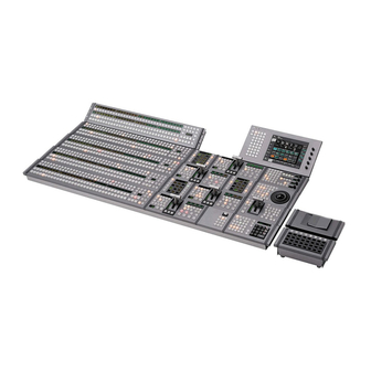
Page 17: Ccp-8000
It also have some module of DME control, Key Frame Control, Memory Card/USB, Flexi Pad and etc. The CCP-8000 consists of System Control Unit (MKS-8010), Menu Panel (MKS-8011), and Main Panel. System Control unit (MKS-8010) is a 3 rack unit chassis, which can be mounted in the standard 483 mm (19 inch) rack. - Page 18 1-3. System Description System control unit (MKS-8010) The system control unit provides control functions for the center control panel as a whole. It also supplies power to the various panels Shows the modules for CCP-8000. Model Name Description MKS-8013 32 AUX Bus Module...
- Page 19 1-3. System Description External dimensions of MKS-8010 132.4 17.5 SYSTEM CONTROL UNIT MKS-8010 POWER A POWER B Unit : mm 1-15 MVS-8000 System SYSTEM SETUP...
- Page 20 1-3. System Description External dimensions of main panel/AUX panel/menu panel MKS-8011 Unit : mm 1-16 MVS-8000 System SYSTEM SETUP...
- Page 21 1-3. System Description External dimensions of extension adaptor MKS-8075/memory card/USB adaptor MKS-8076 Unit : mm 1-17 MVS-8000 System SYSTEM SETUP...
- Page 22 1-3. System Description The MKS-8010 has a built-in cooling system consisting of a fan mounted on the both sides of the frame, and an air filter on the rear of the front panel. Cooling air is drawn in at the front side of the frame, through the filter, boards, and modules, and then expelled out the both sides of the frame at the fan unit.
- Page 23 1-3. System Description Power, control, and video connectors are at the rear of system control unit (MKS-8010), the main panel and menu panel (MKS-8011). The illustration below shows a full loaded rear board. MKS-8010 AC IN A, B REF IN connector GPI connector receptacle LTC IN connector...
- Page 24 1-3. System Description Power supply unit The CCP-8000 Power Supply Units is supplied with System Control Unit (MKS-8010). A power supply units is required to run the system. An optional second unit is added to provide redundant power. With second unit mounted, one unit can fail without causing system failure.
-
Page 25: Dcu-8000
1-3. System Description 1-3-4. DCU-8000 DCU-8000 is a 3 rack unit chassis which can be mounted in standard 483 mm (19 inch) rack. External dimensions of DCU-8000 Rack mount metal (supplied with RMM-10) 132.4 17.5 Unit : mm 1-21 MVS-8000 System SYSTEM SETUP... - Page 26 1-3. System Description The DCU-8000 has a built-in cooling system consisting of a fan mounted on the both sides of the frame, and an air filter on the rear of the front panel. Cooling air is drawn in at the front side of the frame, through the filter, boards, and modules, and then expelled out the both sides of the frame at the fan unit.
- Page 27 1-3. System Description DCU-8000 options The following lists the plug-in boards that may be purchased as options. DCU-8000 option configuration Front Side Option name Board name Slot No. Descriptions MKS-8701 RC-90 2 to 6 Tally/GPI output Board MKS-8702 IF-848 2 to 6 Serial Interface Board Rear side Option name...
-
Page 28: Mvs-8000 System Example
However, a single Ethernet switch can be used for connecting each LAN. For information about Ethernet switches that can be used in an MVS system, contact your local Sony Sales Office/Service Center. For detailed information about setting up the Ethernet switch, refer to the documentation supplied with the switch. -
Page 29: Functional Overview
1-5. Functional Overview 1-5. Functional Overview 1-5-1. Video Signal Flow DME Processor Pack MVE-8000 SWITCHER B SWITCHER A Reference video AC100 to 240 V Power Supply (*1) signal (*3) Reference video signal (*3) DME 1B DME 1A AC100 to 240 V Power Supply (*2) AC100 to 240 V Power Supply (*2) PRIMARY INPUTS 1 to 68... -
Page 31: Installation
Installation tasks should be completed in the following order: 1. Unpack equipment 2. Install the CCP-8000 main panel, the Menu Panel (MKS-8011) and the AUX panel (separate unit only) and System Control Unit (MKS-8010). 3. Install the switcher processor, DME processor, and DCU. -
Page 32: Mvs-8000 Installation
2-2. MVS-8000 Installation 2-2. MVS-8000 Installation 2. Rack mounting procedure This section describes the rack mounting procedure using 2-2-1. Rack Mounting the dedicated system rack mount kit of the MVS-8000. The MVS-8000 can be mounted in the 19-inch standard rack. Use the following torque to tighten the screws finally. - Page 33 2-2. MVS-8000 Installation 3. Attach the right and left brackets to the rack complete- 7. Place the right and left bottom ends of the MVS-8000 on ly using the specified eight screws. the support angles, and slide the equipment to the rear. (The illustration below shows the left bracket.) The support angles support the equipment as shown below.
-
Page 34: Mve-8000 Installation
2-3. MVE-8000 Installation 2-3. MVE-8000 Installation 2. Rack mounting procedure This section describes the rack mounting procedure using the RMM-10 rack mount kit. 2-3-1. Rack Mounting The MVE-8000 can be mounted in the 19-inch standard Tighten the screws to the following torque. rack. - Page 35 2-3. MVE-8000 Installation 3. Attach the right and left adaptors to the rack complete- 7. Fix the rack angle in the rack using the specified ly using the specified six screws. screws. (The illustration below shows the left adaptor.) Rack Rack angle 31.75 B4 x 10...
-
Page 36: Ccp-8000 Installation
2-4. CCP-8000 Installation 2-4. CCP-8000 Installation 2-4-1. Installation Space When the main panel or the AUX panel are embedded into a control console or the like, make holes as shown below into the control console with the following dimensions. Be sure to have an open space behind the cables of the connectors on the main panel shown as open space at “A”... - Page 37 2-4. CCP-8000 Installation Main panel/AUX panel configuration list MVS-8000 System SYSTEM SETUP...
-
Page 38: Installing The Main Panel
2-4. CCP-8000 Installation 2-4-2. Installing the Main Panel 3. Hold the main panel with the two persons or more and the remaining person installs the main panel into the control console while holding the main panel. When installing the main panel into the control console, be 4. -
Page 39: Installing The Aux Panel
. Screws (B3 x 5) : sure to install it with two persons or more. 4 pcs . EL table assemblies : 2 pcs (Sony Part No. : X-3167-779-1) Install the AUX panel by following the procedure de- scribed below. -
Page 40: Rack Mounting
2-4. CCP-8000 Installation 2-4-5. Rack Mounting 2. Rack mounting procedure This section describes the rack mounting procedure using the RMM-10 rack mount kit. Rack Mounting the System Control Unit MKS- 8010 The MKS-8010 is mounted in the 19-inch standard rack. - Page 41 2-4. CCP-8000 Installation 3. Attach the right and left adaptors to the rack complete- 7. Fix the rack angle in the rack using the specified ly using the specified six screws. screws. (The illustration below shows the left adaptor.) Rack...
- Page 42 2-4. CCP-8000 Installation 2. Rack mounting procedure Rack Mounting the MKS-8075 (Extension (1) Install the adaptor to the rack using rack mounting Adaptor)/MKS-8076 (Memory Card/USB Adaptor) screws (RK5 x 16) and washers as shown in the The MKS-8075 and MKS-8076 can be mounted in the 19- illustration.
-
Page 43: Dcu-8000 Installation
2-5. DCU-8000 Installation 2-5. DCU-8000 Installation 2. Rack mounting procedure This section describes the rack mounting procedure using 2-5-1. Rack Mounting the RMM-10 rack mount kit. The DCU-8000 can be mounted in the 19-inch standard rack. Tighten the screws to the following torque. To mount the DCU-8000 in the rack, use the specified rack Tightening torque : 120 x 10 N.m {12.2 kgf.cm}... - Page 44 2-5. DCU-8000 Installation 3. Attach the right and left adaptors to the rack complete- 7. Fix the rack angle in the rack using the specified ly using the specified six screws. screws. (The illustration below shows the left adaptor.) Rack Rack angle 31.75 B4 x 10...
-
Page 45: Mvs-8000 System Video Cabling
2-6. MVS-8000 system video Cabling 2-6. MVS-8000 System Video Cabling The MVS-8000 system connections is shown in the illustration. Different video and control wiring configurations may be created to meet individual facility requirements. Each input can be assigned to any CCP panel source select button, and any MVS system video signal can be assigned to any pair of output connectors. -
Page 46: Mvs-8000 System Control Cabling
2-7. MVS-8000 System Control Cabling 2-7-1. Cabling The MVS system uses Ethernet, serial, parallel, USB and S-BUS control. Tally and GPI control are also available from DCU-8000 and CCP-8000 (System Control Unit). MVS-8000 system control cabling Reference video signal (*2) - Page 47 2-7. MVS-8000 System Control Cabling Control cable length One Ethernet cable is available up to 100m from an Ethernet switch. Ethernet Switch Ethernet Switch 100 m 100 m 100 m 100 m 100 m 100 m MKS-8010 MVE-8000 MVS-8000 DCU-8000 Control LAN is 100 BASE-TX Ethernet Data LAN is 100 BASE-TX Ethernet Peripheral LAN is 100 BASE-TX Ethernet.
-
Page 48: Lan Requirements
2-7. MVS-8000 System Control Cabling 2-7-2. LAN Requirements The MVS-8000 system requires an Ethernet Local Area Network (LAN) for System Control LAN and Data LAN. Switcher Processor (MVS-8000), DME Processor (MKS-8800), and System Control Unit (MKS-8010) are all connected via an Ethernet switch of appropriate specification. Data LAN requires separate Ethernet switch from the one for Control LAN to avoid delay of the process- ing. -
Page 49: Ccp-8000 Panel Cabling
2-8. CCP-8000 Panel Cabling 2-8. CCP-8000 Panel Cabling CCP-8000 panel modules connections are shown in figure. CCP-8000 system control cabling Extension Adaptor MKS-8075 AUX panel Main panel HOST HOST SCU OUT (Max.5 m) SCU IN (Max.5 m) Reference video signal (Max.10 m) - Page 50 2-8. CCP-8000 Panel Cabling Panel cable length MKS-8010 System Control Unit Menu Panel 10 m AUX Panel (separate) MKS-8076 MKS-8075 10 m Main Panel MKS-8075 10 m MKS-8075 10 m Max. 30m MKS-8075 10 m MKS-8075 10 m MKS-8075 10 m...
- Page 51 2-8. CCP-8000 Panel Cabling The maximum number of modules that can be connected to a single MKS-8010 System Control Unit is as follows. The maximum number of adaptors that can be connected on 1 line is 8 units.) Model Model Name...
-
Page 52: Connecting The Mks-8075/Mks-8076
2-8. CCP-8000 Panel Cabling 2-8-1. Connecting the MKS-8075/MKS-8076 How to Connect the MKS-8075 and the MKS-8076 Structure of MKS-8075 . A maximum of eight extension adaptors can be connected by (Connecting the extension adaptor) using the horizontal connection and the vertical connection. - Page 53 2-8. CCP-8000 Panel Cabling When the Vertical connection is selected Connecting procedure (1) Connect the adaptor cases that you want to connect, together. 1. Remove the module cover. Remove the screws (BV3 (Be careful of the direction of the adaptor cases. See the x 10) fixing the caps (L) and (R), and remove the caps instruction given on the bottom of the adaptor case.)
- Page 54 2-8. CCP-8000 Panel Cabling (3) Fix the bottom plate of the adaptor cases at the loca- 7. For the connection methods (A) and (B) (see Fig. 2), tions shown in the illustration using the 4 connecting install the caps (L) and (R), and the module cover in screws (BV3 x 10) and the 2 pieces of the connecting the direction of the arrow.
- Page 55 2-8. CCP-8000 Panel Cabling Fig. 2 : Side panel installation methods FRONT FRONT Left side Connecting plate C FRONT FRONT Right side : Connecting plate screw fixing position : Side plate screw fixing position Connection method (A) FRONT FRONT Left side...
- Page 56 2-8. CCP-8000 Panel Cabling How to Connect the Cables Parts required . 50-pin cable supplied with the center control panel . 50-pin cable supplied with the MKS-8075 . USB cable (5 m) supplied with the center control panel Connecting cables for the MKS-8075 1.
-
Page 57: Configuration
The MVS-8000 system has three Ethernet connections for panel and devices communications (control, data, peripheral systems). The control LAN is intended to control the various devices from the center control panel (CCP-8000). The data LAN is intended to exchange of various type of data (key frame effects, snapshot, etc.) and still pictures of frame memory. -
Page 58: Ip Address
3-3. IP Address 3-3. IP Address The MVS-8000 system uses IP address 10.x.x.x. Each device of MVS-8000 system has independent NETWORK terminal for each LAN. The IP address for all NETWORK terminals has same rules as below. The IP address is identified by four byte of the form below. 10.AA.BB.CC ex. -
Page 59: Default Ip Address
3-3. IP Address 3-3-1. Default IP Address The MVS-8000 system is shipped with default IP addresses. Sony Corporation has chosen these default IP addresses to make MVS-8000 system configuration easy. Device IP Address Host name Dipswitch setting Group ID Unit ID MVS-8000 10.1.2.1 (C) -
Page 60: Changing Ip Address
Device Board Group ID Unit ID MVS-8000 CA-44 S102 (8bit) S103 (8bit) MVE-8000 CA-44CF S102 (8bit) S103 (8bit) CCP-8000 CA-45 S902 (8bit) S901 (8bit) DCU-8000 CA-47 S754 (8bit) S755 (8bit) Dipswitch on CPU board Group ID Unit ID OPEN OPEN... -
Page 61: Ethernet Switch Settings
3-4. Ethernet Switch Settings 3-4. Ethernet Switch Settings The following Ethernet switches are tested to MVS-8000 system. Recommended models Vendor Model name Cisco Catalyst 29xx-XL Cisco Catalyst 35xx-XL Cisco Catalyst 4000 series Cisco Catalyst 5000 series * : Please confirm the details of a recommendation model 1 to a Cisco agency. The Ethernet switch for MVS-8000 system requires the following settings Follow the flowchart below to setup Ethernet switch. - Page 62 3-4. Ethernet Switch Settings A) Initialize ethernet switch Cisco Catalyst 29xx-XL series or Cisco Catalyst 35xx-XL series require the following parameters to initialize. For details, refer to Quick Start Guide supplied with a Ethernet switch If the following network configuration does not fit your existing Ethernet configuration, make sure all nodes have unique node address and are place on the appropriate network.
- Page 63 3-4. Ethernet Switch Settings B) Set VLAN In Case of Cisco Catalyst 2900-XL Series or Cisco Catalyst 3500-XL Series VLAN is set on network through a standard browser such as Microsoft Internet Explorer or Netscape Navigator/Communicator. For details, refer to Quick Start Guide supplied with an Ethernet switch. Step 1 : Disable Cisco Discovery Protocol (CDP) To disable CDP requires Cisco Command Line Interface (CLI).
- Page 64 3-4. Ethernet Switch Settings In Case of Cisco Catalyst 4000 Series or Cisco Catalyst 5000 Series The settings require Cisco Command Line Interface (CLI). For details of operation, refer to Family Software Configuration Guide of Catalyst 4000 series or Cisco Catalyst 5000 series.
-
Page 65: Software Installation
3-4. Ethernet Switch Settings 3-5. Software Installation 3-6. Engineering Setups Step 4 : Disable Spanning-Tree Disable all spanning tree on VLAN. Refer to Catalyst 4000/5000 Family Software Configuration Guide Step 5 : Assign sc0 to VLAN Assign sc0 to VLAN except Control LAN, Data LAN, and Peripheral LAN. Refer to Catalyst 4000/5000 Family Software Configuration Guide Step 6 : Disable Cisco Discovery Protocol (CDP) Disable CDP globally. -
Page 66: Tally Setup
The system that is configured by the combination of MVS-8000 system with the Sony routing switcher *1 : The equipment before Ver. 1.20 requires primary station. (Sony S-BUS Routing Switcher or BKPF-R70A is required.) In the case if the equipment of Ver. 1.30 and higher is not connected to router, set the primary station function of the MVS-8000 to the ON position. - Page 67 3-7. Tally Setup Confirming the setting items The following items marked with the white round circle are required to be set in the respective systems. O = Setting is required. System 1 System 2 System 3 Switcher Output Assignment Router O (default) Group Tally Wiring...
-
Page 68: Setting Router
3-7. Tally Setup 3-7-1. Setting Router Engineering Setup → Router/Tally → Router Page 7361 This menu is used to assign the input and output signals of the switcher on the virtual matrix space of the S-BUS. When setting the tallies, the input and output signals to and from the equipment (such as router, switcher and others) that has the crosspoints should be assigned on the virtual matrix space. - Page 69 3-7. Tally Setup Setting items System 1 System 2 System 3 Device SWR1/SWR2 SWR1/SWR2 SWR1/SWR2 Matrix Size Standard Standard Standard/Compact Setting Setting Setting Source Source Source 1 to Max (889 (S), 897 (C)) Destination Destination Destination : 1 to Max (887 (S), 897 (C)) Level : Level : Level :...
- Page 70 3-7. Tally Setup Setup example : For the system 3 System : MVS-8000 x 1 unit, router x 1 unit (8 x 4) The MVS-8000 is assigned to (virtual source No. 19 to No. 146 and virtual destination No. 12 to No. 139) on the virtual matrix space. Select “Compact”...
- Page 71 3-7. Tally Setup Input 1024 1 2 3 4 5 6 7 8 9 10 1112 1314 15 1617 18 19 20 2122 23 2425 26 1 2 3 4 5 6 7 Router 1 2 3 4 5 6 Output (SWR1) Virtual matrix...
- Page 72 3-7. Tally Setup MVS-8000 matrix assignment (Standard mode) Source Source Source Primary 1 Primary 41 Primary 2 Primary 42 Primary 3 Primary 43 Primary 4 Primary 44 Primary 5 Primary 45 Primary 6 Primary 46 Primary 7 Primary 47 Primary 8 Primary 48 Primary 9 Primary 49...
- Page 73 3-7. Tally Setup Source Source Black P/P Out 4 White P/P Out 5 Color Bkgd 1 P/P Out 6 Color Bkgd 2 P/P Proc Video Frame Memory 1 P/P Proc Key Frame Memory 2 DME1 Frame Memory 3 DME2 Frame Memory 4 DME3 Frame Memory 5 DME4...
- Page 74 3-7. Tally Setup Destination * * * * * Destination * * * * * Destination Out 43 Assignable Output Out 1 Assignable Output Out 2 Assignable Output Out 44 Assignable Output Out 45 Assignable Output Out 3 Assignable Output Out 4 Assignable Output Out 46...
- Page 75 3-7. Tally Setup Destination * * * * * Destination * * * * * M/E-2 Dme Key DME 3 Key M/E-2 Ext Dme DME 4 Video M/E-3 Bkgd A DME 4 Key M/E-3 Bkgd B DME 5 Video M/E-3 Utility 1 DME 5 Key M/E-3 Utility 2 DME 6 Video...
- Page 76 3-7. Tally Setup MVS-8000 matrix assignment (Compact mode) Source Source Source Primary 1 Primary 41 Primary 2 Primary 42 Primary 3 Primary 43 Primary 4 Primary 44 Primary 5 Primary 45 Primary 6 Primary 46 Primary 7 Primary 47 Primary 8 Primary 48 Primary 9 Primary 49...
- Page 77 3-7. Tally Setup Source Source Black DME4 White DME5 Color Bkgd 1 DME6 Color Bkgd 2 DME7 Frame Memory 1 DME8 Frame Memory 2 Frame Memory 3 Frame Memory 4 Frame Memory 5 Frame Memory 6 Frame Memory 7 Frame Memory 8 Color Correction 1 Color Correction 2 DME Monitor Video...
- Page 78 3-7. Tally Setup Destination * * * * * Destination * * * * * Destination Out 43 Assignable Output Out 1 Assignable Output Out 44 Assignable Output Out 2 Assignable Output Out 45 Assignable Output Out 3 Assignable Output Out 46 Assignable Output Out 4...
- Page 79 3-7. Tally Setup Destination * * * * * Destination * * * * * M/E-3 Key 1 Fill * : To switch the XPT from the S-Bus remote control, select the corre- M/E-3 Key 1 Source sponding bus number. M/E-3 Key 2 Fill ** : This is the output (bus) that is set by the Output Assign of the switcher setup.
-
Page 80: Setting Group Tally
3-7. Tally Setup 3-7-2. Setting Group Tally Engineering Setup → Router/Tally → Group Tally Page 7362 This menu is used to select either the tally groups 1 to 4 or the tally groups 5 to 8 shall be used by as many as the four tally groups at the maximum. - Page 81 3-7. Tally Setup Setting items System 1 System 2 System 3 Tally Gp Gp1-4/Gp5-8 Gp1-4/Gp5-8 Gp1-4/Gp5-8 SBus Tally Enable Disable Disable Enable/Disable For the system 1 Select “Gp1-4” or “Gp5-8” as desired from the Tally Group for the system 1. As to the S-Bus Tally, select “Disable”...
-
Page 82: Setting Wiring
3-7. Tally Setup 3-7-3. Setting Wiring Engineering Setup → Router/Tally → Wiring Page 7363 This menu is set in order to trace back the connection and to locate the source of the connected equipment starting from the output of the final stage. In the system configuration where inputs and outputs of a switcher are connected to a router, the connec- tion relationship (wiring) between the switcher and the router on the matrix space must be set. - Page 83 3-7. Tally Setup Setup example : For the system 3 System : MVS-8000 x 1 unit, router x 1 unit (8 x 4) 1. Connect Destination 1 (virtual No. 5) of a router to Primary 1 (virtual No. 19) of the MVS-8000. 2.
- Page 84 3-7. Tally Setup Input CAM1 CAM2 CAM3 CAM4 CAM5 CAM6 VTR1 VTR2 1024 1 2 3 4 5 6 7 8 9 10 1112 1314 15 16 1718 19 20 2122 23 2425 26 1 2 3 4 5 6 7 Router 1 2 3 4 5 6 On Air...
-
Page 85: Setting Tally Enable
3-7. Tally Setup 3-7-4. Setting Tally Enable Engineering Setup → Router/Tally → Tally Enable Page 7364 This menu is used to set which Destination should be output to which tally. In the video switching systems, there are many occasions that two or more independent jobs are carried out by the same switching system. - Page 86 3-7. Tally Setup Setting items System 1 System 2 System 3 Tally Enable Setting is required Setting is not required Setting is required Tally Type : G1 to 8, R1 to 8 Tally Type : G1 to 8, R1 to 8 Enable : Enable, Disable, Enable :...
- Page 87 3-7. Tally Setup Input CAM1 CAM2 CAM3 CAM4 CAM5 CAM6 VTR1 VTR2 1 2 3 4 5 6 7 8 9 10 1112 13 14 1516 1718 19 20 2122 23 2425 26 1024 1 2 3 4 5 6 7 Router 1 2 3 4 5 6 On Air...
-
Page 88: Setting Tally Copy
3-7. Tally Setup 3-7-5. Setting Tally Copy Engineering Setup → Router/Tally → Tally Copy Page 7365 This menu is used to unify the tally information. The virtual sources correspond to sources by one-to-one correspondence. However, there are cases that the same source is connected to two or more input terminals at the same time. For example, the ordinary video output signal and the video output signal with timecode from a single unit of VTR are connected to the separate input terminals respectively. - Page 89 3-7. Tally Setup Setting items System 1 System 2 System 3 Tally Copy Setting is required Setting is not required Setting is required For the system 1 Set the virtual terminal number of copy source (From Source) and copy destination (To Source) as required.
- Page 90 3-7. Tally Setup Input CAM1 CAM2 CAM3 CAM4 CAM5 CAM6 VTR1 VTR2 With Without Unifications 1 2 3 4 5 6 7 8 9 10 1112 1314 1516 1718 19 20 2122 23 2425 26 1024 1 2 3 4 5 6 7 Router 1 2 3 4 5 6 On Air...
-
Page 91: Setting Parallel Tally
3-7. Tally Setup 3-7-6. Setting Parallel Tally Engineering Setup → Router/Tally → Parallel Tally Page 7366 The Parallel Tally output provides the relay contact. This menu is used to enable the Parallel Tally to directly turn ON/OFF the tally lamp. In this setting, terminal numbers of the virtual inputs and the virtual outputs (Monitor Tally) of the virtual matrix are assigned to the respective pins of the parallel tally connector (DCU-8000). - Page 92 3-7. Tally Setup Setup example : For the system 3 System : MVS-8000 x 1 unit, router x 1 unit (8 x 4) 1. Put the Red/Green Tally to the CAM 1 to CAM 3 (virtual terminals Nos. 7 to 9) that supply video signal to the router.
-
Page 93: Setting Serial Tally
In Ver. 1.20, the fixed tallies of R-1, G-1, R-2 and G-2 are output from Serial Tally 1 terminal of the MKS-8700. Tally signal is output according to the protocol attached as APPENDIX. For details, please refer to the “BVS-3000 Series, DVS-8000 Series PROTOCOL and COMMAND SPECIFICATIONS (Sony Part No. : 9-967-262-21)”. Bit assignment is shown in the following table. - Page 94 3-7. Tally Setup Bit No. Source Bit No. Source Primary 71 M/E-3 Out 6 Primary 72 P/P Out 1 Primary 73 P/P Out 2 Primary 74 P/P Out 3 Primary 75 P/P Out 4 Primary 76 P/P Out 5 Primary 77 P/P Out 6 Primary 78 DME1...
- Page 95 3-7. Tally Setup APPENDIX **************** MVS SERIAL TALLY **************** EFF:EFFECT ADDRESS 24h:SERIAL TALLY <<PGM TALLY>> WRITE: BC, EFF, byte2, FF, byte4, byte5, byte6, ... byte2 TALLY TYPE 91h: GP1 RED 92h: GP1 GREEN 93h: GP2 RED 94h: GP2 GREEN 95h: GP3 RED 96h: GP3 GREEN 97h: GP4 RED 98h: GP4 GREEN...
- Page 96 3-7. Tally Setup 1-128 means each source number. It’s assignable, but the default is the same as MVS source number specified in COMPACT MODE. If it’s tallied, the bit is “1”. If it’s not tallied, it’s “0”. Status bit shows if the data is all “0” or not. If it’s all “0”, the status bit is “0”.
-
Page 97: Pin Output
3-8. Pin Output 3-8. Pin Output Pin No. Signal name Function GPI OUT 6 General-purpose relay 3-8-1. MVS-8000 output (B) (*4) GPI OUT 8 GPI OUT COM Ground for open collector The input/output signals of the connectors at the rear panel output are as follows. - Page 98 3-8. Pin Output REMOTE 1 to 4 : RS-422A (D-sub 9-pin, Female) <DEVICE> (*5) from External Devices _ EXT VIEW _ Pin No. Signal name Function Frame ground Transmitted data (_) Received data (+) Common ground No Connection Common ground Transmitted data (+) Received data (_) No Connection...
-
Page 99: Mve-8000
3-8. Pin Output 3-8-2. MVE-8000 GPI : (D-sub 25-pin, Female) INPUT x 8, TTL OUTPUT x 4, relay contacts 30 V 0.1 A The input/output signals of the connectors at the rear panel (resistive load) are as follows. OUTPUT x 4, open collector 30 V rated voltage <CONTROLLER>... -
Page 100: Ccp-8000
3-8. Pin Output 3-8-3. CCP-8000 Pin No. Signal name Function GPI OUT 6 General-purpose open collector Input and output signals of the connectors on the rear panel output (B) (*2) GPI OUT 8 are as follows. GPI OUT COM Ground for open collector output... - Page 101 3-8. Pin Output EDITOR PANEL : RS-422A (D-sub 9-pin, Female) EXT DISPLAY : (High-density D-sub 15-pin, analog (*3) <CONTROLLER> RGB, Female) to External Display _ EXT VIEW _ EXT VIEW Pin No. Signal name Function Pin No. Signal name Function Frame ground Video Red Received data (_)
-
Page 102: Dcu-8000
3-8. Pin Output 3-8-4. DCU-8000 TALLY/GPI IN 1-34 : D-sub 37-pin, Female INPUT x 34, TTL, 2 INPUT TTL/+12 V Switchable (*2) The input/output signals of the connectors at the rear panel are as follows. _EXT VIEW_ <CONTROLLER> indicates a controlling device. <DEVICE>... - Page 103 3-8. Pin Output TALLY/GPI IN 35-68 : D-sub 37-pin, Female TALLY/GPI IN 69-102 : D-sub 37-pin, Female INPUT x 34, TTL, 2 INPUT TTL/+12 V Switchable (*2) INPUT x 34, TTL, 2 INPUT TTL/+12 V Switchable (*2) _EXT VIEW_ _EXT VIEW_ Pin No.
- Page 104 3-8. Pin Output MKS-8701 TALLY/GPI OUT 1-18 : D-sub 37-pin, Female OUTPUT x 18, relay contacts 30 V 0.1 A (*3) _EXT VIEW_ Pin No. Signal name Function Pin No. Signal name Function TALLY/GPI OUT 1A Tally/GPI outputs TALLY/GPI OUT 11B Tally/GPI outputs TALLY/GPI OUT 2A TALLY/GPI OUT 12B...
- Page 105 3-8. Pin Output TALLY/GPI OUT 19-36 : D-sub 37-pin, Female OUTPUT x 18, relay contacts 30 V 0.1 A (*3) _EXT VIEW_ Pin No. Signal name Function Pin No. Signal name Function TALLY/GPI OUT 19A Tally/GPI outputs TALLY/GPI OUT 29B Tally/GPI outputs TALLY/GPI OUT 20A TALLY/GPI OUT 30B...
- Page 106 3-8. Pin Output TALLY/GPI OUT 37-54 : D-sub 37-pin, Female OUTPUT x 18, relay contacts 30 V 0.1 A (*3) _EXT VIEW_ Pin No. Signal name Function Pin No. Signal name Function TALLY/GPI OUT 37A Tally/GPI outputs TALLY/GPI OUT 47B Tally/GPI outputs TALLY/GPI OUT 38A TALLY/GPI OUT 48B...
- Page 107 3-8. Pin Output MKS-8702 REMOTE1 to 6 : RS-422A (D-sub 9-pin, Female) <CONTROLLER> to External Device _ EXT VIEW _ Pin No. Signal name Function Frame ground Received data (_) Transmitted data (+) Common ground No Connection Common ground Received data (+) Transmitted data (_) No Connection 3-51...
-
Page 109: Specifications
Section 4 Specifications The following specifications show the reference performance for this unit and individual option boards/ units. Design and specifications are subject to change without notice. 4-1. MVS-8000 MVS-8000 Multi Format Switcher Processor General 100 to 240 V AC ± 10 %, 50/60 Hz Power requirements Peak inrush current (1) Power ON, current probe method : 60 A (100 V), 110 A (230 V) - Page 110 4-1. MVS-8000 Reference input and output BNC type, 75 Z with loop-through output REF IN HDTV systems : HD tri-level sync/SDTV analog black burst/SDTV analog sync SDTV systems : Analog black burst/analog sync BNC type, 75 Z REF OUT HD tri-level sync (HDTV systems only) Signal level 300 mV ±...
- Page 111 4-1. MVS-8000 MKS-8110SD 17 Input Board General Power requirements 12 V DC Power consumption Max. 10 W 274 x 94 mm (10 Dimensions inches) (w/d) Mass Approx. 1 kg (2 lb 3 oz) Input Inputs 17 (BNC type) Signal format SMPTE259M-C 0.8 V p-p ±10 % Signal level...
- Page 112 4-1. MVS-8000 MKS-8160HD 8 Output Board General Power requirements 12 V DC Power consumption Max. 110 W OUT board : 317 x 380 mm (12 x 15 inches) (w/d) Dimensions CN board : 274 x 94 mm (10 inches) (w/d) Mass Approx.
- Page 113 4-1. MVS-8000 MKS-8161HD Monitor Output Board General Power requirements 12 V DC Power consumption Max. 10 W 274 x 94 mm (10 Dimensions inches) (w/d) Mass Approx. 1 kg (2 lb 3 oz) Output Outputs 8 (BNC type), each with 2 outputs Signal format SMPTE292M 0.8 V p-p ±...
- Page 114 4-1. MVS-8000 MKS-8170HD DME Interface Board General Power requirements 12 V DC Power consumption Max. 50 W DIF board : 317 x 380 mm (12 x15 inches) (w/d) Dimensions CN board : 274 x 94 mm (10 inches) (w/d) Mass Approx.
- Page 115 4-1. MVS-8000 MKS-8210SD Mix/Effect Board Set General Power requirements 12 V DC Power consumption Max. 150 W MIX board : 317 x 380 mm (12 x 15 inches) (w/d) Dimensions KPC board : 317 x 380 mm (12 x 15 inches) (w/d) DI board : 317 x 380 mm (12 x 15 inches) (w/d) DO board : 317 x 380 mm (12...
- Page 116 4-1. MVS-8000 HK-PSU04 Power Supply Unit General 100 to 240 V AC ± 10 %, 50/60 Hz Power requirements 12 V DC ± 0.5 V Output power Power consumption 10 to 5 A Secondary power supply Max. 60 A Dimensions 94 x 83 x 396 mm (3 x 15 inches) (w/h/d)
- Page 117 4-2. MVE-8000 4-2. MVE-8000 MKS-8800 Multi Format DME Processor General 100 to 240 V AC ± 10 %, 50/60 Hz Power requirements Peak inrush current (1) Power ON, current probe method : 60 A (100 V), 60 A (230 V) (2) Hot switching inrush current, measured in accordance with European standard EN55103-1 : 40 A (230 V) Power consumption...
- Page 118 4-2. MVE-8000 MKS-8810M Basic Effects Board General Power requirements 12 V DC Power consumption Approx. 4.3 A 317 x 380 mm (12 x 15 inches) (w/d) Dimensions Mass Approx. 1.1 kg (2 lb 6 oz) Accessories supplied Operation and Installation Guide (1) (supplied only when product is purchased separately) MKS-8820M Input/Output Board General...
- Page 119 4-3. DCU-8000 4-3. DCU-8000 MKS-8700 Device Control Unit General 100 to 240 V AC ± 10 %, 50/60 Hz Power requirements Peak inrush current (1) Power ON, current probe method : 20 A (100 V), 60 A (230 V) (2) Hot switching inrush current, measured in accordance with European standard EN55103-1 : 30 A (230 V) Power consumption Max.
- Page 120 4-3. DCU-8000 MKS-8701 TALLY/GPI Output Board General Power requirements 12 V DC Power consumption Max. 1 A RC board : 317 x 380 mm (12 x 15 inches) (w/d) Dimensions CN board : 278 x 94 mm (11 x 3 inches) (w/d) Mass Approx.
- Page 121 4-4. CCP-8000 4-4. CCP-8000 Center Control Panel The center control panel is comprised of the main panel, the System Control Unit (MKS-8010), the menu panel (MKS-8011), and operation modules. The required operation modules are installed in the main panel at the factory.
- Page 122 4-4. CCP-8000 Main Panel Main panel specifications vary according to the system configuration. The following shows specifications for typical configurations. General Power requirements 12 V DC Power consumption Max. 10 A +5 dC to +40 dC (41 dF to 104 dF)
- Page 123 4-4. CCP-8000 AUX Panel AUX panel specifications vary according to the system configuration. The following shows specifications for typical configurations. General Dimensions (w/h/d) Example 1 : (32 crosspoint buttons) : 782 x 82 x 132 mm (30 inches) Example 2 : (24 crosspoint buttons) :...
- Page 124 4-4. CCP-8000 Control connectors CTRL RJ-45 Complies with 100BASE-TX standard DATA RJ-45 Complies with 100BASE-TX standard PERIPH RJ-45 Complies with 100BASE-TX standard MAIN PANEL D-sub 50-pin, female MENU PANEL D-sub 50-pin, female EXT PANEL 1, 2, 3 D-sub 50-pin, female...
- Page 125 4-4. CCP-8000 MKS-8011 Menu Panel General Power requirements 12 V DC Power consumption Max. 1A 424 x 46 x 220 mm (16 Dimensions inches) (w/h/d, excluding projections) Mass Approx. 2.5 kg (5 lb 8 oz) Control connectors D-sub 50-pin, female...
- Page 126 4-4. CCP-8000 MKS-8017 32 XPT Module General Power requirements 12 V DC Power consumption Max. 3 A 740 x 132 mm (29 Dimensions inches) (w/d, excluding projections) Mass Approx. 2.5 kg (5 lb 8 oz) Accessories supplied Operation and Installation Guide (1)
- Page 127 4-4. CCP-8000 MKS-8021 Simple Transition Right Module General Power requirements 12 V DC Power consumption Max. 1 A 293 x 132 mm (11 Dimensions inches) (w/d, excluding projections) Mass Approx. 1.0 kg (2 lb 3 oz) Accessories supplied Operation and Installation Guide (1)
- Page 128 4-4. CCP-8000 MKS-8025 Memory Card/USB Module General Power requirements 5 V DC Power consumption Max. 1 A 220 x 132 mm (8 Dimensions inches) (w/d, excluding projections) Mass Approx. 0.7 kg (1 lb 8 oz) PC card slot Type II (1) (Supports Card Bus)
- Page 129 4-4. CCP-8000 MKS-8031JS Joystick Module General Power requirements 12 V DC Power consumption Max. 1 A 220 x 132 mm (8 Dimensions inches) (w/d, excluding projections) Mass Approx. 0.7 kg (1 lb 8 oz) Accessories supplied Operation and Installation Guide (1)
- Page 130 4-4. CCP-8000 MKS-8034FB FTB Module General Power requirements 12 V DC Power consumption Max. 0.5 A 147 x 132 mm (5 Dimensions inches) (w/d, excluding projections) Mass Approx. 0.4 kg (14 oz) Accessories supplied Operation and Installation Guide (1) (supplied only when product is purchased separately)
- Page 131 4-4. CCP-8000 MKS-8075 Extension Adaptor General Power requirements 12 V DC Power consumption Max. 0.5 A 263 x 79 x 132 mm (10 Dimensions inches) (w/h/d, excluding projections) Mass Approx. 0.9 kg (1 lb 15 oz) Control connectors EXT IN...
- Page 133 The material contained in this manual consists of information that is the property of Sony Corporation. Sony Corporation expressly prohibits the duplication of any portion of this manual or the use thereof for any purpose other than the operation or maintenance of the equipment described in this manual without the express written permission of Sony Corporation.
- Page 134 Printed in Japan Sony Corporation MVS-8000 (SY) E 2002. 4 16 B&P Company 9-967-961-01 ©2002...