
Related Manuals for Toro 74448


Summary of Contents for Toro 74448
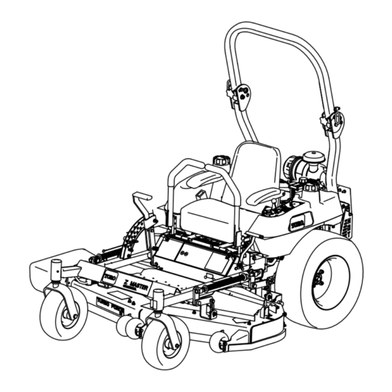
- Page 1 Form No. 3359-436 Rev B Z400 Z Master with a 48in or 52in 7-Gauge Side Discharge Mower Model No. 74448—Serial No. 280000001 and Up Model No. 74449—Serial No. 280000001 and Up Register at www.Toro.com. Original Instructions (EN)
-
Page 2: Table Of Contents
Whenever you need service, genuine Toro parts, or worthy of special attention. additional information, contact an Authorized Service Dealer or Toro Customer Service and have the model and serial numbers of your product ready. Figure 1 Contents identifies the location of the model and serial numbers on the product. - Page 3 Using the Rollover Protection System Setting the Hydraulic Pump Neutral (ROPS) ............13 Position............41 Think Safety First ..........14 Mower Deck Maintenance ........43 Operating the Parking Brake ....... 15 Leveling the Mower at Three Positions ....43 Starting and Stopping the Engine ......16 Servicing the Cutting Blades .......
-
Page 4: Safety
Safety • Use extra care when handling gasoline and other fuels. They are flammable and vapors are explosive. Improper use or maintenance by the operator or owner – Use only an approved container can result in injury. To reduce the potential for injury, –... -
Page 5: Slope Operation
• Be certain that the seat belt can be released quickly decals. in the event of an emergency. • Be aware there is no rollover protection when the • Use only Toro approved attachments. Warranty may roll bar is down. be voided if used with unapproved attachments. -
Page 6: Slope Chart
Slope Chart... -
Page 7: Safety And Instructional Decals
Safety and Instructional Decals Safety decals and instructions are easily visible to the operator and are located near any area of potential danger. Replace any decal that is damaged or lost. 58-6520 1. Grease 1-403005 66-1340 1-523552 65-2690 1-633818 68-8340 98-4387 54-9220 1. - Page 8 98-5954 107-1687 103-2644 Battery Symbols Some or all of these symbols are on your battery 1. Explosion hazard 6. Keep bystanders a safe 105-7798 distance from the battery. 2. No fire, open flame, or 7. Wear eye protection; smoking. explosive gases can cause blindness and other injuries 8.
- Page 9 108-1050 107-2102 108-1051 Manufacturer’s Mark 1. Indicates the blade is identified as a part from the original machine manufacturer. 107-2112...
-
Page 10: Product Overview
107-8445 107-9309 1. Warning—read the Operator’s Manual for information on charging the battery; contains lead; do not discard. 2. Read the Operator’s Manual. 108-5995 1. Fast 3. Neutral 4. Reverse 2. Slow 110-0439 1. Choke 3. Engine—run 5. Fast 7. Slow 2. -
Page 11: Controls
Contact your Authorized Service Dealer or Distributor or go to www.Toro.com for a list of all approved attachments and accessories. Using the Fuel Shutoff Valve Figure 4 1. -
Page 12: Operation
Operation Note: Determine the left and right sides of the machine from the normal operating position. Adding Fuel Use Unleaded Regular Gasoline suitable for automotive use (85 pump octane minimum). Leaded regular gasoline may be used if unleaded regular is not available. -
Page 13: Checking The Engine Oil Level
Important: Do not use fuel additives containing methanol or ethanol. In certain conditions during fueling, static Add the correct amount of gas stabilizer/conditioner electricity can be released causing a spark to the gas. which can ignite the gasoline vapors. A fire Note: A fuel stabilizer/conditioner is most effective or explosion from gasoline can burn you and when mixed with fresh gasoline. -
Page 14: Think Safety First
Important: Always use the seat belt with the roll bar in the raised position. There is no rollover protection when the roll bar is in the down position. • Lower the roll bar only when absolutely necessary. • Do not wear the seat belt when the roll bar is in the down position. -
Page 15: Operating The Parking Brake
Operating on wet grass or steep slopes can This machine produces sound levels in excess cause sliding and loss of control. of 85 dBA at the operators ear and can cause hearing loss through extended periods of Wheels dropping over edges can cause rollovers, exposure. -
Page 16: Starting And Stopping The Engine
Figure 13 Figure 11 1. Choke—on 2. Choke—off 1. Parking brake-ON 3. Brake Stop 2. Parking brake-OFF 5. Move the throttle control to the Fast position before starting a cold engine (Figure 14). Starting and Stopping the Engine Starting the Engine 1. -
Page 17: Operating The Power Take Off (Pto)
Engaging the PTO 1. If the engine is cold, allow the engine to warm up 5 to 10 minutes before engaging the PTO. 2. While seated in the seat, release the pressure on the traction control levers and place in neutral. 3. -
Page 18: Driving Forward Or Backward
• You are sitting on the seat. • The parking brake is engaged. Machine can spin very rapidly. Operator may • The power take off (PTO) is disengaged. lose control of machine and cause personal injury or damage to machine. •... -
Page 19: Stopping The Machine
Children or bystanders may be injured if they move or attempt to operate the tractor while it is unattended. Always remove the ignition key and set the parking brake when leaving the machine unattended, even if just for a few minutes. Adjusting the Height-of-Cut The height-of-cut is adjusted from 1-1/2 to 4-1/2 inch (38 to 114 mm) in 1/4 inch (6 mm) increments by... -
Page 20: Positioning The Seat
2. Stop the engine, remove the key, and wait for all moving parts to stop before leaving the operating position. 3. After adjusting the height-of-cut, adjust the rollers by removing the flange nut, bushing, spacer, and bolt (Figure 19 , Figure 20 and Figure 45 ). Note: The two middle rollers will not have a spacer (Figure 20). -
Page 21: Pushing The Machine By Hand
Figure 23 Figure 22 1. Side console controls 3. Hydraulic pumps 1. Seat latch 3. Seat 2. Fuel cap 2. By-pass valve Using the Side Discharge Pushing the Machine by Hand The mower has a hinged grass deflector that disperses Important: Always push the machine by hand. -
Page 22: Loading Machines
To transport the machine: • Lock the brake and block the wheels. Loading a unit onto a trailer or truck increases • Securely fasten the machine to the trailer or truck the possibility of backward tip-over and could with straps, chains, cable, or ropes. cause serious injury or death. -
Page 23: Blade Maintenance
If a blade is damaged or worn, replace it immediately with Mow at Correct Intervals a genuine TORO replacement blade. Normally, mow every four days. But remember, grass grows at different rates at different times. So to maintain the same cutting height, which is a good practice, mow more often in early spring. -
Page 24: Maintenance
Maintenance Recommended Maintenance Schedule(s) Maintenance Service Maintenance Procedure Interval • Change the engine oil. After the first 8 hours • Check the hydraulic fluid. • Change the hydraulic filter. After the first 25 hours • Check the safety system. • Check the engine oil level. •... -
Page 25: Greasing The Mower Deck And Belt Idlers
How to Grease Where to Add Light Oil or Spray Lubrication 1. Disengage the PTO, move the motion control levers to the neutral locked position and set the parking Service Interval: Every 150 hours brake. • Seat switch actuator. 2. Stop the engine, remove the key, and wait for all moving parts to stop before leaving the operating •... -
Page 26: Engine Maintenance
Engine Maintenance Servicing the Air Cleaner Note: Service the filter more frequently if operating conditions are extremely dusty or sandy. Removing the Filters 1. Disengage the PTO, move the motion control levers to the neutral locked position and set the parking brake. -
Page 27: Servicing The Engine Oil
1. If installing a new filter, check it for shipping damage. Do not use a damaged filter. 2. Carefully slide the air filter into the body (Figure 27). Note: Ensure that it is fully seated by pushing on the outer rim of the filter while installing it. Important: Do not press on the soft inside area of the filter. -
Page 28: Servicing The Spark Plugs
3. Apply a thin coat of new oil to the rubber gasket on the replacement filter (Figure 31). 4. Install the replacement oil filter to the filter adapter, turn the oil filter clockwise until the rubber gasket contacts the filter adapter, then tighten the filter an additional 3/4 turn (Figure 31). -
Page 29: Fuel System Maintenance
Checking the Spark Plugs Fuel System Service Interval: Every 100 hours Maintenance 1. Look at the center of the spark plugs (Figure 33). If you see light brown or gray on the insulator, the Replacing the Fuel Filter engine is operating properly. A black coating on the insulator usually means that the air cleaner is dirty. -
Page 30: Servicing The Fuel Tank
Servicing the Fuel Tank Electrical System Maintenance In certain conditions, gasoline is extremely Servicing the Battery flammable and highly explosive. A fire or explosion from gasoline can burn you and Warning others and can damage property. • Drain gasoline from the fuel tank when the CALIFORNIA engine is cold. -
Page 31: Installing The Battery
6. Remove both wing nuts (1/4 inch) securing the battery clamp (Figure 35). Incorrect battery cable routing could damage 7. Remove the battery. the machine and cables causing sparks. Sparks can cause the battery gasses to explode, Installing the Battery resulting in personal injury. -
Page 32: Servicing The Fuses
Figure 36 1. Positive Battery Post 3. Red (+) Charger Lead 2. Negative Battery Post 4. Black (-) Charger Lead Figure 37 1. Main, 30 amp 4. Ignition switch 3. Install the battery in the machine and connect the 5. Throttle lever 2. -
Page 33: Drive System Maintenance
Drive System Check the pressure at the valve stem (Figure 39). Maintain the air pressure in the front and rear tires at Maintenance 13 psi (90 kPa). Uneven tire pressure can cause uneven cut. Check the tires when they are cold to get the most Adjusting the Tracking accurate pressure reading. -
Page 34: Adjusting The Caster Pivot Bearing
Figure 40 1. Slotted Nut 3. Hole in threaded shaft 2. Two threads or less 4. Washer (if needed) showing 5. Check the distance from bottom of slot in nut to inside edge of hole. Two threads or less should be showing (Figure 40). -
Page 35: Cooling System Maintenance
Cooling System Maintenance Cleaning the Air Intake Screen Service Interval: Before each use or daily—Clean the engine air intake screen from grass and debris. Before each use remove any build-up of grass, dirt or other debris from the cylinder and cylinder head cooling fins, air intake screen on flywheel end, and carburetor-governor levers and linkage. -
Page 36: Brake Maintenance
Brake Maintenance Belt Maintenance Adjusting the Parking Brake Inspecting the Belts Check the parking brake for proper adjustment. Service Interval: Every 100 hours 1. Disengage the brake lever (lever down). Check belts for cracks, frayed edges, burn marks or any 2. -
Page 37: Replacing The Pump Drive Belt
Replacing the Pump Drive Belt Service Interval: Every 50 hours 1. Remove the mower belt first; refer to Replacing the Mower Belt. 2. Remove the bolt from the clutch stop and unplug the clutch electrical wire (Figure 46). 3. Pull the spring loaded idler to the side. Figure 44 4. -
Page 38: Controls System Maintenance
Controls System Maintenance Adjusting the Control Handle Neutral Position If the motion control levers do not align or move easily into the console notch, adjustment them. Adjust each lever, spring, and rod separately. Note: The motion control levers must be installed correctly. -
Page 39: Hydraulic System Maintenance
Hydraulic System Maintenance Servicing the Hydraulic System Checking the Hydraulic Fluid Service Interval: After the first 8 hours Every 25 hours Fluid Type: Mobil 1 15W-50 synthetic motor oil or equivalent synthetic oil. Hydraulic System Oil Capacity: 67 ounces (2.0 l) Important: Use oil specified or equivalent. - Page 40 2. Stop the engine, remove the key, and wait for all moving parts to stop before leaving the operating position. Important: Do not substitute automotive oil filter or severe hydraulic system damage may result. 3. Place a drain pan under filter, remove the old filter and wipe the filter adapter gasket surface clean (Figure 51).
-
Page 41: Setting The Hydraulic Pump Neutral Position
Hydraulic fluid escaping under pressure can penetrate skin and cause injury. • If hydraulic fluid is injected into the skin it must be surgically removed within a few hours by a doctor familiar with this type of injury. Gangrene may result if this is not done. - Page 42 1. Raise the frame and block up the machine so drive 2. Start the engine, open throttle 1/2 way and release wheels can rotate freely. parking brake. Refer to Starting and Stopping the Engine in Operation , page 12. 2. Disconnect the electrical connector from the seat safety switch.
-
Page 43: Mower Deck Maintenance
Mower Deck Maintenance Electrical system will not perform proper safety shut off with jumper wire installed. Leveling the Mower at Three • Remove jumper wire from wire harness connector and plug connector into seat Positions switch when adjustment is completed. Important: There are only three measuring •... - Page 44 Adjusting the Front-to-Rear Mower Pitch 1. Position the right blade front-to-rear (Figure 57). 2. Measure the right blade at the A location, from a level surface to the cutting edge of the blade tip (Figure 57). Figure 55 1. Measure here from blade 2.
-
Page 45: Servicing The Cutting Blades
If a blade is damaged or worn, 1. Disengage the PTO, move the motion control levers replace it immediately with a genuine Toro replacement to the neutral locked position and set the parking blade. For convenient sharpening and replacement, you brake. -
Page 46: Removing The Blades
Blades must be replaced if a solid object is hit, if the blade is out of balance or is bent. To ensure optimum performance and continued safety conformance of the machine, use genuine Toro replacement blades. Replacement blades made by other manufacturers may Figure 62 result in nonconformance with safety standards. -
Page 47: Replacing The Grass Deflector
Installing the Blades Important: The grass deflector must be able to lower down into position. Lift the deflector up 1. Install the blade onto the spindle shaft (Figure 63). to test that it lowers into the full down position. Important: The curved part of the blade must be pointing upward toward the inside of the mower to ensure proper cutting. -
Page 48: Cleaning
Cleaning Storage 1. Disengage the power take off (PTO), set the parking Cleaning Under the Mower brake, and turn the ignition key to Off. Remove the key. Service Interval: Before each use or daily 2. Remove grass clippings, dirt, and grime from the Remove the grass buildup under the mower daily. - Page 49 B. Run the engine to distribute conditioned fuel through the fuel system (5 minutes). C. Stop the engine, allow it to cool, and drain the fuel tank; refer to Servicing the Fuel Tank in Fuel System Maintenance , page 29. D.
-
Page 50: Troubleshooting
Troubleshooting Problem Possible Cause Corrective Action Starter does not crank 1. Blade control (PTO) is engaged. 1. Move the blade control (PTO) to disengaged. 2. Parking brake is not on. 2. Set the parking brake. 3. Operator is not seated. 3. - Page 51 Problem Possible Cause Corrective Action Uneven cutting height. 1. Blade(s) not sharp. 1. Sharpen the blade(s). 2. Cutting blade(s) is/are bent. 2. Install new cutting blade(s). 3. Mower is not level. 3. Level the mower from side-to-side and front-to-rear. 4. Underside of mower is dirty. 4.
-
Page 52: Schematics
Schematics Wire Diagram (Rev. A) - Page 53 Notes:...
- Page 54 Notes:...
- Page 55 Notes:...
- Page 56 Countries Other than the United States or Canada Customers who have purchased Toro products exported from the United States or Canada should contact their Toro Distributor (Dealer) to obtain guarantee policies for your country, province, or state. If for any reason you are dissatised with your Distributor’s service or have difculty obtaining guarantee information, contact the Toro importer.