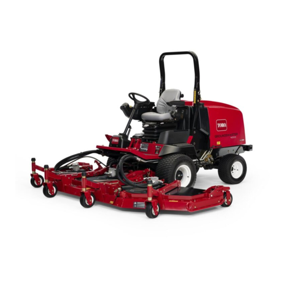
Toro 30411 Groundsmaster 4100-D Operator's Manual
Traction unit
Hide thumbs
Also See for 30411 Groundsmaster 4100-D:
- Service manual (340 pages) ,
- Operator's manual (22 pages) ,
- Installation instructions (4 pages)

Related Manuals for Toro 30411 Groundsmaster 4100-D


Summary of Contents for Toro 30411 Groundsmaster 4100-D
- Page 1 Form No. 3354-137 Rev D Groundsmaster® 4100-D Traction Unit Model No. 30411—Serial No. 2600000001 and Up Register your product at www.Toro.com Original Instructions (EN)
-
Page 2: Table Of Contents
Whenever you need service, genuine Toro parts, Engine ......28 or additional information, contact an Authorized Checking the Interlock Service Dealer or Toro Customer Service and have Switches ......29 the model and serial numbers of your product Pushing or Towing the ready. - Page 3 Battery Care ........43 Inspecting and Sharpening the Fuses..........43 Cutter Blade(s) ....56 Drive System Maintenance......43 Correcting Cutting Unit Changing the Planetary Gear Drive Mismatch ......57 Oil........43 Spark Arrestor Maintenance ...... 57 Changing the Rear Axle Servicing the Spark Arrestor Lubricant ......
-
Page 4: Safety
Safety ◊ inadequate braking; ◊ the type of machine is unsuitable for its This machine meets or exceeds CEN standard task; EN 836:1997, ISO standard 5395:1990, and ◊ lack of awareness of the effect of ANSI B71.4-1999 specifications in effect at the ground conditions, especially slopes;... - Page 5 • Evaluate the terrain to determine what • Never operate the machine with damaged accessories and attachments are needed to guards, shields, or without safety protective properly and safely perform the job. Only use devices in place. Be sure all interlocks are accessories and attachments approved by the attached, adjusted properly, and functioning manufacturer.
-
Page 6: Toro Mower Safety
The following list contains safety information an open flame or spark. specific to Toro products or other safety • Allow the engine to cool before storing in any information that you must know that is not included in the CEN, ISO, or ANSI standards. -
Page 7: Maintenance And Storage
• Do not operate the machine while wearing turn over if a wheel goes over the edge of a tennis shoes or sneakers. cliff or ditch, or if an edge caves in. • Wearing safety shoes and long pants is advisable •... -
Page 8: Sound Pressure Level
EN 11094. • If major repairs are ever needed or if assistance is desired, contact an Authorized Toro Vibration Level Distributor. • To make sure of optimum performance and Hand-Arm continued safety certification of the machine,... - Page 9 100-5622 100-5623 1. Height of cut adjustment 1. Low height of cut 2. High height of cut adjustment adjustment 100-5624 100-5623 1. Height of cut adjustment 1. Low height of cut 2. High height of cut adjustment adjustment 100-5693 100-5694 1.
- Page 10 104-2277 104-2277 1. To lock the parking brake, 4. Read the Operator’s 104-3599 latch the pedals together, Manual. apply the brake pedals, and 1. Do not step here. pull up on the knob. 2. Traction pedal 2. To unlock the parking 5.
- Page 11 104-8325 1. Lock/unlock the cutting unit service lock. 106-6752 1. Warning—read the Operator’s Manual. 2. Warning—lock the parking brake, stop the engine, and remove the ignition key before leaving the machine. 3. Warning—wear the seat belt when seated in the operator’s position.
- Page 12 Battery Symbols 106-6755 Some or all of these symbols are on your battery 1. Engine coolant under 3. Warning—do not touch the 1. Explosion hazard 6. Keep bystanders a safe pressure. hot surface. distance from the battery. 2. Explosion hazard—read the 4.
- Page 13 106-2046 1. Power Take-off (PTO) 6. Low 11. Silencer switch 16. Slow 2. Engage 7. Lock 12. Press the button 17. Continuous variable setting 3. Disengage 8. Flow divider 13. Key switch 18. Engine coolant temperature reset switch 4. Transmission 9.
-
Page 14: Setup
Setup Loose Parts Use the chart below to verify that all parts have been shipped. Step Description Qty. Seat kit (obtain separately) Seat suspension kit (obtain separately) Manual tube Install the seat, seat belt, and R-clamp manual tube. Seat belt Bolt Lock washer –... -
Page 15: Greasing The Machine
Step Greasing the Machine No Parts Required Procedure Before the machine is operated, it must be greased to ensure proper lubricating characteristics; refer to Greasing the Bearings and Bushings procedure of Lubrication, page 34. Failure to properly grease the machine will result in premature failure of critical parts. -
Page 16: Product Overview
Product Overview pedal. For no load, maximum ground speed, fully press the pedal while the throttle is in Fast. To stop, reduce your foot pressure on the traction pedal and allow it to return to the center position. Important: The speed limiter screw must stop the traction pedal before the pump reaches full stroke or damage to the pump may occur. -
Page 17: Key Switch
Glow Plug Indicator Light Key Switch When lit, the glow plug indicator light (Figure 2) The key switch (Figure 4) has three positions: Off, indicates that the glow plugs are on. On/Preheat, and Start. Engine Temperature Gauge PTO Switch This gauge (Figure 2) indicates the engine coolant The PTO switch (Figure 4) has three positions: On temperature. - Page 18 Specications Note: Specifications and design are subject to change without notice. go to www.Toro.com for a list of all approved Width of cut attachments and accessories. overall 124 inch (315 cm)
-
Page 19: Specifications
Note: When using different oil, drain all old temperatures) oil from the crankcase before adding new oil. Toro Premium Engine Oil is available from your distributor in either 15W-40 or 10W-30 viscosity. 5. Install the oil fill cap and dipstick. -
Page 20: Filling The Fuel Tank
Toro Premium All Season Hydraulic Fluid top of the tank, not the filler neck, with No. 2 (Available in 5 gallon pails or 55 gallon drums. See diesel fuel. Then install the cap. parts catalog or Toro distributor for part numbers.) - Page 21 SAE 85W-140 gear lube as a replacement. This is vegetable-oil based biodegradable oil tested and approved by Toro for this model. This fluid is The capacity of the system is approximately 16 oz not as resistant to high temperatures as standard (0.5 l).
- Page 22 before the engine is first started and every 400 hours thereafter. The capacity is 80 oz (2.4 l). Visually inspect for leaks daily. 1. Position the machine on a level surface. 2. Remove a check plug from one end of the axle (Figure 12) and make sure that the lubricant is up to the bottom of the hole.
-
Page 23: Checking The Tire Pressure
1. Start the engine and raise the cutting units so that the height-of-cut can be changed. Stop the engine and remove the key after the cutting unit is raised. 2. Position the castor wheel axles in the same holes in all castor forks. Refer to the following chart to determine the correct holes for the setting. - Page 24 inch spacers (refer to the chart below) onto the spindle shaft to get the desired height-of-cut; then slide the washer onto the shaft. Refer to the following chart to determine the combinations of spacers for the setting: Figure 17 Note: When using 1 inch (25 mm), 1-1/2 inch (38 mm), or occasionally 2 inch (51 mm) Figure 15 height-of-cut, move the skids and gage wheels...
- Page 25 height-of-cut bracket holes in the cutting unit frame (Figure 20 and Figure 21). 6. Insert the clevis pins and install the hairpin cotters. 7. Rotate tension rod counterclockwise (finger tight) to put tension on adjustment. Figure 20 1. Castor pivot arm 3.
-
Page 26: Adjusting The Blade
2. Rotate a center and adjoining wing blade so there blade tips are aligned. Measure distance between blade tips, distance should be approximately 0.38-0.62 inch (10-16 mm) (Figure 24). Figure 22 1. Skid Figure 24 Adjusting the Cutting Unit Rollers The cutting unit rollers should be mounted in 3. - Page 27 3. Check and adjust all castor tire pressures to 50 psi (345 kPa). 4. Check charge and counterbalance pressures with engine at high idle using test ports defined in Hydraulic Systems Test Ports. Adjust counterbalance setting to be 230 psi (1585 kPa) higher than charge pressure reading.
-
Page 28: Starting And Stopping The Engine
2. Move the throttle control to the mid-idle position. 3. Turn the ignition key to the Run position. The glow indicator will light. 4. When the glow indicator dims, turn the ignition key to the Start position. Release the key immediately when the engine starts and allow it to return to the Run position. -
Page 29: Checking The Interlock
Important: Allow engine to idle for 5 4. Sit on the seat, engage the parking brake and minutes before shutting it off after a full start the engine. Move the traction pedal out load operation. Failure to do so may lead to of the neutral position. -
Page 30: Pushing Or Towing The Machine
Pushing or Towing the Machine In an emergency, the machine can be moved forward by actuating the bypass valve in the variable displacement hydraulic pump and pushing or towing the machine. Do not push or tow the machine for more than 1/4 mile (0.4 km). Important: Do not push or tow the machine faster than 2-3 MPH (3-4.8 km/h) because internal transmission damage may occur. -
Page 31: Operating Tips
the transmission, engine speed, load on the cutting blades or other implement components, and the importance of the brakes. This product is designed to drive objects into the ground where they lose energy To maintain enough power for the traction unit quickly in grass areas. - Page 32 Select the Proper Height-of-Cut Setting to Suit Conditions Remove approximately 1 inch (25 mm) or no more than 1/3 of the grass blade when cutting. In exceptionally lush and dense grass, you may have to raise the height-of-cut to the next setting. Mow at Proper Intervals Under most normal conditions you will need to mow approximately every 4-5 days.
-
Page 33: Maintenance
Maintenance Note: Determine the left and right sides of the machine from the normal operating position. Recommended Maintenance Schedule(s) Maintenance Service Maintenance Procedure Interval • Torque the wheel lug nuts. After the rst 10 • Check the fan and alternator belt tension. operating hours •... -
Page 34: Premaintenance Procedures
If you leave the key in the ignition switch, someone could accidently start the engine and seriously injure you or other bystanders. Remove the key from the ignition before you do any maintenance. Premaintenance Procedures Service Interval Chart Figure 33 Lubrication are greased will rely upon regular maintenance to purge harmful debris from the bearing area. - Page 35 if damaged or worn. Bearings should operate smoothly with no detrimental characteristics such as high heat, noise, looseness or indications of corrosion (rust). Due to the operating conditions these bearing/seal packages are subject to (i.e. sand, turf chemicals, water, impacts, etc.) they are considered normal wear items.
- Page 36 • Lower link pivot (2) (Figure 38) • Latch pivot (2) (Figure 38) Note: Deck may have to be raised to expose the grease fittings for the lower link pivot and the latch pivot. • Castor fork shaft bushings (2) (Figure 39) •...
-
Page 37: Wing Cutting Units
Figure 43 Wing Cutting Units • Castor fork shaft bushing (1 each) (Figure 44) • Spindle shaft bearings (4) Figure 41 • Idler arm pivot bushings (1) (located on the idler arm) Figure 42 Wing Lift Assemblies Wing lift cylinder (4) (Figure 43) Figure 44... -
Page 38: Engine Maintenance
Engine Maintenance Air Cleaner Maintenance • Check the air cleaner body for damage which could cause an air leak. Replace if damaged. Check the whole intake system for leaks, damage or loose hose clamps. • Service the air cleaner filter only when the service indicator requires it or every 400 hours (more frequently in extremely dusty or dirty conditions). -
Page 39: Servicing The Engine Oil And Filter
the new filter by applying pressure to the outer rim of the element to seat it in the canister. Do not apply pressure to the flexible center of the filter. Important: Never attempt to clean the safety filter (Figure 47). Replace the safety filter with a new one after every three Figure 48 primary filter services. -
Page 40: Fuel System Maintenance
Fuel System Maintenance Servicing the Fuel System Under certain conditions, diesel fuel and fuel vapors are highly flammable and explosive. A fire or explosion from fuel can burn you and others and can cause property damage. • Use a funnel and fill the fuel tank outdoors, in an open area, when the Figure 50 engine is off and is cold. -
Page 41: Bleeding Air From The Injectors
Electrical System Maintenance Activating, Charging, and Connecting the Battery Warning CALIFORNIA Proposition 65 Warning Figure 51 Battery posts, terminals, and related accessories contain lead and lead 1. Fuel pre-lter compounds, chemicals known to the State of California to cause cancer and reproductive 3. - Page 42 8. Coat both battery connections with Grafo 6. Remove the filler caps. Slowly add electrolyte 112X (skin-over) grease, Toro Part No. 505-47, to each cell until the level is up to the fill ring. petroleum jelly, or light grease to prevent...
-
Page 43: Battery Care
Rinse with clear water. Gear Drive Oil Coat the battery posts and cable connectors with Grafo 112X (skin-over) grease (Toro Part No. Change the oil initially after first 200 hours of 505-47) or petroleum jelly to prevent corrosion. -
Page 44: Changing The Rear Axle
3. When all of the oil has drained, position the 3. Remove the check plugs to ease in draining of wheel so that the plug hole is at the ten or two the oil. o’clock position. 4. Remove the drain plugs and allow the oil to 4. -
Page 45: Checking The Rear Wheel
Checking the Rear Wheel Important: Cleaning the radiator or oil Toe-In cooler with water can promote premature corrosion and damage to components. After every 800 operating hours or annually, check the rear wheel toe-in. 1. Measure the center-to-center distance (at axle height) at the front and rear of the steering tires. -
Page 46: Belt Maintenance
Belt Maintenance Note: Make sure the belt is positioned on the spring side of the belt guide (Figure 64). Servicing the Alternator Belt Check the condition and tension of the belts (Figure 63) after every 100 operating hours. 1. Proper tension will allow 3/8 inch (10 mm) deflection when a force of 10 lb is applied on the belt midway between the pulleys. -
Page 47: Controls System Maintenance
Figure 66 1. Throttle cable Figure 65 Adjusting the Traction Pedal 1. Hydraulic motor 2. Mounting bolts Linkage 5. Remove the old belt from around the spindle The traction pedal should reach full stroke at the pulleys and idler pulley. same time it makes contact with the stop. -
Page 48: Hydraulic System Maintenance
filters after every 800 operating hours, in normal conditions. Fluid Use Toro replacement filters (Part No. 94-2621 Change the hydraulic fluid after every 800 for the left side of the machine and 75-1310 for operating hours, in normal conditions. If the fluid the right side of the machine). -
Page 49: Checking The Hydraulic Lines And Hoses
The test ports are used to test the pressure in Checking the Hydraulic the hydraulic circuits. Contact your local Toro Lines and Hoses distributor for assistance. Test Port A (Figure 71), located on the left side... - Page 50 Test Port E (Figure 75), located under the radiator, is used to measure the four-wheel drive pressure in reverse. Figure 72 1. Test port B Test Port C (Figure 73), located on the left side of Figure 75 the machine, is used to measure the left cutting 1.
-
Page 51: Adjusting The Cutting Unit Flow Control
Figure 79 1. Flow control valve Figure 77 1. Test port I 2. Test port H Mower Maintenance The counterbalance test port (Figure 78) is used to Pivoting (Tilting) the Front adjust the pressure in the counterbalance circuit. Cutting Unit Upright Recommended counterbalance pressure is 470 psi (3241 kPa). -
Page 52: Down
Cutting unit pitch is the difference in height-of-cut from the front of the blade plane to the back of the blade plane. Toro recommends a blade pitch of 1/4 inch (6 mm). That is the back of the blade plane is 1/4 inch (6 mm) higher than the front. -
Page 53: Servicing The Castor Arm
Figure 84 1. Castor arm tube 2. Bushings 5. Apply grease to the inside and outside of the new bushings. Using a hammer and flat plate, drive the bushings into the mounting tube. 6. Inspect the castor spindle for wear and replace it if it is damaged. -
Page 54: Replacing The Cutting Unit Hinge Covers
Figure 86 1. Castor wheel 3. Bearing 2. Castor pivot arm 4. Bearing spacer 2. Remove the bearing from the wheel hub and allow the bearing spacer to fall out (Figure 85 Figure 87 and Figure 86). Remove the bearing from the opposite side of the wheel hub. -
Page 55: Blade Maintenance
The blade must be replaced if a solid object is hit, the blade is out of balance, or if the blade is bent. Always use genuine Toro replacement blades to be sure of safety and optimum performance. Never use replacement blades made by other manufacturers because they could be dangerous. -
Page 56: Cutter Blade(S)
lever in the Off position, stop the engine, and remove the ignition key. 2. Examine the cutting ends of the blade carefully, especially where the flat and curved parts of the blade meet (Figure 93). Since sand and abrasive material can wear away the metal that connects the flat and curved parts of the blade, check the blade before using the mower. -
Page 57: Spark Arrestor Maintenance
5. Rotate the blades until the ends face forward and backward. Measure from the floor to the front tip of the cutting edge. Remember this If the blade is allowed to wear, a slot dimension. Then rotate the same blade so will form between the sail and flat part that the opposite end is forward, and measure of the blade (Figure 93). - Page 58 The muffler may be hot and could cause injury. Be careful while working around the muffler. 2. Start the engine. Plug the normal muffler exit with a block of wood or metal plate so that the exhaust flow will be forced out of the clean-out port.
-
Page 59: Storage
B. Clean the battery, terminals, and posts with a wire brush and baking soda solution. C. Coat the cable terminals and battery posts with Grafo 112X skin-over grease (Toro Part No. 505-47) or petroleum jelly to prevent corrosion. D. Slowly recharge the battery every 60 days for 24 hours to prevent lead sulfation of the battery. - Page 60 Schematics Electrical Schematic (Rev. A)
- Page 61 Hydraulic Schematic (Rev. A)
- Page 64 (Dealer) to obtain guarantee policies for your country, province, or state. If for any reason you are dissatised with your Distributor’s service or have difculty obtaining guarantee information, contact the Toro importer. If all other remedies fail, you may contact us at Toro Warranty Company.