Miller Spectrum 625 X-TREME Owner's Manual
Air plasma cutter
Hide thumbs
Also See for Spectrum 625 X-TREME:
- Owner's manual (44 pages) ,
- Owner's manual (40 pages) ,
- Owner's manual (40 pages)

Related Manuals for Miller Spectrum 625 X-TREME


Summary of Contents for Miller Spectrum 625 X-TREME
- Page 1 OM-264 267C 2014−09 Processes Air Plasma Cutting and Gouging Description Air Plasma Cutter Spectrum 625 X-TREME And XT40 Torch File: Plasma Cutters Visit our website at www.MillerWelds.com...
- Page 2 We know you don’t have time to do it any other way. That’s why when Niels Miller first started building arc welders in 1929, he made sure his products offered long-lasting value and superior quality.
-
Page 3: Table Of Contents
TABLE OF CONTENTS SECTION 1 − SAFETY PRECAUTIONS - READ BEFORE USING ....... . . 1-1. - Page 4 TABLE OF CONTENTS 8-2. Wrapper Removal ..............8-3.
-
Page 5: Section 1 − Safety Precautions - Read Before Using
SECTION 1 − SAFETY PRECAUTIONS - READ BEFORE USING pom_2013−09 Protect yourself and others from injury — read, follow, and save these important safety precautions and operating instructions. 1-1. Symbol Usage DANGER! − Indicates a hazardous situation which, if Indicates special instructions. not avoided, will result in death or serious injury. -
Page 6: Electric Shock Can Kill
FUMES AND GASES can be hazardous ELECTRIC SHOCK can kill. SIGNIFICANT DC VOLTAGE exists in Cutting produces fumes and gases. Breathing inverter power sources AFTER the re- these fumes and gases can be hazardous to your health. moval of input power. Keep your head out of the fumes. -
Page 7: Additional Symbols For Installation, Operation, And Maintenance
1-3. Additional Symbols For Installation, Operation, And Maintenance HOT PARTS can burn. BATTERY EXPLOSION can injure. D Do not touch hot parts bare handed. D Do not use plasma cutter to charge batteries or jump start vehicles unless it has a battery char- D Allow cooling period before working on ging feature designed for this purpose. -
Page 8: California Proposition 65 Warnings
1-4. California Proposition 65 Warnings Welding or cutting equipment produces fumes or gases This product contains chemicals, including lead, known to which contain chemicals known to the State of California to the state of California to cause cancer, birth defects, or other cause birth defects and, in some cases, cancer. -
Page 9: Section 2 − Consignes De Sécurité − Lire Avant Utilisation
SECTION 2 − CONSIGNES DE SÉCURITÉ − LIRE AVANT UTILISATION pom_2013−09fre Pour écarter les risques de blessure pour vous−même et pour autrui — lire, appliquer et ranger en lieu sûr ces consignes relatives aux précautions de sécurité et au mode opératoire. 2-1. - Page 10 D Coupez l’alimentation d’entrée avant d’installer l’appareil ou ÉTINCELLES PROJETÉES d’effectuer l’entretien. Verrouillez ou étiquetez la sortie peuvent provoquer des blessures. d’alimentation selon la norme OSHA 29 CFR 1910.147 (reportez−vous aux Principales normes de sécurité). Le coupage plasma produit des étincelles et projections de métal à...
-
Page 11: Dangers Supplémentaires En Relation Avec L'installation, Le Fonctionnement Et La Maintenance
D Si vous êtes à l’intérieur au moment du coupage, ventilez la pièce D Ne pointez pas le chalumeau en direction de votre corps ni de la ou ayez recours à une ventilation aspirante installée près de l’arc pièce à couper lorsque vous appuyez sur la gâchette − l’arc pilote pour évacuer les vapeurs et les gaz. - Page 12 D Tenir l’équipement (câbles et cordons) à distance des véhicules LIRE LES INSTRUCTIONS. mobiles lors de toute opération en hauteur. D Suivre les consignes du Manuel des applications pour l’équation D Lire et appliquer les instructions sur les de levage NIOSH révisée (Publication Nº94–110) lors du levage étiquettes et Mode d’emploi...
-
Page 13: Proposition Californienne 65 Avertissements
2-4. Proposition californienne 65 Avertissements Les équipements de soudage et de coupage produisent des Ce produit contient des éléments chimiques, dont le plomb, fumées et des gaz qui contiennent des produits chimiques reconnus par l’État de Californie pour leur caractère dont l’État de Californie reconnaît qu’ils provoquent des cancérogène ainsi que provoquant des malformations malformations congénitales et, dans certains cas, des... -
Page 14: Section 3 − Definitions
SECTION 3 − DEFINITIONS 3-1. Additional Safety Symbols And Definitions Some symbols are found only on CE products. Warning! Watch Out! There are possible hazards as shown by the symbols. Safe1 2012−05 When power is applied failed parts can explode or cause other parts to explode. Safe26 2012−05 3-2. -
Page 15: Section 4 − Specifications
A complete Parts List is available at www.MillerWelds.com SECTION 4 − SPECIFICATIONS 4-1. Serial Number And Rating Label Location The serial number and rating information for this product is located on the bottom. Use rating label to determine input power requirements and/or rated output. -
Page 16: Torch Dimensions And Weight
Use only compressed air which is free from dirt, oil, and water. Ensure that the connections are properly assigned and tightened. For torch replacement, see Miller torch manual Part No. OM-254449 Ensure correct air pressure (flow pressure) and airflow (volume) are set. Insufficient airflow can lead to the torch overheating. -
Page 17: Duty Cycle And Overheating
A complete Parts List is available at www.MillerWelds.com 4-4. Duty Cycle And Overheating Duty Cycle is percentage of 10 20% duty cycle minutes that unit can cut at rated load without overheating. If unit overheats, thermostat(s) opens, output stops, Temperature trouble light goes On, and cooling fan runs. -
Page 18: Section 5 − Installation
A complete Parts List is available at www.MillerWelds.com SECTION 5 − INSTALLATION 5-1. Selecting A Location Line Disconnect Device Locate unit near correct input power supply. Locate unit at least 18 in. (460 mm) Do not move or operate away from a wall or other unit where it could tip. -
Page 19: Connecting And Disconnecting Torch
A complete Parts List is available at www.MillerWelds.com 5-3. Connecting And Disconnecting Torch Turn off power source and disconnect input power. Torch Connector Quick Connect Collar Receptacle To connect torch: Align torch connector key with receptacle keyway, and insert into receptacle. -
Page 20: Connecting Work Clamp
A complete Parts List is available at www.MillerWelds.com 5-5. Connecting Work Clamp Work Clamp Workpiece Connect work clamp to a clean, paint-free location on workpiece, as close to cutting area as possible. Ref. 803 640-A 5-6. Electrical Service Guide Elec Serv 2014−01 Failure to follow these electrical service guide recommendations could create an electric shock or fire hazard. -
Page 21: Multi−Voltage Plug Adapter (Mvp) Connection
A complete Parts List is available at www.MillerWelds.com 5-8. Multi−Voltage Plug Adapter (MVP) Connection Selecting Plug Adapter Do not cut off power cord connector and rewire. The power cord connector and plugs adapters will work with standard NEMA receptacles. Modifying power cord, connector, and plug adapter... -
Page 22: Connecting 120 Volt Input Power
A complete Parts List is available at www.MillerWelds.com 5-9. Connecting 120 Volt Input Power Installation must meet all National and Local Codes − have only qualified persons make this installation. Special installation may be required where gasoline or volatile liquids are present −... - Page 23 A complete Parts List is available at www.MillerWelds.com Notes OM-264 267 Page 19...
-
Page 24: Connecting 1-Phase Input Power For 240 Vac
A complete Parts List is available at www.MillerWelds.com 5-10. Connecting 1-Phase Input Power For 240 VAC =GND/PE Earth Ground 240 VAC, 1 Tools Needed: Input10 2014−09 − 803 766-B / Ref. 254 665-A / Ref. 251 808-A OM-264 267 Page 20... - Page 25 A complete Parts List is available at www.MillerWelds.com 5-10. Connecting 1-Phase Input Power For 240 VAC (Continued) See rating label on unit and check input volt- Connect input conductors L1 and L2 to dis- Installation must meet all National and age available at site.
-
Page 26: Section 6 − Operation
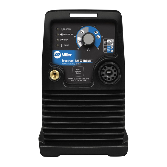
A complete Parts List is available at www.MillerWelds.com SECTION 6 − OPERATION 6-1. Controls A. Standard Front Panel Controls POWER PRESSURE 120V 120V TEMP 40 240V Ref. 253 015-A / Ref. 264 954-B / Ref. 805 326-A Output Control Power Light Power Switch Use control to set cutting output. - Page 27 A complete Parts List is available at www.MillerWelds.com B. Automation Front Panel Controls POWER PRESSURE 120V 120V TEMP 40 240V Ref. 253 015-A / Ref. 264 954-B / Ref. 805 326-A Output Control Trouble Lights (See Section 8-6) Power Switch Use control to set cutting output.
-
Page 28: Cutting Speed
A complete Parts List is available at www.MillerWelds.com 6-2. Cutting Speed Mild Steel Material Thickness Recommended Cut Speeds Arc Current Inches mm/min 22ga (0.03) 0.79 11,704 18ga (0.05) 1.22 7.701 16ga (0.06) 1.52 7,092 14ga (0.08) 2.01 5,100 22ga (0.03) 0.79 20,889 18ga (0.05) -
Page 29: Trigger Safety Lock
A complete Parts List is available at www.MillerWelds.com 6-3. Trigger Safety Lock Trigger Trigger Locked Trigger Unlocked Ref. 253 554-A 6-4. Plasma Cutting System Practices The pilot arc starts immediately when trigger is pressed. Always connect work clamp to a clean, DO NOT start pilot arc without cutting or paint-free location on workpiece, as close to gouging as this shortens the service life... -
Page 30: Sequence Of Cutting Operation
A complete Parts List is available at www.MillerWelds.com 6-5. Sequence Of Cutting Operation ° Connect work clamp to a clean, paint-free For standard (shielded) cutting, place drag shield on edge location on workpiece, as close to cutting of metal. For extended (non-shielded) cutting, use 1/8 in. area as possible. -
Page 31: Sequence Of Gouging Operation
A complete Parts List is available at www.MillerWelds.com 6-6. Sequence Of Gouging Operation Trigger pilot arc once before starting to gouge. Connect work clamp to a clean, paint-free location on workpiece, as close to cutting area as possible. The pilot arc starts immediately when trigger is pressed. -
Page 32: Sequence Of Piercing Operation
A complete Parts List is available at www.MillerWelds.com 6-7. Sequence Of Piercing Operation The pilot arc starts immediately when trigger is pressed. ° Connect work clamp to a clean, paint-free Hold torch at approximately 45° location on workpiece, as close to cutting to the workpiece. -
Page 33: Section 7 − Mechanized Operation
A complete Parts List is available at www.MillerWelds.com SECTION 7 − MECHANIZED OPERATION 7-1. XT40M Mounting Position XT40M Machine Torch Square Use a square to align torch perpen- dicular to the work surface. 90° 7-2. Remote Control Receptacle Remote trigger will only operate with a machine torch... -
Page 34: Remote Control Cable Connection
A complete Parts List is available at www.MillerWelds.com 7-4. Remote Control Cable Connection Turn off power source. Remote Control Cable Plug Remote Control Receptacle Connect plug to receptacle on unit front panel. Blue Blue/White Remote Start* Orange Orange/White Okay To Move Relay Contacts: 3 amps/28 VDC or 3 amps/120 VAC Brown... -
Page 35: Section 8 − Maintenance & Troubleshooting
A complete Parts List is available at www.MillerWelds.com SECTION 8 − MAINTENANCE & TROUBLESHOOTING 8-1. Routine Maintenance Maintain more often Disconnect power during severe conditions. before maintaining. n = Check Z = Change ~ = Clean l = Replace Reference * To be done by Factory Authorized Service Agent Each Section 4-2,... -
Page 36: Checking Or Replacing Filter Element
A complete Parts List is available at www.MillerWelds.com 8-3. Checking Or Replacing Filter Element Tools Needed: Torx 25 Ref. 805 327-A / Ref. 264 954-B Filter Base Check filter element for dirt and moisture, Turn power Off, and disconnect in- and replace if necessary. -
Page 37: Checking/Replacing Retaining Cup, Tip, And Electrode
A complete Parts List is available at www.MillerWelds.com 8-5. Checking/Replacing Retaining Cup, Tip, And Electrode Overtightening will strip threads. Do not overtighten retaining cup during assembly. Do not cross-thread parts causing stripping. Use care during torch assembly and parts replacement. Inspect shield cup, tip, and electrode for wear before cutting or whenever cutting speed has been signifi- cantly reduced. -
Page 38: Status/Trouble Lights
A complete Parts List is available at www.MillerWelds.com 8-6. Status/Trouble Lights Difficulty establishing a pilot arc may indicate consumables need to be cleaned or replaced. Light Condition Status/Possible Cause Power Input power is okay. When Power light is on, system is normal if these lights Pressure/Cup/T emp are off. -
Page 39: Troubleshooting Power Source
A complete Parts List is available at www.MillerWelds.com 8-7. Troubleshooting Power Source Trouble Remedy No pilot arc; difficulty in establishing an Clean or replace worn consumables as necessary (see torch Owner’s Manual). arc. Check for damaged torch or torch cable (see torch Owner’s Manual). No cutting output;... -
Page 40: Section 9 − Electrical Diagram
SECTION 9 − ELECTRICAL DIAGRAM Figure 9-1. Circuit Diagram For Spectrum 625 X-TREME OM-264 267 Page 36... - Page 41 264 143-A OM-264 267 Page 37...
- Page 42 Figure 9-2. Circuit Diagram For Spectrum 625 X-TREME CNC OM-264 267 Page 38...
- Page 43 265 480-A OM-264 267 Page 39...
-
Page 44: Section 10 − Parts List
SECTION 10 − PARTS LIST 10-1. Recommended Spare Parts Item Dia. Part Mkgs. Description Quantity Recommended Spare Parts ....253008 Cord Set, 250V 6-30P 10ga 3/C 12 ft St Jkt Locking . - Page 45 Item Part Description 249 970 Torch Handle Kit (1) 249 971 Torch Trigger ....Microswitch (1) 260 637 Leads, XT40 12ft Hand Held Torch w/Disconnect (1) 260 638 Leads, XT40 20ft Hand Held Torch w/Disconnect (1)
- Page 46 See Figure 10-1 for Item Part additional consumable parts. Description 259 363 Mounting Screw (3) 259 361 Mounting Sleeve (1) 259 333 Kit, Torch Body W/Switch (1) 263 389 Positioning Sleeve Short Body (1) 259 357 Positioning Sleeve Long Body (1) 259 359 Strain Relief (1) 259 330...
- Page 47 See Figure 10-1 for Item Part additional consumable parts. Description 249 930 30 Amp Drag Shield (1) 249 937 40 Amp Machine Shield (1) 263 310 XT-Mach Torch, Shield Sense Terminal w/Instruction (1) 249 932 30/40 Amp Retaining Cup (1) 249 927 30 Amp Tip (1) 249 928...
- Page 48 Notes...
- Page 49 Notes MATERIAL THICKNESS REFERENCE CHART 24 Gauge (.025 in.) 22 Gauge (.031 in.) 20 Gauge (.037 in.) 18 Gauge (.050 in.) 16 Gauge (.063 in.) 14 Gauge (.078 in.) 1/8 in. (.125 in.) 3/16 in. (.188 in.) 1/4 in. (.25 in.) 5/16 in.
- Page 50 Notes Work like a Pro! Pros weld and cut safely. Read the safety rules at the beginning of this manual.
- Page 51 Effective January 1, 2014 (Equipment with a serial number preface of ME or newer) This limited warranty supersedes all previous Miller warranties and is exclusive with no other guarantees or warranties expressed or implied. Warranty Questions? LIMITED WARRANTY − Subject to the terms and conditions below, 6 Months —...
- Page 52 Contact the Delivering Carrier to: File a claim for loss or damage during shipment. For assistance in filing or settling claims, contact your distributor and/or equipment manufacturer’s Transportation Department. © ORIGINAL INSTRUCTIONS − PRINTED IN USA 2014 Miller Electric Mfg. Co. 2014−01...
Need help?
Do you have a question about the Spectrum 625 X-TREME and is the answer not in the manual?
Questions and answers