Miller Spectrum 625 Owner's Manual
Hide thumbs
Also See for Spectrum 625:
- Owner's manual (44 pages) ,
- Owner's manual (40 pages) ,
- Owner's manual (52 pages)

Related Manuals for Miller Spectrum 625


Summary of Contents for Miller Spectrum 625
- Page 1 OM-2239 207 542J August 2005 Processes Air Plasma Cutting and Gouging Description Air Plasma Cutter Spectrum 625 And ICE-40C Torch Visit our website at www.MillerWelds.com...
- Page 2 We know you don’t have time to do it any other way. That’s why when Niels Miller first started building arc welders in 1929, he made sure his products offered long-lasting value and superior quality.
-
Page 3: Table Of Contents
TABLE OF CONTENTS SECTION 1 − SAFETY PRECAUTIONS - READ BEFORE USING ........1-1. -
Page 5: Section 1 − Safety Precautions - Read Before Using
SECTION 1 − SAFETY PRECAUTIONS - READ BEFORE USING pom _4/05 Y Warning: Protect yourself and others from injury — read and follow these precautions. 1-1. Symbol Usage Means Warning! Watch Out! There are possible hazards with this procedure! The possible hazards are shown in the adjoining symbols. - Page 6 If ventilation is poor, wear an approved air-supplied respirator. EXPLODING PARTS can injure. Read and understand the Material Safety Data Sheets (MSDSs) and the manufacturer’s instruction for metals to be cut, coatings, D On inverter power sources, failed parts can ex- and cleaners.
-
Page 7: Additional Symbols For Installation, Operation, And Maintenance
D Use proper static-proof bags and boxes to store, move, or ship PC boards. D Read Owner’s Manual before using or servic- ing unit. D Use only genuine Miller/Hobart replacement H.F. RADIATION can cause interference. parts. D High frequency (H.F.) can interfere with radio FLYING METAL can injure eyes. -
Page 8: Principal Safety Standards
1-5. Principal Safety Standards Safety in Welding, Cutting, and Allied Processes, ANSI Standard Z49.1, Code for Safety in Welding and Cutting, CSA Standard W117.2, from from Global Engineering Documents (phone: 1-877-413-5184, website: Canadian Standards Association, Standards Sales, 178 Rexdale Bou- www.global.ihs.com). -
Page 9: Section 2 − Consignes De Sécurité − Lire Avant Utilisation
SECTION 2 − CONSIGNES DE SÉCURITÉ − LIRE AVANT UTILISATION pom_fre 4/05 Y Avertissement : se protéger et protéger les autres contre le risque de blessure — lire et respecter ces consignes. 2-1. Signification des symboles Signifie Mise en garde ! Soyez vigilant ! Cette procédure présente des risques de danger ! Ceux-ci sont identifiés par des symboles adjacents aux directives. - Page 10 N’approchez pas le tube du chalumeau et l’arc pilote lorsque la gâ- LE BRUIT peut endommager l’ouïe. chette est enfoncée. Le câble de masse doit être pincé correctement sur la pièce à cou- Certaines applications de coupage produisent un bruit per, métal contre métal (et non de telle sorte qu’il puisse se constant, ce qui peut endommager l’ouïe si le niveau détacher), ou sur la table de travail le plus près possible de la ligne...
-
Page 11: Dangers Supplémentaires En Relation Avec L'installation, Le Fonctionnement Et La Maintenance
D Les bouteilles ne doivent pas être près de la zone de coupage ni de D Détournez votre visage du détendeur−régulateur lorsque vous ouvrez tout autre circuit électrique. la soupape de la bouteille. D Un contact électrique ne doit jamais se produire entre un chalumeau D Le couvercle du détendeur doit toujours être en place, sauf lorsque de plasma d’arc et une bouteille. -
Page 12: Principales Normes De Sécurité
D Veiller à couper à une distance de 100 mètres de tout équipement LE COUPAGE Ã L’ARC peut causer électronique sensible. des interférence. D S’assurer que la source de coupage est correctement branchée et mise à la terre. D L’énergie électromagnétique peut gêner le fonction- D Si l’interférence persiste, l’utilisateur doit prendre des mesures sup- nement d’appareils électroniques comme des ordi- plémentaires comme écarter la machine, utiliser des câbles blindés... -
Page 13: Section 3 − Definitions
SECTION 3 − DEFINITIONS 3-1. Symbols And Definitions For Nameplate And Serial Number/Rating Label Plasma Arc Cutting Adjust Air/Gas Low Air Pressure Amperes (PAC) Pressure Light No − Do Not Do Volts Increase Temperature This Protective Earth Single Phase Constant Current Voltage Input (Ground) Percent... -
Page 14: Section 4 − Installation
SECTION 4 − INSTALLATION 4-1. Specifications Amperes Input Maximum at Rated Load Rated Rated Type of Plasma Flow/ Open- Output 50/60 50/60 Hz Cutting Circuit Output Output Pressure Capacity Capacity Voltage DC Voltage DC 208 V 230 V Direct 40 A @ 6 CFM Air Or 0.5 in... -
Page 15: Torch Dimensions And Weight
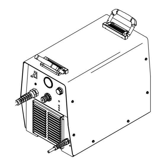
4-4. Torch Dimensions And Weight 8-3/8 in (213 mm) 1 in (25 mm) 3.5 lb (1.6 kg) With 25 ft (7.6 m) Cable 1-3/8 in (35 mm) Ref. 801 397-A 4-5. Unit Dimensions, Weight, And Movement 17-1/4 in (438 mm) Dimensions And Weight 57 lb (25.9 kg) 15-1/4 in... -
Page 16: Connecting Work Clamp And Gas/Air Supply
4-6. Connecting Work Clamp and Gas/Air Supply Work Clamp Workpiece Connect work clamp to a clean, paint-free location on workpiece, as close to cutting area as possible. Use only clean, dry air with 90 to 150 psi (620 to 1035 kPa) pressure. -
Page 17: Electrical Service Guide
4-7. Electrical Service Guide 50/60 Hz Single Phase Input Voltage Input Amperes At Rated Output Max Recommended Standard Fuse Rating In Amperes Cricuit Breaker , Time-Delay Normal Operating Min Input Conductor Size In AWG Max Recommended Input Conductor Length In Feet (Meters) (24) (30) Min Grounding Conductor Size In AWG... -
Page 18: Selecting A Location And Connecting Input Power
4-9. Selecting A Location And Connecting Input Power Plug (NEMA Type 6-50P) Receptacle (NEMA Type 6-50R) Connect plug to receptacle. Input And Grounding Conductors For single-phase operation: 18 in (457 mm) of Y Do not move or operate unit Y Make input power space for airflow... -
Page 19: Wiring Optional 240 Volt Plug (119 172) For Connection To Bobcat, Trailblazer Or Champion 10,000
4-10. Wiring Optional 240 Volt Plug (119 172) For Connection To Bobcat, Trailblazer Or Champion 10,000 Input And Grounding Conductors Plug Wired for 240 V, 2-Wire Load Neutral (Brass) Terminal And Tools Needed: Prong (Not Used) Load 1 (Brass)Terminal And Prong Load 2 (Brass) Terminal And Prong... -
Page 20: Installing Alternative Plug
4-11. Installing Alternative Plug This procedure is necessary if the unit is to be connected to a 208/230 VAC Supplied 230 VAC Plug receptacle that requires a plug that is different from the supplied plug. Cut cord close to plug. Alternative Plug (230 VAC Plug Shown) Input (Black Lead) -
Page 21: Section 5 − Operation
SECTION 5 − OPERATION 5-1. Controls Ref. 207 299 Output Control Power Switch At ambient temperatures below −55 C Use control to set cutting output. (235 readjustment gas/air The fan will normally run for pressure regulator may be necessary Place control in Gas/Air Set position to safely approximately 5 seconds after power (see Section 4-12). -
Page 22: Trigger Safety Lock
5-3. Trigger Safety Lock Trigger Trigger Locked Trigger Unlocked 801 397-A 5-4. Plasma Cutting System Practices The pilot arc starts immediately when trigger is pressed. Always connect work clamp to a clean, DO NOT start pilot arc without cutting or Set correct air pressure for process: paint-free location on workpiece, as close to gouging as this shortens the service life... -
Page 23: Sequence Of Cutting Operation
5-5. Sequence Of Cutting Operation Connect work clamp to a clean, paint-free Set air pressure to 75 PSI (517 kPa) for cutting. location on workpiece, as close to cutting area as possible. The pilot arc starts immediately when trigger is pressed. °... -
Page 24: Sequence Of Gouging Operation
5-6. Sequence Of Gouging Operation Connect work clamp to a clean, paint-free Set air pressure to 55 PSI (379 kPa) for gouging. location on workpiece, as close to cutting area as possible. The pilot arc starts immediately when trigger is pressed. Hold torch at approximately Raise trigger lock and press trigger. -
Page 25: Sequence Of Piercing Operation
5-7. Sequence Of Piercing Operation The pilot arc starts immediately when trigger is pressed. Connect work clamp to a clean, paint-free Set air pressure to 75 PSI Hold torch at an angle to the location on workpiece, as close to cutting workpiece. -
Page 26: Section 6 − Maintenance & Troubleshooting
SECTION 6 − MAINTENANCE & TROUBLESHOOTING 6-1. Routine Maintenance Maintain more often Y Disconnect power before maintaining. during severe conditions. Each Use Check Torch Check Gas/Air Tip, Electrode, Pressure And Shield Cup Every Week Check Shield Cup Shutdown System 3 Months Service Air Replace Filter/Regulator... -
Page 27: Overload Protection: Status Lights & Checking Shield Cup Shutdown System
6-2. Overload Protection: Status Lights & Checking Shield Cup Shutdown System If certain problems occur, a status light comes on, and output stops. Pressure Light Lights if gas/air pressure is below 40 PSI (276 kPa). Turn power Off, and check for proper gas/air pressure (see... -
Page 28: Checking/Replacing Retaining Cup, Tip, And Electrode
6-3. Checking/Replacing Retaining Cup, Tip, And Electrode Overtightening will strip threads. Do not overtighten retaining cup during assembly. Do not cross-thread parts causing stripping. Use care during torch assembly and parts replacement. Inspect shield cup, tip, and electrode for wear before cutting or whenever cutting speed has been significantly reduced. -
Page 29: Torch And Work Cable Replacement
6-4. Torch And Work Cable Replacement If torch or work cable needs to be removed Slide torch cable, connector, and plugs Slide work cable through nut and out of unit. or replaced, proceed as follows: through nut and out of unit. Retain nut for Retain nut for use on replacement strain use on replacement strain relief. -
Page 30: Troubleshooting Power Source
6-5. Troubleshooting Power Source Press torch trigger and check if pilot arc ignites. Check torch consumables. Does pilot arc *Check torch connections, Is Power switch ignite? Place Power switch in the air filter, pressure switch S3, S1 in the On On position. -
Page 31: Troubleshooting Torch
6-6. Troubleshooting Torch Torch travel speed too slow; increase travel speed (see Section 5-5). Clean Does arc go replace torch consumables Go to Section 6-5. as necessary (see Section while cutting? 6-3). Be sure work clamp is securely attached workpiece. Be sure work clamp is securely attached to work- piece. -
Page 32: Section 7 − Electrical Diagram
SECTION 7 − ELECTRICAL DIAGRAM 212 926-A Figure 7-1. Circuit Diagram OM-2239 Page 28... - Page 33 Notes OM-2239 Page 29...
-
Page 34: Section 8 − Parts List
SECTION 8 − PARTS LIST Hardware is common and not available unless listed. Ref. 803 223-C Figure 8-1. Main Assembly OM-2239 Page 30... - Page 35 207296 XFMR,MAIN SPECTRUM 625 ........
- Page 36 NOTE: The ICE-40C torch is specifically for use Item Part Description only with this plasma cutting unit. 195 110 ICE-40C 25ft Torch 195 111 ICE-40C 50ft Torch 183 427 Handle Assy, complete (1) 192 059 Main Body (1) 209 298 Leads, 25ft (1) 209 299 Leads, 50ft (1)
- Page 37 For extended tip use, set Amperage control to 35. Drag Shield Retaining Cup Electrode Swirl Ring O-Ring 204 323 192 050 204 325 192 047 169 232 192 049 Standard Cutting Apply silicone grease (169 231) before installing Electrode Deflector Retaining Cup 35A Tip 177 888...
- Page 38 Notes Work like a Pro! Pros weld and cut safely. Read the safety rules at the beginning of this manual.
- Page 39 Effective January 1, 2005 (Equipment with a serial number preface of “LF” or newer) This limited warranty supersedes all previous Miller warranties and is exclusive with no other Warranty Questions? guarantees or warranties expressed or implied. Call LIMITED WARRANTY − Subject to the terms and conditions Induction Heating Coils and Blankets below, Miller Electric Mfg.
-
Page 40: Options And Accessories
Contact the Delivering Carrier to: File a claim for loss or damage during shipment. For assistance in filing or settling claims, contact your distributor and/or equipment manufacturer’s Transportation Department. © PRINTED IN USA 2005 Miller Electric Mfg. Co. 1/05...
Need help?
Do you have a question about the Spectrum 625 and is the answer not in the manual?
Questions and answers