Table of Contents
Advertisement
Advertisement
Table of Contents
Troubleshooting

Related Manuals for Miller PRO 300


Summary of Contents for Miller PRO 300
- Page 1 OM-4422 215 177E July 2004 Processes Stick (SMAW) Welding TIG (GTAW) Welding MIG (GMAW) Welding Flux Cored (FCAW) Welding Air Carbon Arc (CAC-A) Cutting and Gouging Description Engine Driven Welding Generator PRO 300 (CAT-Powered) Visit our website at www.MillerWelds.com...
- Page 2 We know you don’t have time to do it any other way. That’s why when Niels Miller first started building arc welders in 1929, he made sure his products offered long-lasting value and superior quality.
-
Page 3: Table Of Contents
TABLE OF CONTENTS SECTION 1 − SAFETY PRECAUTIONS − READ BEFORE USING ........1-1. - Page 4 TABLE OF CONTENTS SECTION 8 − MAINTENANCE & TROUBLESHOOTING ......... . . 8-1.
-
Page 5: Section 1 − Safety Precautions − Read Before Using
SECTION 1 − SAFETY PRECAUTIONS − READ BEFORE USING rom _nd_8/03 Y Warning: Protect yourself and others from injury — read and follow these precautions. 1-1. Symbol Usage Means Warning! Watch Out! There are possible hazards with this procedure! The possible hazards are shown in the adjoining symbols. -
Page 6: Engine Hazards
WELDING can cause fire or explosion. HOT PARTS can cause severe burns. D Allow cooling period before maintaining. Welding on closed containers, such as tanks, drums, or D Wear protective gloves and clothing when working on pipes, can cause them to blow up. Sparks can fly off from the welding arc. -
Page 7: Compressed Air Hazards
STEAM AND HOT COOLANT can burn. BATTERY ACID can BURN SKIN and EYES. D Do not tip battery. D If possible, check coolant level when engine is cold to avoid scalding. D Replace damaged battery. D Always check coolant level at overflow tank, if pres- D Flush eyes and skin immediately with water. -
Page 8: California Proposition 65 Warnings
READ INSTRUCTIONS. ARC WELDING can cause interference. D Use only genuine MILLER/Hobart replacement D Electromagnetic energy can interfere with sensitive parts. electronic equipment such as microprocessors, computers, and computer-driven equipment such as D Perform engine and air compressor (if applicable) robots. -
Page 9: Section 2 − Consignes De Sécurité − Lire Avant Utilisation
SECTION 2 − CONSIGNES DE SÉCURITÉ − LIRE AVANT UTILISATION rom_fre 8/03 Y Avertissement: Protégez vous et les autres des blessures − lisez et suivez ces précautions. 2-1. Signification des symboles Signifie Mise en garde ! Soyez vigilant ! Cette procédure Ce groupe de symboles si- présente des risques de danger ! Ceux-ci sont identifiés par gnifie Mise en garde ! -
Page 10: Dangers Existant En Relation Avec Le Moteur
Suivre les recommandations dans OSHA 1910.252(a)(2)(iv) et NFPA 51B LES ACCUMULATIONS DE GAZ ris- pour les travaux à chaud et avoir de la surveillance et un extincteur à proxi- quent de provoquer des blessures ou mité. même la mort. DES PARTICULES VOLANTES peuvent blesser les yeux. -
Page 11: Dangers Liés À L'air Comprimé
D Pour empêcher tout démarrage accidentel pendant les travaux d’entretien, L’EXPLOSION DE LA BATTERIE peut débrancher le câble négatif (−) de batterie de la borne. RENDRE AVEUGLE. D Ne pas approcher les mains, cheveux, vêtements lâches et outils des orga- nes mobiles. -
Page 12: Principales Normes De Sécurité
LE SURCHAUFFEMENT peut endom- LIRE LES INSTRUCTIONS. mager le moteur électrique. D Utiliser seulement les pièces de rechange d’origine. D Effectuer la maintenance du moteur et du compres- D Arrêter ou déconnecter l’équipement avant de dé- seur (si applicable) suivant ce manuel et le manuel du marrer ou d’arrêter le moteur. -
Page 13: Section 3 − Definitions
SECTION 3 − DEFINITIONS 3-1. Warning Label Definitions Warning! Watch Out! There are possible hazards as shown by the symbols. Do not smoke and keep matches and flames away from battery. Sparks can cause battery gases to explode. Battery explosion can blind and injure. Wear a face shield. - Page 14 Warning! Watch Out! There are possible hazards as shown by the symbols. Hot muffler and exhaust pipes can cause severe burns. Do not touch hot muffler or pipes. S-176 230 3/96 3/96 Warning! Watch Out! There are possible hazards as shown by the symbols.
- Page 15 Warning! Watch Out! There are possible hazards as shown by the symbols. Fire hazard from leaking engine fuel. Fire can result from welding base non-designated areas causing a possible fuel leak. Fuel tank is located inside base. Do not weld on base of unit. Weld only on supplied brackets or bolt unit down.
- Page 16 Remove unit from shipping S-177 571 crate. Remove Owner’s Manual from unit. Follow instructions to install muffler. Read Owner’s Manual. Read labels on unit. Use Diesel Fuel only, and fill fuel tank. Leave room for expansion. Warning! Watch Out! There are possible hazards as shown by the symbols.
-
Page 17: Manufacturer's Rating Label
3-2. Manufacturer’s Rating Label Ref. 216 347-B OM-4422 Page 13... -
Page 18: Symbols And Definitions
3-3. Symbols And Definitions NOTE Some symbols are found only on CE products. Fast (Run, Weld/ Stop Engine Slow (Idle) Start Engine Power) Starting Aid Engine Oil Battery (Engine) Engine Oil (Preheat) Pressure Check Injectors/ Check Valve Protective Earth Fuel Pump Clearance (Ground) -
Page 19: Section 4 − Specifications
SECTION 4 − SPECIFICATIONS 4-1. Weld, Power, And Engine Specifications Maximum Welding Weld Output Rated Welding Open- Generator Power Fuel Engine Mode Range Output Circuit Rating Capacity Voltage 400 A, 23 Volts DC, 40% Duty Cycle 20 − 410 A 410 A 300 A, 32 Volts DC 300 A, 32 Volts DC... -
Page 20: Volt-Ampere Curves
4-3. Volt-Ampere Curves A. Stick Mode The volt-ampere curves show the minimum and maximum voltage and amperage output capabilities of the welding generator. Curves of all other settings fall between the curves shown. DC AMPERES B. MIG Mode DC AMPERES C. -
Page 21: Fuel Consumption
4-4. Fuel Consumption The curve shows typical fuel use under weld or power loads. 2.00 1.75 1.50 1.25 1.00 0.75 0.50 0.25 IDLE 0.00 DC WELD AMPERES AT 100% DUTY CYCLE 217 509 4-5. Duty Cycle And Overheating Duty Cycle is percentage of 10 min- 100% Duty Cycle At 250 Amperes utes that unit can weld at rated load without overheating. -
Page 22: Ac Generator Power Curve
4-6. AC Generator Power Curve The ac power curve shows the gen- erator power in amperes available at the 120 and 240 volt receptacles. AC AMPERES IN 240 V MODE AC AMPERES IN 120 V MODE 217 519 Notes MATERIAL THICKNESS REFERENCE CHART 24 Gauge (.025 in) 22 Gauge (.031 in) 20 Gauge (.037 in) -
Page 23: Section 5 − Installation
SECTION 5 − INSTALLATION 5-1. Installing Welding Generator Y Always securely fasten weld- ing generator onto transport vehicle or trailer and comply with all DOT and other applica- Movement ble codes. Y Always ground generator frame to vehicle frame to pre- vent electric shock and static electricity hazards. -
Page 24: Mounting Welding Generator
5-2. Mounting Welding Generator Y Do not weld on base. Weld- ing on base can cause fuel tank fire or explosion. Weld only on the four mounting brackets or bolt unit down. Supporting The Unit Y Do not mount unit by sup- porting the base only at the four mounting brackets. -
Page 25: Installing Exhaust Pipe
5-3. Installing Exhaust Pipe Y Stop engine and let cool. Point exhaust pipe in desired di- rection but always away from front panel and direction of travel. Tools Needed: 1/2 in 803 582 / Ref. 214 778-B Notes Work like a Pro! Pros weld and cut safely. -
Page 26: Activating The Dry Charge Battery (If Applicable)
5-4. Activating The Dry Charge Battery (If Applicable) Remove battery from unit. Eye Protection − Safety Glasses Or Face Shield Rubber Gloves Vent Caps Sulfuric Acid Electrolyte (1.265 Specific Gravity) Well Fill each cell with electrolyte to bottom of well (maximum). Y Do not overfill battery cells. -
Page 27: Connecting The Battery
5-5. Connecting The Battery Close door after connecting battery. Tools Needed: 1/2 in Y Connect Negative (−) Cable Last. − 803 563 / Ref. 214 778-B / S-0756-C Notes OM-4422 Page 23... -
Page 28: Engine Prestart Checks
5-6. Engine Prestart Checks Check radiator coolant level when fluid is low in recovery tank. Full Full Diesel Capacity: 6 qt (5.7 L) Coolant Recovery Tank Hot Full Cold Full Full 803 563 Do not run out of fuel or air will enter fuel sys- freeze to mixture if using the unit in tempera- Check all engine fluids daily. -
Page 29: Connecting To Weld Output Terminals
5-7. Connecting To Weld Output Terminals Y Stop engine. Work (−) Weld Output Terminal CV (Wire) Weld Output Terminal CC (Stick/TIG) Weld Output Terminal Stick and TIG Welding For Stick and TIG welding Direct Current Elec- trode Positive (DCEP), connect electrode holder cable to CC (Stick/TIG) terminal on right and work cable to Negative (−) terminal on left. -
Page 30: Connecting To Remote 14 Receptacle Rc14
5-9. Connecting To Remote 14 Receptacle RC14 Socket* Socket Information 24 volts ac. Protected by circuit breaker CB8. 24 VOLTS AC 24 VOLTS AC Contact closure to A completes 24 volt ac contactor control circuit. Output to remote control:+10 volts dc in MIG mode; 0 to +10 volts dc in Stick or TIG mode. - Page 31 Notes Start Your Professional Over 80,000 trained 400 Trade Square East, Troy, Ohio 45373 Welding Career Now! since 1930! 1-800-332-9448 www.welding.org OM-4422 Page 27...
-
Page 32: Section 6 − Operating Welding Generator
SECTION 6 − OPERATING WELDING GENERATOR 6-1. Front Panel Controls (See Section 6-2) 214 778-B / 803 563 OM-4422 Page 28... -
Page 33: Description Of Front Panel Controls (See Section 6-1)
6-2. Description Of Front Panel Controls (See Section 6-1) Engine Starting Controls Engine Gauges, Meters, And Lights Process/Contactor Switch Fuel Gauge/Hourmeter Preheat Switch See Section 6-3 for Process/Contactor switch information. Use gauge to check fuel level or total engine Use switch to energize starting aid for cold operating hours. -
Page 34: Process/Contactor Switch On Cc/Cv Models
6-3. Process/Contactor Switch On CC/CV Models Process/Contactor Switch Y Weld output terminals are ener- gized when Process/Contactor switch is in a Weld Terminals Al- ways On position and the engine is running. Use switch to select weld process and weld output on/off control (see table be- low). -
Page 35: Lift-Arce Start Procedure
6-4. Lift-Arc Start Procedure Lift-Arc t TIG With Lift-Arct TIG selected, start arc as follows: TIG Electrode Workpiece Lift-Arc Start Method Turn gas on. Touch tungsten electrode to workpiece at weld start point. Hold electrode workpiece for 1-2 seconds, and slowly lift electrode. -
Page 36: Remote Voltage/Amperage Control
6-5. Remote Voltage/Amperage Control Remote 14 Receptacle RC14 Connect optional remote control to RC14 (see Section 5-9). When a remote control is connected to the Remote receptacle, the Auto Sense Re- mote feature automatically switches volt- age/amperage control to the remote con- trol. -
Page 37: Section 7 − Operating Auxiliary Equipment
SECTION 7 − OPERATING AUXILIARY EQUIPMENT 7-1. 120 Volt And 240 Volt Receptacles 214 778-B 120 V 20 A AC (shown) CB5 opens, the receptacles do not work. At least once a month, run engine at Receptacle RC5 and/or GFCI1 Place CB5 switch in On position to reset cir- weld/power speed and press test but- cuit breaker. -
Page 38: Section 8 − Maintenance & Troubleshooting
SECTION 8 − MAINTENANCE & TROUBLESHOOTING 8-1. Routine Maintenance Note Follow the storage procedure in the engine owner’s manual if the unit will not be used for an extended period. Y Stop engine before maintaining. Recycle engine See Engine Manual and Maintenance fluids. -
Page 39: Caterpillar Customer Assistance
Every 500 h Replace primary (in-line) Replace Secondary fuel filter. See Section (Canister) Fuel Filter. 8-9. See Section 8-9. Repair Or Replace Damaged Cables. Every 1000 h Check Radiator Drain Sludge FUEL Fluid Level. See From Fuel Section 5-6. SLUDGE Tank. -
Page 40: Maintenance Label
8-3. Maintenance Label OM-4422 Page 36... -
Page 41: Servicing Air Cleaner
8-4. Servicing Air Cleaner Y Stop engine. Y Do not run engine without air cleaner or with dirty element. En- gine damage caused by using a damaged element is not covered by the warranty. The air cleaner primary element can be cleaned but the dirt holding capac- ity of the filter is reduced with each cleaning. -
Page 42: Inspecting And Cleaning Optional Spark Arrestor Muffler
8-5. Inspecting And Cleaning Optional Spark Arrestor Muffler Y Stop engine and let cool. Spark Arrestor Muffler Cleanout Plug Remove plug and remove any dirt covering cleanout hole. Exhaust Pipe Start engine and run at idle speed to blow out cleanout hole. If nothing blows out of hole, briefly cover end of exhaust pipe with fireproof material. -
Page 43: Adjusting Engine Speed On Standard Models
8-7. Adjusting Engine Speed On Standard Models Y Stop engine and let cool. Engine speed is factory set and should not require adjustment. Af- ter tuning engine, check engine speed with tachometer or frequen- Engine Speed RPM (Hz) cy meter. See table for proper no (No Load) load speed. -
Page 44: Adjusting Engine Speed On Models With Automatic Idle (Optional)
8-8. Adjusting Engine Speed On Models With Automatic Idle (Optional) After tuning engine, check engine speed Engine Speed with tachometer or frequency meter. See (No Load) table for proper no load speed. If neces- 1880 rpm max sary, adjust speed as follows: (62.6 Hz) Start engine and run until warm. -
Page 45: Servicing Fuel And Lubrication Systems
8-9. Servicing Fuel And Lubrication Systems Y Stop engine and let cool. Y After servicing, start engine and check for fuel leaks. Stop engine, tighten connec- tions as necessary, and wipe up spilled fuel. Oil Filter Oil Drain Valve And Hose Oil Fill Cap Primary (Canister) Fuel Filter Secondary (In-Line) Fuel... -
Page 46: Overload Protection
8-10. Overload Protection Y Stop engine. When a circuit breaker or fuse opens, it usually indicates a more serious problem exists. Contact Factory Authorized Service Agent. Fuse F1 F1 protects the stator exciter wind- ing from overload. If F1 opens, weld and generator power is low or stops entirely. -
Page 47: Voltmeter/Ammeter Help Displays
8-11. Voltmeter/Ammeter Help Displays Use the Voltmeter/Ammeter help displays to diagnose and correct fault conditions. When a help code is displayed HL.P normally weld output has stopped but generator power output may be okay. To reset help displays, stop unit and then restart. See item 6 below to reset Help 25 dis- HL.P play. -
Page 48: Troubleshooting
8-12. Troubleshooting Note Also see Voltmeter/Ammeter help displays to assist in troubleshooting weld problems (see Section 8-11). A. Welding Trouble Remedy No weld output; generator power output Place Process/Contactor switch in a Weld Terminals Always On position, or place switch in a Remote okay at ac receptacles. - Page 49 Trouble Remedy No generator power or weld output. Disconnect equipment from generator power receptacles during start-up. Check fuse F1, and replace if open (see Section 8-10). Have Factory Authorized Service Agent check voltage regulator module PC3. Reset circuit breaker CB3 (see Section 8-10). Check Voltmeter/Ammeter help displays (see Section 8-11).
- Page 50 Trouble Remedy Battery discharges between uses. Turn Engine Control switch off when unit is not running. Clean top of battery with baking soda and water solution; rinse with clear water. Recharge or replace battery if necessary. Periodically recharge battery (approximately every 3 months). Engine idles, but does not come up to Have Factory Authorized Service Agent check idle module PC5 and current transformer CT1.
- Page 51 Notes Work like a Pro! Pros weld and cut safely. Read the safety rules at the beginning of this manual. OM-4422 Page 47...
-
Page 52: Section 9 − Electrical Diagrams
SECTION 9 − ELECTRICAL DIAGRAMS Figure 9-1. Circuit Diagram For Welding Generator OM-4422 Page 48... - Page 53 219 228−B OM-4422 Page 49...
-
Page 54: Section 10 − Run-In Procedure
SECTION 10 − RUN-IN PROCEDURE run_in1 8/01 10-1. Wetstacking Y Do perform run-in procedure at less than 20 volts weld output and do not exceed duty cycle or equip- ment damage may occur. Welding Generator Run diesel engines near rated volt- age and current during run-in period to properly seat piston rings and prevent wetstacking. -
Page 55: Run-In Procedure Using Load Bank
10-2. Run-In Procedure Using Load Bank Y Stop engine. Y Do not touch hot exhaust pipe, engine parts, or load bank/grid. Y Keep exhaust and pipe away from flammables. Y Do perform run-in procedure at less than 20 volts weld output and do not exceed duty cycle or equip- ment damage may occur. -
Page 56: Run-In Procedure Using Resistance Grid
10-3. Run-In Procedure Using Resistance Grid Y Stop engine. Y Do not touch hot exhaust pipe, engine parts, or load bank/grid. Y Keep exhaust and pipe away from flammables. Y Do perform run-in procedure at less than 20 volts weld output and do not exceed duty cycle or equip- ment damage may occur. -
Page 57: Grounding Generator To Truck Or Trailer Frame
SECTION 11 − GENERATOR POWER GUIDELINES NOTE The views in this section are intended to be representative of all engine-driven welding generators. Your unit may differ from those shown. 11-1. Selecting Equipment Generator Power Receptacles − Neutral Bonded To Frame 3-Prong Plug From Case Grounded Equipment 2-Prong Plug From Double... -
Page 58: Grounding When Supplying Building Systems
11-3. Grounding When Supplying Building Systems Equipment Grounding Terminal Grounding Cable GND/PE Use #10 AWG or larger insulated copper wire. Ground Device Y Ground generator to system earth ground if supplying power to a premises (home, shop, farm) wiring system. Use ground device as stated in electrical codes. - Page 59 11-5. Approximate Power Requirements For Industrial Motors Industrial Motors Rating Starting Watts Running Watts Split Phase 1/8 HP 1/6 HP 1225 1/4 HP 1600 1/3 HP 2100 1/2 HP 3175 Capacitor Start-Induction Run 1/3 HP 2020 1/2 HP 3075 3/4 HP 4500 1400 1 HP...
- Page 60 11-7. Approximate Power Requirements For Contractor Equipment Contractor Rating Starting Watts Running Watts Hand Drill 1/4 in 3/8 in 1/2 in Circular Saw 6-1/2 in 7-1/4 in 8-1/4 in 1400 1400 Table Saw 9 in 4500 1500 10 in 6300 1800 Band Saw 14 in...
- Page 61 11-8. Power Required To Start Motor Motor Start Code AC MOTOR Running Amperage VOLTS AMPS Motor HP CODE Motor Voltage PHASE To find starting amperage: Step 1: Find code and use table to find kVA/HP. If code is not listed, multiply running amperage by six to find starting amperage.
- Page 62 11-10. Typical Connections To Supply Standby Power Y Properly install and ground this equipment according to its Owner’s Manual and national, state, and local codes. Fused Utility Welding Disconnect Electrical Generator Transfer Switch Switch Service Output (If Required) Essential Loads Y Have only qualified persons perform Switch transfers the electrical load from Connect generator with temporary or perma-...
- Page 63 11-11. Selecting Extension Cord (Use Shortest Cord Possible) Cord Lengths for 120 Volt Loads Y If unit does not have GFCI receptacles, use GFCI-protected extension cord. Maximum Allowable Cord Length in ft (m) for Conductor Size (AWG)* Current Load (Watts) (Amperes) 350 (106) 225 (68)
-
Page 64: Section 12 − Parts List
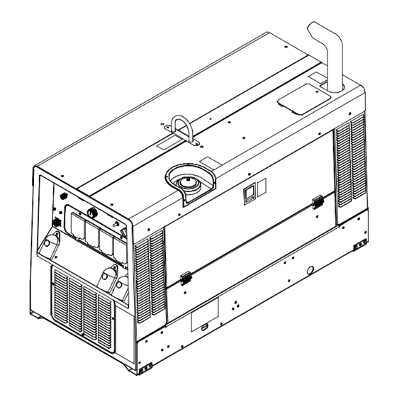
SECTION 12 − PARTS LIST Hardware is common and not available unless listed. Wirng harnesses are listed at the end of parts section. 3−Fig.15−5 1−Fig.15−3 101−Fig.15−2 Figure 12-1. Main Assembly OM-4422 Page 60... - Page 65 74−Fig.15−4 803 683-B OM-4422 Page 61...
- Page 66 Item Dia. Part Mkgs. Description Quantity Figure 12-1. Main Assembly ... . . Figure 12-3 Control Panel ........... .
- Page 67 Item Dia. Part Mkgs. Description Quantity Figure 12-1. Main Assembly (Continued) ....087341 Bumper, Door 1.000 Od X .750 High Rbr 50 Duro W/O .
- Page 68 Item Dia. Part Mkgs. Description Quantity Figure 12-1. Main Assembly (Continued) ....190207 Cable, Bat Pos 45 In Lg No 1 Awg W/Clamp & .406 Rng .
- Page 69 Hardware is common and not available unless listed. Wirng harnesses are listed at the end of parts section. 803 684-A Figure 12-2. Panel, Front w/Components Item Dia. Part Mkgs. Description Quantity Figure 12-2. Panel, Front w/Components (Figure 12-1 Item 101) .
- Page 70 Item Dia. Part Mkgs. Description Quantity Figure 12-2. Panel, Front w/Components (Continued) ....214543 Enclosure, Circuit Card Assy ........
- Page 71 Hardware is common and not available unless listed. Wirng harnesses are listed at the end of parts section. 803 689-B Figure 12-3. Control Panel Item Dia. Part Mkgs. Description Quantity Figure 12-3. Control Panel (Figure 12-1 Item 1) ..
- Page 72 Hardware is common and not available unless listed. Wirng harnesses are listed at the end of parts section. 17 16 803 686-A Figure 12-4. Generator Item Dia. Part Mkgs. Description Quantity Figure 12-4. Generator (Figure 12-1 Item 74) ..
- Page 73 Hardware is common and not available unless listed. Wirng harnesses are listed at the end of parts section. 803 685-A Figure 12-5. Rectifier Assembly Item Dia. Part Mkgs. Description Quantity Figure 12-5. Rectifier Assembly (Figure 12-1 Item 3) ....217081 Rectifier, Assembly (Includes) .
- Page 74 Note Some wiring harness components (switches, relays, circuit breakers) are also referenced elsewhere in this parts list. Purchase components separately or as part of the associated wiring harness. Item Dia. Part Mkgs. Description Quantity Wiring Harnesses ....219231 Harness, Engine Cat 3013c (Includes) .
- Page 75 Effective January 1, 2004 (Equipment with a serial number preface of “LE” or newer) This limited warranty supersedes all previous Miller warranties and is exclusive with no other Warranty Questions? guarantees or warranties expressed or implied. Call LIMITED WARRANTY − Subject to the terms and conditions Induction Heating Coils and Blankets below, Miller Electric Mfg.
-
Page 76: Options And Accessories
Distributor Address City State For Service Call 1-800-4-A-Miller or see our website at www.MillerWelds.com to locate a DISTRIBUTOR or SERVICE AGENCY near you. Always provide Model Name and Serial/Style Number. Contact your Distributor for: Welding Supplies and Consumables Options and Accessories...
Need help?
Do you have a question about the PRO 300 and is the answer not in the manual?
Questions and answers