Table of Contents
Advertisement
Deltaweld® 402, 602, 852 (50/60 Hz)
CV/DC Welding Power Sources For GMAW, FCAW, SAW Welding, And CAC-A Cutting And Gouging
Rated
Voltage
Model
Model
Welding
Welding
Range
Range
Output
300 A @ 32
300
(29) Volts
10 − 32
Amp
DC, 100%
Duty Cycle
450 A @ 38
450
(36.5) Volts
10 − 38
Amp
DC, 100%
Duty Cycle
650 A @ 44
650
Volts DC,
10 − 44
Amp
100% Duty
Cycle
*While idling
( ) Indicates specification differences for CE models
cover_om 4/95 − ST-800 453
OWNER'S
MANUAL
Deltaweld® 302, 452, 652 (60 Hz)
Max
IP
OCV
OCV
Rating
Rating
DC
DC
38
21M
(43)
48
21M
54
21M
©
1996 MILLER Electric Mfg. Co.
July 1996
Effective With Serial No. KG141349
Amperes Input at Rated Load Output, 50 or 60 Hz,
Three-Phase
200 V 230 V 380 V 400 V 440 V 460 V 575 V
42
27
25
--
3.2*
1.8*
1.7*
72
63
39
37
3.2*
2.7*
2.6*
2.2*
96
58
54
--
3.2*
3.3*
3.0*
Form: OM-223H
KVA
23
21
17
16.9
1.6*
1.6*
1.3*
1.26*
33
32
25
25.1
2.1*
1.4*
1.1*
1.09*
50
48
38
38.2
2.8*
1.6*
1.3*
1.26*
PRINTED IN USA
KW
12.9
0.21*
21.1
0.26*
34.2
0.35*
Advertisement
Table of Contents
Troubleshooting

Related Manuals for Miller DELTAWELD 302


Summary of Contents for Miller DELTAWELD 302
- Page 1 Volts DC, 10 − 44 3.2* 3.3* 3.0* 2.8* 1.6* 1.3* 1.26* 0.35* 100% Duty Cycle *While idling ( ) Indicates specification differences for CE models © cover_om 4/95 − ST-800 453 1996 MILLER Electric Mfg. Co. PRINTED IN USA...
- Page 3 Declaration of Conformity For European Community (CE) Products NOTE This information is provided for units with CE certification (see rating label on unit.) Miller Electric Mfg. Co. Manufacturer’s Name: 1635 W. Spencer Street Manufacturer’s Address: Appleton, WI 54914 USA Deltaweld® 402, 602, And 852...
-
Page 5: Section 1 − Definitions
SECTION 1 − DEFINITIONS 1-1. Warning Label Definitions Warning! Watch Out! There are possible hazards as shown by the symbols. Electric shock from welding electrode or wiring can kill. 1.1 Wear dry insulating gloves. Do not touch electrode with bare hand. Do not wear wet or damaged gloves. - Page 6 Warning! Watch Out! There are possible hazards as shown by the symbols. Electric shock from wiring can kill. Disconnect input plug or power before working on machine. Read the Owner’s Manual before working on this machine. Consult rating label for input power requirements, and check power available at the job site −...
-
Page 7: Manufacturer's Rating Labels For Ce Products
1-2. Manufacturer’s Rating Labels For CE Products Match label to one on unit. See Section 2-1. S-174 346 / S-174 347 / S-174 348 OM-223 Page 11... -
Page 8: Symbols And Definitions
1-3. Symbols And Definitions NOTE Some symbols are found only on CE products. Voltage Control/ Gas Metal Arc Amperes Temperature Panel Welding (GMAW) Output Circuit Breaker Remote Positive High Positive Low Negative Weld Inductance Weld Inductance Weld Input Output Terminal Output Terminal Output Terminal Protective Earth... -
Page 9: Selecting A Location
SECTION 2 − INSTALLATION 2-1. Selecting A Location Lifting Eye Lifting Forks Use lifting eye or lifting forks to move unit. Movement If using lifting forks, extend forks beyond opposite side of unit. Rating Label (Non CE Models Only) Use rating label to determine input power needs. -
Page 10: 115 Vac Receptacle And Circuit Breakers
2-3. Tipping Y Be careful when placing or moving unit over uneven surfaces. 2-4. 115 VAC Receptacle And Circuit Breakers Y Turn Off power before con- necting to receptacle. 115 V 15 A AC Receptacle Power is shared between RC9 and Remote 14 receptacle RC8 or terminal strip 1T (see Section 2-8). -
Page 11: Weld Output Terminals And Selecting Cable Sizes
2-5. Weld Output Terminals And Selecting Cable Sizes Y ARC WELDING can cause Electromagnetic Interference. To reduce possible interference, keep weld cables as short as possible, close together, and down low, such as on the floor. Locate welding operation 100 meters from any sensitive electronic equipment. Be sure this welding machine is installed and grounded according to this manual. -
Page 12: Remote Output Control
2-7. Remote 14 Receptacle RC8 And Terminal Strip 1T Information Socket Terminal Information 24 volts ac. Protected by circuit breaker CB2. 24 VOLTS AC 24 VOLTS AC Contact closure to A completes 24 volts ac contactor control circuit. Command reference; 0 to +10 volts dc. REMOTE OUTPUT CONTROL Remote control circuit common. -
Page 13: Placing Jumper Links And Connecting Input Power
2-9. Placing Jumper Links And Connecting Input Power 200 VOLTS 230 VOLTS 460 VOLTS Ref. S-174 976-A 230 VOLTS 460 VOLTS 575 VOLTS Ref. S-174 973-A 220 VOLTS 380 VOLTS 400 VOLTS 440 VOLTS (FACTORY OPTION) Ref. S-174 975-A Do not overtighten GND/PE jumper link nuts. -
Page 14: Section 3 − Operation
SECTION 3 − OPERATION 3-1. Controls Ref. ST-162 502-B Voltage Adjustment Control Remote Voltage Control Switch For front panel control of output, place switch in Panel position. For remote control of out- For front panel control, place switch in Panel Turn control clockwise to increase voltage. -
Page 15: Duty Cycle And Overheating
3-2. Duty Cycle And Overheating Duty Cycle is percentage of 10 min- utes that unit can weld at rated load without overheating. If unit overheats, thermostat(s) opens, output stops, and cooling fan runs. Wait fifteen minutes for unit to cool. Reduce amperage or duty cycle before welding. -
Page 16: Short Circuit Shutdown
4-2. Fuse F1 Y Turn Off power before open- ing rear access door. Fuse F1 (See parts List For Rating) Fuse F1 protects control transform- er from overload. If F1 opens, weld output and fan motor stops. Re- place F1. Tools Needed: 3/8 in Ref. -
Page 17: Section 5 − Safety Precautions For Arc Welding
SECTION 5 − SAFETY PRECAUTIONS FOR ARC WELDING safety_som1 4/95 OM-223H − 7/96 5-1. Symbol Usage Y Marks a special safety message. Means Warning! Watch Out! There are possible hazards with this procedure! The possible hazards are shown in the adjoining symbols. Means NOTE;... - Page 18 CYLINDERS can explode if damaged. 4. Never drape a welding torch over a gas cylinder. 5. Never allow a welding electrode to touch any cylinder. Shielding gas cylinders contain gas under high 6. Never weld on a pressurized cylinder − explosion will result. pressure.
-
Page 19: Principal Safety Standards
OVERUSE can cause OVERHEATED SIGNIFICANT DC VOLTAGE exists after EQUIPMENT. removal of input power on inverters. 1. Allow cooling period. 1. Turn Off inverter, disconnect input power, and 2. Reduce current or reduce duty cycle before discharge input capacitors according starting to weld again. -
Page 20: Section 6 − Electrical Diagram
SECTION 6 − ELECTRICAL DIAGRAM For Primary Circuit Diagram Portion, refer SC-181 304 to the Circuit Diagram located inside the wrapper of the welding power source. Figure 6-1. Circuit Diagram OM-223 Page 4... - Page 21 NOTES OM-223 Page 5...
-
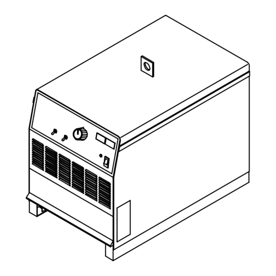
Page 22: Section 7 − Parts List
SECTION 7 − PARTS LIST ST-800 992-B Figure 7-1. Main Assembly (452 Model Illustrated) OM-223 Page 6... - Page 23 Quantity Model Item Dia. Part Mkgs. Description 302 452 652 Figure 7-1. Main Assembly ....+179 430 PANEL, side ......... . .
- Page 24 Quantity Model Item Dia. Part Mkgs. Description 302 452 652 Figure 7-1. Main Assembly (Continued) ... . 172 419 TRANSFORMER, pwr main 380/400/440 (consisting of) ..
- Page 25 Quantity Model Item Dia. Part Mkgs. Description 302 452 652 Figure 7-2. Panel, Front w/Components (Fig 7-1 Item 31) ....159 863 ELECTRONICS BOX ........
- Page 26 Quantity Model Item Dia. Part Mkgs. Description 302 452 652 Figure 7-2. Panel, Front w/Components (Fig 7-1 Item 31) (Continued) ..039 047 TERMINAL, pwr output red (consisting of) ....
- Page 27 Item Dia. Part Mkgs. Description Quantity 175 070 Figure 7-3. Rectifier, Si Diode (302 Model) (Fig 7-1 Item 32) ..C7-12 ..048 420 CAPACITOR, cer disc .01uf 1000VDC ......
- Page 28 Item Dia. Part Mkgs. Description Quantity Figure 7-5. Panel, Rear w/Components (Fig 7-1 Item 19) ....173 283 CHAMBER, plenum 14 in ........
-
Page 29: Options And Accessories
500 Amps. For more Dinse brand insulated female twist lock amperages (for Submerged Arc). information, see the Miller Coolant connector installs on output stud, GMAW/FCAW WELDING Systems literature sheet, Index No. providing quick disconnect of AY/7.2.
Need help?
Do you have a question about the DELTAWELD 302 and is the answer not in the manual?
Questions and answers
can i burn 1/16 wire with delta weld 302