Miller Spectrum 625 Owner's Manual
Hide thumbs
Also See for Spectrum 625:
- Owner's manual (44 pages) ,
- Owner's manual (40 pages) ,
- Owner's manual (52 pages)

Related Manuals for Miller Spectrum 625


Summary of Contents for Miller Spectrum 625
- Page 1 OM-2239 207 542C November 2002 Processes Air Plasma Cutting and Gouging Description Air Plasma Cutter Spectrum 625 And ICE-40C Torch Visit our website at www.MillerWelds.com...
- Page 2 We know you don’t have time to do it any other way. That’s why when Niels Miller first started building arc welders in 1929, he made sure his products offered long-lasting value and superior quality.
-
Page 3: Table Of Contents
TABLE OF CONTENTS SECTION 1 – SAFETY PRECAUTIONS - READ BEFORE USING ......1-1. Symbol Usage . -
Page 5: Section 1 - Safety Precautions - Read Before Using
SECTION 1 – SAFETY PRECAUTIONS - READ BEFORE USING pom _nd_9/98 1-1. Symbol Usage Means Warning! Watch Out! There are possible hazards with this procedure! The possible hazards are shown in the adjoining symbols. Y Marks a special safety message. This group of symbols means Warning! Watch Out! possible ELECTRIC SHOCK, MOVING PARTS, and HOT PARTS hazards. -
Page 6: Arc Rays Can Burn Eyes And Skin
If inside, ventilate the area and/or use exhaust at the arc to remove EXPLODING PARTS can injure. cutting fumes and gases. If ventilation is poor, use an approved air-supplied respirator. D On inverter power sources, failed parts can ex- Read the Material Safety Data Sheets (MSDSs) and the manufac- plode or cause other parts to explode when turer’s instruction for metals to be cut, coatings, and cleaners. -
Page 7: Additional Symbols For Installation, Operation, And Maintenance
1-3. Additional Symbols For Installation, Operation, And Maintenance HOT PARTS can cause severe burns. FIRE OR EXPLOSION hazard. D Do not touch hot parts bare handed. D Do not locate unit on, over, or near combustible surfaces. D Allow cooling period before working on torch. D Do not install unit near flammables. -
Page 8: Principal Safety Standards
1-4. Principal Safety Standards Safety in Welding and Cutting, ANSI Standard Z49.1, from American Safe Handling of Compressed Gases in Cylinders, CGA Pamphlet P-1, Welding Society, 550 N.W. LeJeune Rd, Miami FL 33126 from Compressed Gas Association, 1235 Jefferson Davis Highway, Suite 501, Arlington, VA 22202. -
Page 9: Section 1 - Consignes De Sécurité - Lire Avant Utilisation
SECTION 1 – CONSIGNES DE SÉCURITÉ – LIRE AVANT UTILISATION pom_nd_fre_9/98 1-1. Signification des symboles Signifie Mise en garde ! Soyez vigilant ! Cette procédure présente des risques de danger ! Ceux-ci sont identifiés par des symboles adjacents aux directives. Y Identifie un message de sécurité... - Page 10 Isoler la pince de masse quand pas mis à la pièce pour éviter le Tableau 1. Protection des yeux pour le coupage au plasma d’arc contact avec tout objet métallique. Il y a DU COURANT CONTINU IMPORTANT dans Intensité de courant en ampères Filtre de teinte (minimum) les convertisseurs après la suppression de l’ali- Moins de 20...
-
Page 11: Dangers Supplémentaires En Relation Avec L'installation, Le Fonctionnement Et La Maintenance
D Utilisez uniquement le ou les chalumeaux recommandés dans le ma- D Les bouteilles ne doivent pas être près de la zone de coupage ni de nuel de l’opérateur. tout autre circuit électrique. D Un contact électrique ne doit jamais se produire entre un chalumeau de plasma d’arc et une bouteille. -
Page 12: Principales Normes De Sécurité
1-4. Principales normes de sécurité Safety in Welding and Cutting, norme ANSI Z49.1, de l’American Wel- Safe Handling of Compressed Gases in Cylinders, CGA Pamphlet P-1, ding Society, 550 N.W. Lejeune Rd, Miami FL 33126 de la Compressed Gas Association, 1235 Jefferson Davis Highway, Suite 501, Arlington, VA 22202. -
Page 13: Section 2 - Definitions
SECTION 2 – DEFINITIONS 2-1. Symbols And Definitions Plasma Arc Cutting Adjust Air/Gas Low Air Pressure Amperes (PAC) Pressure Light No – Do Not Do Volts Increase Temperature This Protective Earth Single Phase Constant Current Voltage Input (Ground) Percent Direct Current Rated No Load Conventional Load Primary Voltage... -
Page 14: Section 3 - Installation
SECTION 3 – INSTALLATION 3-1. Specifications Amperes Input at Rated Maximum Rated Load Rated Type of Plasma Cutting Open-Circuit 50/60 Hz Output 50/60 Hz Output Output Output Output Capacity Voltage DC 208 V 230 V Direct 40 A @ 140 Air Or 0.5 in Current,... -
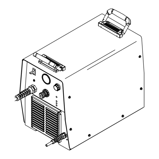
Page 15: Unit Dimensions, Weight, And Movement
3-5. Unit Dimensions, Weight, And Movement 17-1/4 in (438 mm) Dimensions And Weight 57 lb (25.9 kg) 15-1/4 in (387 mm) 10-1/4 in (260 mm) Lifting Handles Movement Use handles to lift unit. Hand Cart Y Do not move or operate unit Use cart or similar device to move where it could tip. -
Page 16: Connecting Work Clamp And Gas/Air Supply
3-6. Connecting Work Clamp and Gas/Air Supply Work Clamp Workpiece Connect work clamp to a clean, paint-free location on workpiece, as close to cutting area as possible. Use only clean, dry air with 90 to 150 psi (620 to 1035 kPa) pressure. -
Page 17: Electrical Service Guide
3-7. Electrical Service Guide 50/60 Hz Models Single Phase Input Voltage Input Amperes At Rated Output Max Recommended Standard Fuse Or Circuit Breaker Rating In Amperes Circuit Breaker , Time-Delay Normal Operating Min Input Conductor Size In AWG/Kcmil Max Recommended Input Conductor Length In Feet (Meters) (24) (30) Min Grounding Conductor Size In AWG/Kcmil... -
Page 18: Selecting A Location And Connecting Input Power
3-9. Selecting A Location And Connecting Input Power Rating Label Supply correct input power. Plug (NEMA Type 6-50P) Receptacle (NEMA Type 6-50R) Connect plug to receptacle. Input And Grounding 18 in (457 mm) of Y Do not move or operate unit Conductors space for airflow where it could tip. -
Page 19: Wiring Optional 240 Volt Plug (119 172) For Connection To Bobcat, Trailblazer Or Champion 10,000
3-10. Wiring Optional 240 Volt Plug (119 172) For Connection To Bobcat, Trailblazer Or Champion 10,000 Input And Grounding Conductors Plug Wired for 240 V, 2-Wire Load Neutral (Brass) Terminal And Tools Needed: Prong (Not Used) Load 1 (Brass)Terminal And Prong Load 2 (Brass) Terminal And Prong... -
Page 20: Installing Alternative Plug
3-11. Installing Alternative Plug This procedure is necessary if the unit is to be connected to a 208/230 VAC Supplied 230 VAC Plug receptacle that requires a plug that is different from the supplied plug. Cut cord close to plug. Alternative Plug (230 VAC Plug Shown) Input (Black Lead) -
Page 21: Section 4 - Operation
SECTION 4 – OPERATION 4-1. Controls Ref. 207 299 Output Control Power Switch At ambient temperatures below –55 C Use control to set cutting output. (235 readjustment gas/air The fan will normally run for pressure regulator may be necessary Place control in Gas/Air Set position to safely approximately 5 seconds after power (see Section 3-12). -
Page 22: Trigger Safety Lock
4-3. Trigger Safety Lock Trigger Trigger Locked Trigger Unlocked 801 397-A 4-4. Plasma Cutting System Practices The pilot arc starts immediately when trigger is pressed. Always connect work clamp to a clean, DO NOT start pilot arc without cutting or Set correct air pressure for process: paint-free location on workpiece, as close to gouging as this shortens the service life... -
Page 23: Sequence Of Cutting Operation
4-5. Sequence Of Cutting Operation Connect work clamp to a clean, paint-free Set air pressure to 75 PSI (517 kPa) for cutting. location on workpiece, as close to cutting area as possible. The pilot arc starts immediately when trigger is pressed. °... -
Page 24: Sequence Of Gouging Operation
4-6. Sequence Of Gouging Operation Connect work clamp to a clean, paint-free Set air pressure to 55 PSI (379 kPa) for gouging. location on workpiece, as close to cutting area as possible. The pilot arc starts immediately when trigger is pressed. Hold torch at approximately Raise trigger lock and press trigger. -
Page 25: Sequence Of Piercing Operation
4-7. Sequence Of Piercing Operation The pilot arc starts immediately when trigger is pressed. Connect work clamp to a clean, paint-free Set air pressure to 75 PSI Hold torch at an angle to the location on workpiece, as close to cutting workpiece. -
Page 26: Section 5 - Maintenance & Troubleshooting
SECTION 5 – MAINTENANCE & TROUBLESHOOTING 5-1. Routine Maintenance Y Disconnect power Maintain more often before maintaining. during severe conditions. Each Use Check Torch Check Gas/Air Tip, Electrode, Pressure And Shield Cup Every Week Check Shield Cup Shutdown System 3 Months Service Air Replace Filter/Regulator... -
Page 27: Overload Protection: Status Lights & Checking Shield Cup Shutdown System
5-2. Overload Protection: Status Lights & Checking Shield Cup Shutdown System If certain problems occur, a status light comes on, and output stops. Pressure Light Lights if gas/air pressure is below 40 PSI (276 kPa). Turn power Off, and check for proper gas/air pressure (see... -
Page 28: Checking/Replacing Retaining Cup, Tip, And Electrode
5-3. Checking/Replacing Retaining Cup, Tip, And Electrode Overtightening will strip threads. Do not overtighten retaining cup during assembly. Do not cross-thread parts causing stripping. Use care during torch assembly and parts replacement. Inspect shield cup, tip, and electrode for wear before cutting or whenever cutting speed has been significantly reduced. -
Page 29: Torch And Work Cable Replacement
5-4. Torch And Work Cable Replacement If torch or work cable needs to be removed Slide torch cable, connector, and plugs Slide work cable through nut and out of unit. or replaced, proceed as follows: through nut and out of unit. Retain nut for Retain nut for use on replacement strain use on replacement strain relief. -
Page 30: Troubleshooting Power Source
5-5. Troubleshooting Power Source Press torch trigger and check if pilot arc ignites. Check torch consumables. Does pilot arc *Check torch connections, Is Power switch ignite? Place Power switch in the air filter, pressure switch S3, S1 in the On On position. -
Page 31: Troubleshooting Torch
5-6. Troubleshooting Torch Torch travel speed too slow; increase travel speed (see Section 4-5). Clean Does arc go replace torch consumables Go to Section 5-5. as necessary (see Section while cutting? 5-3). Be sure work clamp is securely attached workpiece. Be sure work clamp is securely attached to work- piece. -
Page 32: Section 6 - Electrical Diagram
SECTION 6 – ELECTRICAL DIAGRAM 205 723 Figure 6-1. Circuit Diagram OM-2229 Page 28... -
Page 33: Section 7 - Parts List
SECTION 7 – PARTS LIST Hardware is common and not available unless listed. 803 223 Figure 6-1. Main Assembly OM-2239 Page 29... - Page 34 207296 XFMR,MAIN SPECTRUM 625 ........
- Page 35 NOTE: The ICE-40C torch is specifically for use Item Part Description only with this plasma cutting unit. 195 110 ICE-40C 25ft Torch 195 111 ICE-40C 50ft Torch 183 427 Handle Assy, complete (1) 192 059 Main Body (1) 209 298 Leads, 25ft (1) 209 299 Leads, 50ft (1)
-
Page 36: Warranty
For extended tip use, set Amperage control to 35. Drag Shield Retaining Cup Electrode Swirl Ring O –Ring 204 323 192 050 204 325 192 047 169 232 192 049 Standard Cutting Apply silicone grease (169 231) Deflector Retaining Cup 35A Tip Electrode before installing. - Page 37 Notes Work like a Pro! Pros weld and cut safely. Read the safety rules at the beginning of this manual.
- Page 38 Notes...
- Page 39 Effective January 1, 2002 (Equipment with a serial number preface of “LC” or newer) This limited warranty supersedes all previous Miller warranties and is exclusive with no other Warranty Questions? guarantees or warranties expressed or implied. Call LIMITED WARRANTY – Subject to the terms and conditions APT, ZIPCUT &...
- Page 40 Distributor Address City State For Service Call 1-800-4-A-Miller or see our website at www.MillerWelds.com to locate a DISTRIBUTOR or SERVICE AGENCY near you. Always provide Model Name and Serial/Style Number. Contact your Distributor for: Welding Supplies and Consumables Options and Accessories...
Need help?
Do you have a question about the Spectrum 625 and is the answer not in the manual?
Questions and answers