Table of Contents
Troubleshooting

Related Manuals for Miller Dimension 650 CE


Summary of Contents for Miller Dimension 650 CE
- Page 1 OM-272476H 2019-05 Processes Multiprocess Welding Description Arc Welding Power Source Dimension 650 File: MULTIPROCESS For product information, Owner’s Manual translations, and more, visit www.MillerWelds.com...
- Page 2 We know you don’t have time to do it any other way. That’s why when Niels Miller first started building arc welders in 1929, he made sure his products offered long-lasting value and superior quality.
-
Page 3: Table Of Contents
TABLE OF CONTENTS SECTION 1 − SAFETY PRECAUTIONS - READ BEFORE USING ....... . . 1-1. - Page 4 TABLE OF CONTENTS SECTION 8 − GMAW/FCAW OPERATION ............8-1.
- Page 5 DECLARATION OF CONFORMITY for European Community (CE marked) products. MILLER Electric Mfg. Co., 1635 Spencer Street, Appleton, WI 54914 U.S.A. declares that the product(s) identified in this declaration conform to the essential requirements and provisions of the stated Council Directive(s) and Standard(s).
- Page 6 EMF DATA SHEET FOR ARC WELDING POWER SOURCE Product/Apparatus Identification Product Stock Number DIMENSION 650 380/400V 50/60HZ CE 907618 Compliance Information Summary Applicable regulation Directive 2014/35/EU Reference limits Directive 2013/35/EU, Recommendation 1999/519/EC Applicable standards IEC 62822-1:2016, IEC 62822-2:2016 Intended use for occupational use for use by laymen Non-thermal effects need to be considered for workplace assessment...
-
Page 7: Section 1 − Safety Precautions - Read Before Using
SECTION 1 − SAFETY PRECAUTIONS - READ BEFORE USING som 2018−01 Protect yourself and others from injury — read, follow, and save these important safety precautions and operating instructions. 1-1. Symbol Usage DANGER! − Indicates a hazardous situation which, if Indicates special instructions. - Page 8 D Do not cut or weld on tire rims or wheels. Tires can explode if heat- FUMES AND GASES can be hazardous. ed. Repaired rims and wheels can fail. See OSHA 29 CFR 1910.177 listed in Safety Standards. D Do not weld on containers that have held combustibles, or on Welding produces fumes and gases.
-
Page 9: Additional Symbols For Installation, Operation, And Maintenance
D Never weld on a pressurized cylinder − explosion will result. CYLINDERS can explode if damaged. D Use only correct compressed gas cylinders, regulators, hoses, and fittings designed for the specific application; maintain them Compressed gas cylinders contain gas under high and associated parts in good condition. -
Page 10: California Proposition 65 Warnings
H.F. RADIATION can cause interference. ARC WELDING can cause interference. D High-frequency (H.F.) can interfere with radio D Electromagnetic energy can interfere with navigation, safety services, computers, and sensitive electronic equipment such as communications equipment. computers and computer-driven equipment such as robots. D Have only qualified persons familiar with electronic equipment D Be sure all equipment in the welding area is electromagnetically perform this installation. -
Page 11: Section 2 − Consignes De Sécurité − Lire Avant Utilisation
SECTION 2 − CONSIGNES DE SÉCURITÉ − LIRE AVANT UTILISATION som_2018−01_fre Pour écarter les risques de blessure pour vous−même et pour autrui — lire, appliquer et ranger en lieu sûr ces consignes relatives aux précautions de sécurité et au mode opératoire. 2-1. - Page 12 D Déplacer toutes les substances inflammables à une distance de LES PIÈCES CHAUDES peuvent 10,7 m de l’arc de soudage. En cas d’impossibilité les recouvrir provoquer des brûlures. soigneusement avec des protections homologués. D Ne pas toucher à mains nues les parties chaudes. D Ne pas souder dans un endroit là...
-
Page 13: Dangers Supplémentaires En Relation Avec L'installation, Le Fonctionnement Et La Maintenance
D Protéger les bouteilles de gaz comprimé d’une chaleur excessive, Les CHAMPS ÉLECTROMAGNÉTIQUES (CEM) des chocs mécaniques, des dommages physiques, du laitier, des peuvent affecter les implants médicaux. flammes ouvertes, des étincelles et des arcs. D Placer les bouteilles debout en les fixant dans un support station- D Les porteurs de stimulateurs cardiaques et naire ou dans un porte-bouteilles pour les empêcher de tomber ou autres implants médicaux doivent rester à... -
Page 14: Proposition Californienne 65 Avertissements
D Effectuer régulièrement le contrôle et l’entretien de l’installation. LIRE LES INSTRUCTIONS. D Maintenir soigneusement fermés les portes et les panneaux des sources de haute fréquence, maintenir les éclateurs à une distan- D Lire et appliquer les instructions sur les ce correcte et utiliser une terre et un blindage pour réduire les étiquettes et le Mode d’emploi avant l’instal- interférences éventuelles. -
Page 15: Section 3 − Definitions
SECTION 3 − DEFINITIONS 3-1. Additional Safety Symbols And Definitions Some symbols are found only on CE products. Warning! Watch Out! There are possible hazards as shown by the symbols. Safe1 2012−05 Do not discard product (where applicable) with general waste. Reuse or recycle Waste Electrical and Electronic Equipment (WEEE) by disposing at a designated collection facility. - Page 16 Welding sparks can cause fires. Have a fire extinguisher nearby, and have a watchperson ready to use it. Safe14 2012−05 Do not weld on drums or any closed containers. Safe16 2017−04 Do not remove or paint over (cover) the label. Safe20 2017−04 Flying pieces of parts can cause injury.
-
Page 17: Miscellaneous Symbols And Definitions
Kasjf;laksf;lkasdf'l;aksdf;lkasd;flksadflkasd;lk Kasjf;laksf;lkasdf'l;aksdf;lkasd;flksadflkasd;lk Kasjf;laksf;lkasdf'l;aksdf;lkasd;flksadflkasd;lk Become trained and read the instructions before working on the machine or welding. Safe40 2012−05 Hazardous voltage remains on input capacitors after power is turned off. Do not touch fully charged capacitors. Always wait 60 seconds after power is turned off before working on unit, AND check input ca- pacitor voltage, and be sure it is near 0 before touching any parts. -
Page 18: Section 4 − Specifications
SECTION 4 − SPECIFICATIONS 4-1. Features And Benefits LVCt Line Voltage Compensation is circuitry that keeps the power source output constant regardless of input power fluctuation. Wind Tunnel Technologyt circulates air over components that require cooling, not over electronic circuitry, which reduces contaminants and im- proves reliability in harsh welding environments. -
Page 19: Dimensions And Weight
B. Output Range Process Output Range Rated No-Load Voltage (U 380 VAC 460 VAC GTAW (Lift-Arc TIG) Output On 10A−815A GTAW (TIG) Remote 10A−815A SMAW (Stick) Remote 30A−815A Output On 30A−815A 65V* 79V* CAC-A (Gouge) Output On 30A−815A 65V* 79V* GMAW/FCAW (Gas) Remote 10V−44V... -
Page 20: Duty Cycle And Overheating
C. Information On Electromagnetic Compatibility (EMC) This Class A equipment is not intended for use in residential locations where the electrical power is provided by the public low− voltage supply system. There can be potential difficulties in ensuring electromagnetic compatibility in those locations, due to con- ducted as well as radiated disturbances. -
Page 21: Section 5 − Installation
SECTION 5 − INSTALLATION 5-1. Selecting A Location Movement Do not move or operate unit where it could tip. Location And Airflow Special installation may be required where gasoline or volatile liquids are present − see NEC Article 511 or CEC Section 20. -
Page 22: Selecting Cable Sizes
5-2. Selecting Cable Sizes* NOTICE − The Total Cable Length in Weld Circuit (see table below) is the combined length of both weld cables. For example, if the power source is 100 ft (30 m) from the workpiece, the total cable length in the weld circuit is 200 ft (2 cables x 100 ft). Use the 200 ft (60 m) column to determine cable size. -
Page 23: Connecting Weld Output Cables
5-4. Connecting Weld Output Cables Tools Needed: 269322-A 3/4 in. (19 mm) Weld Output Terminal nals to weld output terminal with nut and Turn off power before connecting to bolt as shown, so that weld cable terminal weld output terminals. Supplied Weld Output Terminal Nut is tight against copper bar. -
Page 24: Supplementary Protector
5-6. Supplementary Protector 115 V 20 Amp AC Receptacle Supplementary Protector CB1 Supplementary Protector CB2 CB1 protects duplex receptacle. CB2 protects 24 volts AC portion of Remote receptacle from overload. Press button to reset supplement- ary protector. Ref 272773-A 5-7. Electrical Service Guide Elec Serv 2017−01 NOTICE −... - Page 25 Notes OM-272476 Page 19...
-
Page 26: Connecting Input Power
5-8. Connecting Input Power = GND/PE Earth Ground U (L1) V (L2) W (L3) U (L1) V (L2) W (L3) Tools Needed: 3/8 in. 3/16 in. Input12 2016−06 / Ref. 803766-C / 272784-A OM-272476 Page 20... - Page 27 5-8. Connecting Input Power (Continued) national, state, and local electrical codes. If Connect input conductors to welding power Turn Off welding power source. applicable, use lugs of proper amperage source line terminals. Installation must meet all National capacity and correct hole size. Close input power cover and secure with and Local Codes −...
-
Page 28: Section 6 − General Operation
SECTION 6 − GENERAL OPERATION 6-1. Front Panel 263561-B / Ref. 269321-B Arc Control Weld process operation sections de- The meters display the actual weld output scribe functionality of the identified items values after arc initiation and remains dis- Remote In Use Indicator (See Sections 7-1 thru 9-4). -
Page 29: Mode Switch Settings
6-2. Mode Switch Settings Switch Position Process Output Control Panel Adjust Remote Adjust GMAW/FCAW Gas Output On Volts Volts FCAW−S No-Gas Output On Volts Volts No Remote Adjust - SMAW Stick Output On Amps Panel Only* No Remote Adjust - CAC−A Gouge Output On Amps... -
Page 30: Alternate Configuration Functions
6-4. Alternate Configuration Functions The function of the remote control and panel meters can be changed on this machine. To view or change the active configuration: S Place the process selection switch into SMAW (Stick) Output-On mode. S Quickly tap (press and release) the wire feeder gun trigger or remote output on-off switch 3 to 5 times within a few seconds to view the active configuration. -
Page 31: Section 7 − Gtaw Operation
SECTION 7 − GTAW OPERATION 7-1. Typical Connection For GTAW Process 269325-B Remote 14 Receptacle Gas Hose Turn off power before making con- nections. Negative (−) Weld Output Terminal Connect desired remote control to Remote 14 receptacle if required. Foot Control TIG Torch Positive (+) Weld Output Terminal Gas Cylinder... -
Page 32: Gtaw - Tig Remote Welding Mode
7-2. GTAW - TIG Remote Welding Mode 263561-B Setup Operation Weld terminals are energized through the remote control in For typical system connections refer to The Adjust Control is used to set desired GTAW - TIG Remote welding mode. Section 7-1. preset amperage. -
Page 33: Gtaw - Lift-Arc Tig Output-On Welding Mode
7-3. GTAW - Lift-Arc TIG Output-On Welding Mode 12.0 263561-B 1 − 2 “Touch” Seconds Do NOT Strike Like A Match! Setup Operation Weld terminals are energized at all times in GTAW - Lift-Arc TIG Out- For typical system connections refer to The Adjust Control is used to set desired put-On welding mode. -
Page 34: Section 8 − Gmaw/Fcaw Operation
SECTION 8 − GMAW/FCAW OPERATION 8-1. Typical Connection For Remote Control Feeder GMAW/FCAW Process 269323-B Workpiece Use of shielding gas is dependant on Wire Turn off power before making Type. connections. Remote 14-Receptacle The connection diagram illustrates Wire Feeder DCEP (reverse polarity) suitable for all Positive (+) Weld Output Terminal wires except self-shielded FCAW. -
Page 35: Gmaw/Fcaw - Remote Welding Mode
8-2. GMAW/FCAW - Remote Welding Mode 25.0 263561-B Rotate Mode Switch to GMAW/FCAW trol will override the Adjust Control of Weld terminals are energized Remote position as shown. preset voltage on the welding power through the remote control in source. The Remote In Use indicator GMAW/FCAW Remote welding The preset voltage is shown in the Left Dis- will be lit. -
Page 36: Typical Connection For Voltage-Sensing Feeder Gmaw/Fcaw Process
8-3. Typical Connection For Voltage-Sensing Feeder GMAW/FCAW Process 269324-B Use of shielding gas is dependant on Wire Turn off power before making con- Type. nections. Gun Trigger Receptacle Positive (+) Weld Output Terminal The connection diagram illustrates Negative (−) Weld Output Terminal Wire Feeder DCEP (reverse polarity) suitable for all Ground Cable to Workpiece... -
Page 37: Gmaw/Fcaw - (Gas) Output-On Welding Mode
8-4. GMAW/FCAW - (Gas) Output-On Welding Mode 25.0 263561-B Setup Weld terminals are energized at all The Left Display toggling momentarily times in GMAW/FCAW (Gas) Out- For typical system setup connections refer pauses while the preset voltage is ad- put-On welding mode. to Section 8-3. -
Page 38: Fcaw-S (No Gas) Output-On Welding Mode
8-5. FCAW-S (No Gas) Output-On Welding Mode 25.0 263561-B Setup Weld terminals are energized at all The Left Display toggling momentarily times in FCAW-S (No Gas) Out- For typical system setup connections refer pauses while the preset voltage is ad- put-On welding mode. -
Page 39: Section 9 − Smaw/Cac-A Operation
SECTION 9 − SMAW/CAC-A OPERATION 9-1. Typical Connection For SMAW And CAC-A Process 269326-B cutting torch to positive weld output termi- Connect desired remote control to remote Turn off power before making con- nal. 14 receptacle as required. nections. Electrode Holder Compressed Air LIne Electrode Holder (Carbon Arc) -
Page 40: Smaw - Stick Remote Welding Mode
9-2. SMAW - Stick Remote Welding Mode 263561-B Operation Arc Control Weld terminals are energized through the remote control in The Adjust Control is used to set desired Arc control allows the arc characteristics, SMAW - Stick Remote welding preset amperage. soft versus stiff, to be changed for specific mode. -
Page 41: Smaw - Stick Output-On Welding Mode
9-3. SMAW - Stick Output-On Welding Mode 65.0 263561-B The open circuit voltage is shown in the Left Arc Control Weld terminals are energized at all Display and the preset amperage is shown times in SMAW - Stick Output-On Arc control allows the arc characteristics, in the Right Display. -
Page 42: Cac-A - Gouge Output-On Mode
9-4. CAC-A - Gouge Output-On Mode 65.0 263561-B Setup Operation Weld terminals are energized at all times in CAC-A - Gouge Output-On For typical system connections refer to The Adjust Control is used to set desired welding mode. Section 9-1. preset amperage. -
Page 43: Section 10 − Saw Operation
SECTION 10 − SAW OPERATION 10-1. Typical Connection For SAW Process Power Source Back View Power Source Front View 269792-A Ground Cable to Workpiece Saw Control Turn off power before making con- Workpiece Flux System nections. Wire Drive Assembly Flux Valve Positive (+) Weld Output Terminal Negative (−) Weld Output Terminal 10 Pin Motor Control Cord... -
Page 44: Saw - Subarc Remote Welding Mode
Adjust Control SAW Controller the Adjust Control of preset voltage on the Setup When using Miller Electric HDC DX con- welding power source. The Remote In Use For typical system connections refer to troller, select Dimension 652 or SubArc DC indicator will be lit. -
Page 45: Section 11 − Maintenance & Troubleshooting
SECTION 11 − MAINTENANCE & TROUBLESHOOTING 11-1. Routine Maintenance Disconnect power Maintain more often before maintaining. during severe conditions. 3 Months Repair Or Replace Replace Cracked Replace Damaged Or Torch Body Cracked Unreadable Cables Labels Repair Or Replace Cracked Cables And Cords Clean Tighten Weld... -
Page 46: Help Displays
11-3. Help Displays All directions are in reference to the front HELP of the unit. All circuitry referred to is lo- cated inside the unit. HELP Help 1, 6, 7 Display HELP Indicates a malfunction in the primary power circuit. If this display is shown, contact a Fac- tory Authorized Service Agent. -
Page 47: Troubleshooting
11-4. Troubleshooting Trouble Remedy No weld output; unit completely inop- Place line disconnect switch in On position (see Section 5-8). erative. Check and replace line fuse(s), if necessary, or reset circuit breaker (see Section 5-8). Check for proper input power connections (see Section 5-8). No weld output;... -
Page 48: Section 12 − Electrical Diagrams
SECTION 12 − ELECTRICAL DIAGRAMS Figure 12-1. Circuit Diagram For Dimension 650 CC/CV 380/400V OM-272476 Page 42... - Page 49 272471-A OM-272476 Page 43...
-
Page 50: Section 13 − Parts List
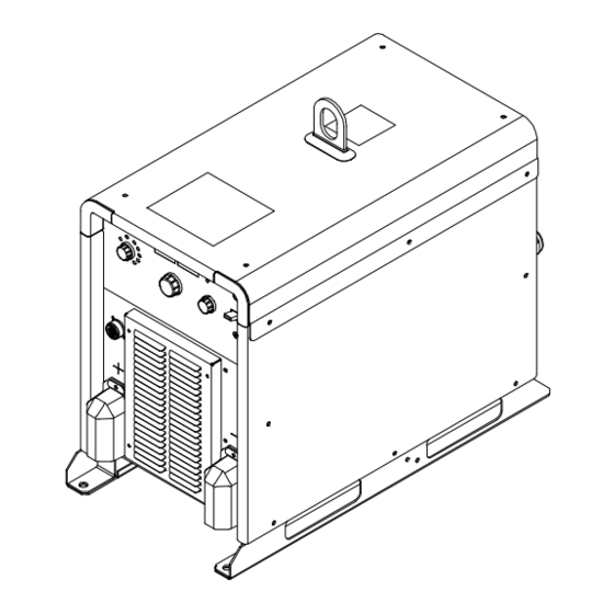
SECTION 13 − PARTS LIST Hardware is common and not available unless listed. 8 (Fig 13-4) 34 (Fig 13-5) 4 (Fig 13-2) 31 (Fig 13-3) 272811-C Figure 13-1. Main Assembly OM-272476 Page 44... - Page 51 ..Label, Miller (Not Shown) ........
- Page 52 ....263561 Label, Nameplate Miller Dimension 650 ......
- Page 53 Hardware is common and not available unless listed. 275944-B Figure 13-3. Wind Tunnel, RH Item Dia. Part Mkgs. Description Quantity Figure 13-3. Wind Tunnel, RH ....263555 Heat Sink, Power Module .
- Page 54 Hardware is common and not available unless listed. 272803-A Figure 13-4. Wind Tunnel, LH Item Dia. Part Mkgs. Description Quantity Figure 13-4. Wind Tunnel, LH ... . . +263569 Windtunnel, Lh .
- Page 55 Hardware is common and not available unless listed. 272926-B Figure 13-5. Rear Panel Assembly Item Dia. Part Mkgs. Description Quantity Figure 13-5. Rear Panel Assembly ..272312 Circuit Card Assy, Input Filter ........
- Page 56 Notes...
- Page 57 Notes Start Your Professional Over 80,000 trained 400 Trade Square East, Troy, Ohio 45373 Welding Career Now! since 1930! 1-800-332-9448 www.welding.org...
- Page 58 Notes...
- Page 59 Effective January 1, 2019 (Equipment with a serial number preface of MK or newer) This limited warranty supersedes all previous Miller warranties and is exclusive with no other guarantees or warranties expressed or implied. LIMITED WARRANTY − Subject to the terms and conditions Subarc Wire Drive Assemblies below, Miller Electric Mfg.
- Page 60 Contact the Delivering Carrier to: File a claim for loss or damage during shipment. For assistance in filing or settling claims, contact your distributor and/or equipment manufacturer’s Transportation Department. © ORIGINAL INSTRUCTIONS − PRINTED IN USA 2019 Miller Electric Mfg. LLC 2019−01...
Need help?
Do you have a question about the Dimension 650 CE and is the answer not in the manual?
Questions and answers