Canon ImageRunner 2545i Reference Manual
Hide thumbs
Also See for ImageRunner 2545i:
- Sending and facsimile manual (321 pages) ,
- System settings manual (314 pages) ,
- Printer manual (148 pages)
Table of Contents
Advertisement
Quick Links
Download this manual
See also:
User Manual
Advertisement
Table of Contents

Related Manuals for Canon ImageRunner 2545i


Summary of Contents for Canon ImageRunner 2545i
- Page 1 Reference Guide Reference Guide Please read this guide before operating this product. After you finish reading this guide, store it in a safe place for future reference.
- Page 2 imageRUNNER 2545i/2545 2535i/2535 2530i/2530 2525i/2525 2520i/2520 Reference Guide...
-
Page 3: Manuals For The Machine
Manuals for the Machine The manuals for this machine are organized as shown below. Please refer to them for detailed information. Some manuals may not be needed for certain system configurations and products purchased. Guides with this symbol are PDF manuals included on the Guides with this symbol are printed manuals. - Page 4 Considerable effort has been made to ensure that this manual is free of inaccuracies and omissions. However, as we are constantly improving our products, if you need an exact specification, please contact Canon.
-
Page 5: Table Of Contents
Contents Preface ............ix How to Use This Manual . - Page 6 Placing Originals ..........2-14 Document Sizes.
- Page 7 Chapter 4 Optional Equipment System Configuration ..........4-2 Optional Equipment .
- Page 8 Requesting Repairs from the Control Panel ......6-65 Contacting Your Local Authorized Canon Dealer..... . 6-67...
- Page 9 Chapter 7 Appendix Additional Functions Settings Table ....... . .7-2 Available Paper Stock .
-
Page 10: Preface
Preface Thank you for purchasing the Canon imageRUNNER 2545i/2545/2535i/2535/2530i/2530/ 2525i/2525/2520i/2520. Please read this manual thoroughly before operating the machine to familiarize yourself with its capabilities, and to make the most of its many functions. After reading this manual, store it in a safe place for future reference. -
Page 11: Illustrations Used In This Manual
Illustrations Used in This Manual The machine illustrations used in this manual are those of the imageRUNNER 2545i with the following optional equipment attached: the Inner Finisher-B1, Inner Finisher Additional Tray-B1, and CST. Feeding Unit-AE1. Displays Used in This Manual Screen shots used in this manual may differ from actual displays depending on the machine configuration. -
Page 12: Abbreviations Used In This Manual
Abbreviations Used in This Manual In this manual, product names are abbreviated as follows: Microsoft Windows 2000 operating system: Windows 2000 Microsoft Windows XP operating system: Windows XP Microsoft Windows Vista operating system: Windows Vista Microsoft Windows 7 operating system: Windows 7 Microsoft Windows Server 2003 operating system: Windows Server 2003... - Page 13 Scanning Scanning an original to be copied or sent to a client computer, fax machine, etc. Printing Outputting documents such as a copy, fax, or data sent from a client computer to the machine. Copying Printing data scanned from an original, followed by finishing options, such as stapling.
-
Page 14: Legal Notices
SOFTWARE to you for any intellectual property of rights holders of the SOFTWARE. (3) You may use the SOFTWARE solely for use with the Canon product you purchased (the “PRODUCT”). (4) You may not assign, sublicense, market, distribute, or transfer the SOFTWARE to any third party without prior written consent of rights holders of the SOFTWARE. -
Page 15: Disclaimers
Disclaimers The information in this document is subject to change without notice. CANON INC. MAKES NO WARRANTY OF ANY KIND WITH REGARD TO THIS MATERIAL, EITHER EXPRESS OR IMPLIED, EXCEPT AS PROVIDED HEREIN, INCLUDING WITHOUT LIMITATION, THEREOF, WARRANTIES AS TO MARKETABILITY, MERCHANTABILITY, FITNESS FOR A PARTICULAR PURPOSE OR USE OR NON-INFRINGEMENT. -
Page 16: Introduction To Imagerunner 2545 Series
Introduction to imageRUNNER 2545 Series CHAPTER This chapter provides an overview of the machine, including basic functions and part names. What This Machine Can Do ..........1-2 Parts and Their Functions. -
Page 17: What This Machine Can Do
Equipped with features that meet the needs of document work in a digitized office, the imageRUNNER 2545i/2545/2535i/2535/2530i/2530/2525i/2525/2520i/2520 represents the ultimate in digital multitasking machines. Copying... - Page 18 Faxing* The machine’s Super G3 fax function is Original compatible with most Super G3 fax machines used in office environments. If the optional Super G3 Fax Board-AG1 and Fax Driver are installed, you can send facsimiles from your computer. (See the Sending and Facsimile Guide.) * The Fax function is available only when the optional Super G3 Fax Board-AG1 is attached to the machine.
-
Page 19: Network Scanning
Network Scanning The Remote Scan function enables you to use the machine as a conventional scanner. You can scan a document using the machine, and read the data in a TWAIN-compliant application on your computer. To use this function, the machine must be connected to an IPv4 network and the Color Network ScanGear* must be installed on your computer. -
Page 20: Energy Conservation
Energy Conservation You can conserve power efficiently by setting the Sleep mode and the Auto Shutdown Time setting. You can put the machine into the Sleep mode manually by pressing the control panel power switch, or you can specify a preset time for the machine to enter the Sleep mode. -
Page 21: Parts And Their Functions
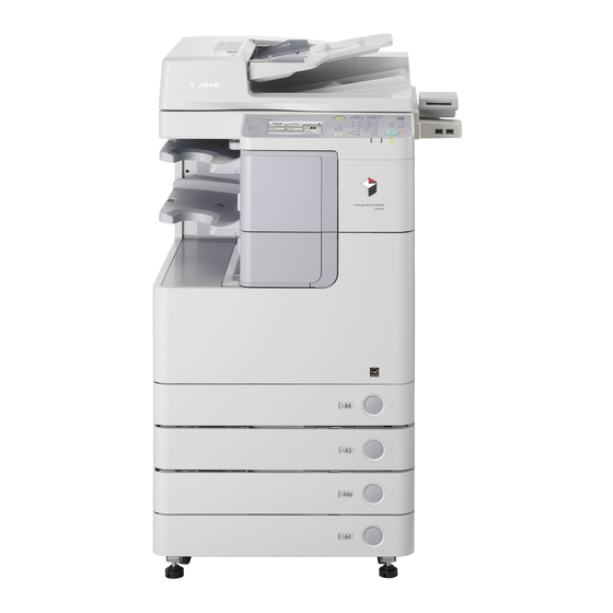
For more information on the optional equipment, see Chapter 4, “Optional Equipment.” External View The imageRUNNER 2545i with the The imageRUNNER 2520 with the optional Inner Finisher-B1, Inner optional Inner 2 Way Tray-G1, Finisher Additional Tray-B1, and CST. - Page 22 a Main Power Switch e Stack Bypass Press to the “I” side to turn ON the machine. (See Use the stack bypass to feed paper manually, Chapter 2, “Before You Start Using the Machine,” and for loading nonstandard paper stock, such as in the User’s Guide.) envelopes.
-
Page 23: Internal View
Internal View The imageRUNNER 2545i with the optional Inner Finisher-B1, Inner Finisher Additional Tray-B1, and CST. Feeding Unit-AE1 attached. a Front Cover h Right Cover Open this cover to replace the waste toner Open this cover when clearing a paper jam inside container. -
Page 24: Control Panel
Control Panel a Touch panel display h Volume Control key The menu screen for each function is Press to set the machine’s audible tone settings. displayed here. (See “Using the Touch Panel (See “Volume Control,” on p. 2-30.) Display,” on p. 2-2.) i Counter Check key b Display Contrast dial Press to view the machine’s print/scan page counts. - Page 25 1-10 Parts and Their Functions...
-
Page 26: Basic Operations
Basic Operations CHAPTER This chapter describes information you should know before using the machine’s various functions. Using the Touch Panel Display ..........2-2 Selecting the Desired Function . -
Page 27: Using The Touch Panel Display
Using the Touch Panel Display The touch panel display on the control panel enables you to access and make settings by touching the screen directly. For example, if you wish to view and select from the Finishing options, press [Finishing] directly on the display. The machine will display the available Finishing options. -
Page 28: Selecting The Desired Function
Selecting the Desired Function By default, the machine is set to display the top screen of the Copy function when you turn ON the machine. (See “Initial Function at Power ON,” on p. 3-2.) If you wish to use other functions, such as Send and Remote Scan, you need to switch the display to the screen of the desired function. -
Page 29: Entering Characters
When certain modes are set, the characters on some keys may become grayed out and unavailable for selection. This means that the Grayed out settings or modes corresponding with these (Not available for selection) keys cannot be selected in combination with the presently set settings or modes. -
Page 30: Entering Numbers
Entering Numbers Whenever the numeric keys icon ( ) is displayed on the screen, you can use (numeric keys) on the control panel to enter a number. Entering Alphanumeric Characters Whenever the on-screen keyboard is displayed, you are expected to enter alphanumeric characters. - Page 31 ❑ To enter symbols, select [Other]. Enter the desired characters. ● When the entry mode is [Alphabet]: ❑ Press the keys for the desired characters. To enter uppercase letters, press [Shift] ➞ enter the desired letters. ● When the entry mode is [Other]: ❑...
-
Page 32: Entering Characters Using A Usb Keyboard
❑ Press the key for the desired symbol. NOTE • If you make a mistake when entering a character, press [ ] or [ ] to position the cursor on the right side of the incorrect character ➞ press [Backspace] to delete the character ➞... - Page 33 ■ Using a USB Keyboard Entering characters using the USB keyboard is easy. However, keep in mind the following differences from the on-screen keyboard: • Only ASCII characters can be entered from the USB keyboard. • You do not need to change the entry mode. When the entry mode drop-down list is displayed on the screen, you cannot enter characters from the USB keyboard.
-
Page 34: Logging In To The Machine
Logging in to the Machine The machine is equipped with various security functions that help you protect the machine from unauthorized access. If the machine is managed with department IDs or user IDs, you must log in to the machine before using it. Entering the Department ID and Password If Department ID Management has been set, you must enter your department ID (and password) to log in to the machine. - Page 35 Press (Log In/Out) on the control panel. The top screen appears on the touch panel display. NOTE If the department ID/password that you entered is incorrect, you will be prompted to re-enter the correct ID/ password. When your operations are complete, press (Log In/Out) to log out.
-
Page 36: Using The Control Card
NOTE Magnetic Stripe Card The optional Copy Card Reader-F1 accepts only the magnetic stripe card manufactured by Canon. Insert the control card into the card slot. Make sure that the card is facing in the correct direction and inserted as far as it can go. -
Page 37: Entering A User Id And Password
When your operations are complete, remove the control card from the card slot. NOTE You can remove the control card before all the jobs in the machine’s memory are complete. The machine automatically logs out as soon as these jobs are complete. Entering a User ID and Password If User ID Management has been set, you must enter your user ID (and password) to log in to the machine. - Page 38 Press (Log In/Out) on the control panel. The top screen appears on the touch panel display. NOTE If the user ID/password that you entered is incorrect, you will be prompted to re-enter the correct ID/ password. When your operations are complete, press (Log In/Out) to log out.
-
Page 39: Placing Originals
Placing Originals Place your originals on the platen glass or into the feeder, depending on the size and type of your originals and the functions that you want to use. ■ Platen Glass Place the originals on the platen glass when scanning bound originals (such as books and magazines), heavy or lightweight originals, and transparencies. - Page 40 Platen Glass (View from Above) Arrow Arrow Place the original face down. Place the original face down. Vertical Placement Horizontal Placement Feeder (View from Above) Place the Place the original original face up. face up. Vertical Placement Horizontal Placement NOTE •...
-
Page 41: Platen Glass
Platen Glass Use the platen glass when scanning bound originals (such as books and magazines), heavy or lightweight originals, and transparencies. When copying ID cards using the ID Card Copy function, you must use the platen glass. (See Chapter 3, “Advanced Copying Features,” in the Copying Guide.) Lift the feeder/platen cover. - Page 42 NOTE The machine automatically detects the size of A4, A4R, and A3 originals (and A5 originals placed on the imageRUNNER 2545i/2545/2535i/2535). If the size of the (Start) ➞ follow the instructions on the screen to original is not detected, press specify the original’s size.
-
Page 43: Feeder
Originals loaded in the feeder must meet the requirements outlined below. Size A4, A4R, A3, A5, and A5R imageRUNNER 2545i/2535i and DADF-AA1: • One-sided: 42 to 128 g/m • Two-sided: 50 to 128 g/m • Color: 64 to 128 g/m... - Page 44 Adjust the slide guides to fit the size of your originals. Neatly place your originals with Original Supply Tray the side to be scanned face up into the original supply tray. Place your originals as far into the feeder as they will go. Make sure that the height of the paper stack does not exceed the loading limit mark (...
- Page 45 NOTE • The scanned originals are output to the original output area in the order that they are fed into the feeder. • When you are enlarging an A4 or A5 original onto A3 paper, place the original horizontally. • You can place different size originals together into the feeder if you set the Different Size Originals mode.
-
Page 46: Loading Paper In The Stack Bypass
Loading Paper in the Stack Bypass If you are making prints on transparencies, labels, nonstandard-sized paper, or envelopes, load the paper stock in the stack bypass. Paper loaded in the stack bypass must meet the requirements outlined below. NOTE For more information, see “Available Paper Stock,” on p. 7-8. Standard Size: A4, A4R, A3, or A5R Free Size:... - Page 47 • Envelopes may become creased in the printing process. NOTE For high-quality printouts, use paper recommended by Canon. Open the stack bypass. If the paper size/type you are going to load in the stack bypass differs from the default...
- Page 48 Load the paper into the stack bypass. When the paper is loaded in the stack bypass, the side facing down is the one printed on. Make sure that the height of the paper stack does not exceed the loading limit mark ( Loading Limit Mark Straighten out curled paper prior to use.
- Page 49 ● If you are loading envelopes into the stack bypass: ❑ Take five envelopes, loosen them as shown, and then stack them together. Repeat this step five times for each set of five envelopes. ❑ Place the envelopes on a clean, level surface and press all the way around the envelopes in the direction of the arrows to remove any curls.
- Page 50 ❑ Load the envelopes face down. Make sure that the height of the envelopes does not exceed the loading limit mark IMPORTANT • Do not print on the back side of the envelopes (the side with the flap). • Envelopes may become creased in the printing process. Specify the paper size and type.
- Page 51 ● If you want to select a standard paper size: ❑ Select the paper size ➞ press [Next]. IMPORTANT Make sure that the paper size setting is correct. If the paper size loaded on the stack bypass and the paper size setting do not match, a paper jam may occur.
- Page 52 ● If you want to select a nonstandard paper size: ❑ Press [Irreg. Size]. ❑ Press [X] ➞ enter the length along the horizontal axis of the paper using the numeric keys. The horizontal length can be set between 148 mm and 432 mm. ❑...
- Page 53 ❑ Press [Next]. ❑ Select the paper type ➞ press [OK]. IMPORTANT Make sure that the paper type setting is correct. An incorrect paper type setting may adversely affect the image quality, damage the fixing unit, and cause paper jams. NOTE •...
- Page 54 ● If you want to select an envelope type: ❑ Press [Envelope]. ❑ Select the envelope type ➞ press [OK]. IMPORTANT Make sure that the envelope type setting is correct. If the envelopes loaded on the stack bypass and the envelope type setting do not match, a paper jam may occur.
-
Page 55: Volume Control
Volume Control You can customize the machine to enable or disable the audible tones produced in the events listed in the table below. The volume of these tones can be adjusted if the optional Super G3 Fax Board-AG1 is attached to the machine. Tone Sounds When... -
Page 56: Controlling Volume Of The Audible Tones (Optional)
Press [On] or [Off] to enable or disable each of the desired tones ➞ press [Done]. The selected mode is set. Controlling Volume of the Audible Tones (Optional) If the machine is configured as a traditional fax machine, you can adjust the volume of the audible tones. - Page 57 ● To specify the volume of each audible tones: ❑ Press [Audible Tones Volume]. ❑ Select the desired tone. ❑ Press [On] to enable the selected tone. ❑ Press [ ] (Decrease) or ] (Increase) to select the desired volume from three levels (1 - 3). ❑...
-
Page 58: Accessing The System Monitor
Accessing the System Monitor The System Monitor enables you to check the machine status and log. By displaying the status for each job type, such as copy, sending (TX), fax, and print, you can check the status of the current job or a job waiting to be processed. The log lists all the jobs processed by the machine or canceled by some error, which is indicated by a certain error code. - Page 59 Select the function. ● To check the status/log of the copy jobs: ❑ Press [Copy]. ● To check the status/log of the Send/Receive jobs: ❑ Press [RX/TX]. ● To check the status/log of the fax jobs: ❑ Press [Fax]. ● To check the status/log of the print jobs: ❑...
- Page 60 The table below lists the icons that help you identify the job type. Icon Job Type Copy Job Fax Job I-Fax Job E-mail Job File Job Print Job Media Print Job Report Print Job The table below lists the icons that represent the job status. Icon Job Status Executing...
-
Page 61: Checking The Page Counts On A Control Card
● If [Device] is selected: ❑ Check the current status of the machine. NOTE If an error occurs in the machine, a square key appears under <Recovery Steps>. Press this key for instructions on how to recover from the error. ❑... - Page 62 Press [Device] ➞ [Pg Ct Chk]. Check the page counts. Press [Done] to return to the Device status screen. Press [Done] to return to the top screen. 2-37 Accessing the System Monitor...
-
Page 63: Accessing The Additional Functions Menu
Accessing the Additional Functions Menu When you press (Additional Functions), the Additional Functions menu appears. The Additional Functions menu enables you to change and customize the machine’s various settings. When these settings are changed or specified, they are saved and retained until they are changed again. The Additional Functions menu consists of the following groups of settings: •... -
Page 64: Printing The User's Data List
IMPORTANT • Depending on the machine configuration, some functions and settings may not be available. • To access the System Settings, you must enter the System Manager ID and System Password. For more information, see Chapter 1, “Before You Start,” in the System Settings Guide. - Page 65 Press [Print List]. Press [User’s Data List]. Press [Yes] to print the User’s Data List. To quit, press [No]. The User’s Data List is printed. 2-40 Accessing the Additional Functions Menu...
-
Page 66: Configuring The Machine's Basic Settings
Configuring the Machine’s Basic Settings CHAPTER This chapter describes how to change the machine’s basic settings to suit your needs. Specifying Common Settings ..........3-2 Initial Function at Power ON . -
Page 67: Specifying Common Settings
Specifying Common Settings You can specify the settings that are fundamental to the machine operations. NOTE The Common Settings menu consists of several pages. Use [ ] or [ ] to scroll to the items you want to set. Initial Function at Power ON You can specify the default top screen that is displayed, such as when you turn ON the machine. - Page 68 Press [Initial Function]. Select the settings for the default top screen ➞ press [OK]. The screen shot on the left may differ from the actual display depending on the machine configuration. <Select Initial Function> Press [Copy], [Send](or [Fax]), or [Scan/Print] to select the initial function. IMPORTANT •...
-
Page 69: Default Display After Auto Clear
Press (Reset) to return to the top screen. Default Display after Auto Clear You can select whether the display returns to the default top screen or the top screen of the selected function after the Auto Clear mode is activated. NOTE •... -
Page 70: Setting The Toner Save Mode
The selected mode is set. Press (Reset) to return to the top screen. Setting the Toner Save Mode The Toner Save Mode enables you to select the level of toner consumption for printing. Use this setting if you want to save toner and prolong the life of the toner cartridge. -
Page 71: Adjusting The Print Density
Adjusting the Print Density You can adjust the density for your prints. Use this setting if you notice a difference in density between the image on the original and the print. IMPORTANT This setting does not apply to print jobs sent from a computer via a printer driver. To adjust the density when printing from a computer, use the Density setting in the Print Quality settings. -
Page 72: Entering Values In Inches
Entering Values in Inches The Inch Entry mode enables you to select either inch or millimeter as the unit of measurement. In this mode, the key for converting values from millimeters to inches (or vice versa) is displayed on the various numeric entry screens. NOTE The default setting is ‘Off’. -
Page 73: Auto Paper Selection/Auto Drawer Switching
Auto Paper Selection/Auto Drawer Switching The machine is equipped with the Automatic Paper Selection (APS) and Automatic Drawer Switching (ADS) functions. • APS: The machine automatically selects the appropriate paper size (paper source) based on the size of the page or image to be printed. In copying, for example, the paper source is automatically selected based on the original’s size and the copy ratio setting. - Page 74 Press [Copy], [Printer], [Receive](or [Fax]), or [Other]. The screen shot on the left may differ from the actual display depending on the machine configuration. [Copy]: Press to select the paper sources used for the copy jobs. [Printer]: Press to select the paper sources used for the print jobs. [Receive] Press to select the paper sources used for the receiving (RX) jobs (or [Fax]):...
-
Page 75: Identifying The Type Of Envelope In Paper Drawer 2
The selected mode is set. Press (Reset) to return to the top screen. Identifying the Type of Envelope in Paper Drawer 2 You can use Paper Drawer 2 as an envelope cassette if the optional Envelope Feeder Attachment-D1 is attached to it. (See “Envelope Feeder Attachment-D1,” on p. -
Page 76: Identifying The Type Of Paper In A Paper Source
Press [No.10 (COM10)], [ISO-B5], [Monarch], [ISO-C5], or [DL] to select the desired envelope type ➞ press [OK]. IMPORTANT Make sure that the selected envelope type is the same type of envelopes loaded in the drawer. The selected mode is set. Press (Reset) to return to the top screen. - Page 77 Press [ ] or [ ] until [Register Paper Type] appears ➞ press [Register Paper Type]. Select the desired paper source. The available paper sources can be identified by the following icons: : Drawer 1 : Drawer 2 (optional for the imageRUNNER 2520i/2520) : Drawer 3 (optional) : Drawer 4 (optional)
-
Page 78: Energy Consumption In The Sleep Mode
Press (Reset) to return to the top screen. NOTE The registered paper types are indicated for each paper source with the corresponding paper type icons. Energy Consumption in the Sleep Mode You can select the level of energy consumed by the machine that is in the Sleep mode. -
Page 79: Tray Designation
Press [Low] or [High] to select the desired setting ➞ press [OK]. [Low]: Energy consumption level in the Sleep mode is low, but it takes longer to wake from the Sleep mode. [High]: Energy consumption level in the Sleep mode is high, but it takes less time to wake from the Sleep mode. - Page 80 IMPORTANT • The Tray Designation setting is available only when the optional Inner Finisher-B1 with the Inner Finisher Additional Tray-B1 or Inner 2 Way Tray-G1 is attached to the machine. • The Inner 2 Way Tray-G1 must be enabled prior to use. (See Chapter 7, “Other System Settings,”...
- Page 81 Press [Copy], [Memory], [Printer], [Receive](or [Fax]), or [Other] to select the desired job types for each output tray ➞ press [OK]. The selected job types are highlighted. The screen shot on the left may differ from the actual display depending on the machine configuration.
-
Page 82: Standard Paper For The Stack Bypass
Standard Paper for the Stack Bypass You can set the default paper size and type for the stack bypass. Use this setting if you frequently load the same paper size and type in the stack bypass. NOTE • To feed paper from the stack bypass with the APS/ADS mode, the stack bypass must be enabled for the desired job types. - Page 83 Select the desired paper size/type. ● If you want to select a standard paper size: ❑ Select the desired paper size ➞ press [Next]. IMPORTANT Make sure that the paper size setting is correct. If the paper size loaded on the stack bypass and the paper size setting do not match, a paper jam may occur.
- Page 84 ❑ Press [X] ➞ enter the length along the horizontal axis of the paper using the numeric keys. The horizontal length can be set between 148 mm and 432 mm. ❑ Press [Y] ➞ enter the length along the vertical axis of the paper using the numeric keys.
- Page 85 ❑ Select the desired paper type ➞ press [OK]. The selected mode is set. IMPORTANT Make sure that the paper type setting is correct. An incorrect paper type setting may adversely affect the image quality, damage the fixing unit, and cause paper jams.
-
Page 86: Registering Nonstandard Paper Sizes
❑ Press [OK]. The selected mode is set. Press (Reset) to return to the top screen. Registering Nonstandard Paper Sizes You can store the horizontal and vertical lengths for nonstandard paper sizes so that you can specify the lengths with the simple press of a key. (See “Standard Paper for the Stack Bypass,”... -
Page 87: Selecting The Paper Feed Method
Specify the desired nonstandard paper size: ❑ Press [Size 1] or [Size 2]. You can register two kinds of nonstandard paper sizes. ❑ Press [X] ➞ enter the length along the horizontal axis of the paper using [-] or [+]. The horizontal length can be set between 148 mm and 432 mm. - Page 88 (Additional Functions) ➞ [Common Settings]. Press For help, see steps 1 and 2 in “Initial Function at Power ON,” on p. 3-2. Press [ ] or [ ] until [Paper Feed Method Switch] appears ➞ press [Paper Feed Method Switch]. Press [Speed] or [Print Side] to select the desired paper feed method ➞...
-
Page 89: Changing The Language On The Display
[Print Side]: If [Print Side] is selected, the side of the paper facing down in the paper drawer is always the one printed on first, regardless of one- or two-sided prints. (The side facing up is the one printed on first for the stack bypass.) However, the print speed will be sacrificed when making one-sided prints. - Page 90 Specify the desired language: ❑ Press [On]. The language can be changed only when [On] is pressed. ❑ Press [ ] or [ ] until the desired language appears in the list ➞ select the desired language. ❑ Press [OK]. Press [Language Switch].
-
Page 91: Reversing The Display Contrast
Reversing the Display Contrast In the Reversed Display mode, the light and dark areas are reversed on the touch panel display. Use this mode when you find it hard to see what is shown on the display. NOTE The default setting is ‘Off’. (Additional Functions) ➞... -
Page 92: Displaying A Feeder Error Message Prompt
Displaying a Feeder Error Message Prompt If the feeder is not clean, the machine may scan and print dust and grime on the output. You can set the machine to prompt you to clean the scanning area when the machine detects streaks or stains. IMPORTANT This mode is available only when the machine is equipped with the feeder (optional for the imageRUNNER 2545/2535/2530/2525/2520). -
Page 93: Setting The Gamma Value For Remote Scans
Setting the Gamma Value for Remote Scans You can set the gamma value used when scanning color documents into your computer on the network. Select a gamma value that is most suited to your computer settings so that your scans can be reproduced on the computer display to the closest approximation of the original. -
Page 94: Setting The Limited Functions Mode
Setting the Limited Functions Mode Using the finishing modes may sometimes result in problems due to their functional complexity. You can manually limit the use of the finishing modes to prevent the recurrence of the problems, if they occur. IMPORTANT The Limited Functions Mode is available only when the optional Inner Finisher-B1 is attached to the machine. -
Page 95: Specifying B5/Exec Paper
Specifying B5/EXEC Paper Specify B5 or EXEC when paper of these sizes is loaded in the paper drawers. NOTE The default setting is ‘B5’. (Additional Functions) ➞ [Common Settings]. Press For help, see steps 1 and 2 in “Initial Function at Power ON,” on p. 3-2. Press [ ] or [ ] until [B5/EXEC... -
Page 96: Specifying A5R/Stmtr Paper
Specifying A5R/STMTR Paper Specify A5R or STMTR when paper of these sizes is loaded in the paper drawers. NOTE The default setting is ‘A5R’. (Additional Functions) ➞ [Common Settings]. Press For help, see steps 1 and 2 in “Initial Function at Power ON,” on p. 3-2. Press [ ] or [ ] until... -
Page 97: Returning The Common Settings To Their Defaults
Returning the Common Settings to Their Defaults You can restore all of the Common Settings to their factory default settings. NOTE Returning the Common Settings to their default settings does not change the language shown on the touch panel display. (See “Changing the Language on the Display,”... -
Page 98: Timer Settings
Timer Settings To make effective use of the machine in a digitized office, set the current date and time for the machine. The machine is also equipped with three types of automatic functions that are controlled by the internal timer system: Auto Sleep Time, Auto Clear Time, and Auto Shutdown Time. - Page 99 Specify the Date & Time Settings: ● To set the current date and time: ❑ Enter the current date and time using (numeric keys). Enter the day, month, and year, and then the time in 24-hour notation: DD/MM YYYY hh:mm Example) 10:05 p.m.
- Page 100 ● To set the daylight saving time: ❑ Press [DaylightSaving Time Settings]. ❑ Press [On] ➞ [Start Date]. ❑ Specify the start date (month, week, and day) of the daylight saving time using the drop-down list boxes ➞ press [OK]. ❑...
-
Page 101: Auto Sleep Time
❑ Specify the end date (month, week, and day) of the daylight saving time using the drop-down list boxes ➞ press [OK]. NOTE If the daylight saving time is set, the machine automatically shifts the standard clock forward by one hour. ❑... - Page 102 (Additional Functions) ➞ [Timer Settings]. Press For help, see steps 1 and 2 in “Date & Time Settings,” on p. 3-33. Press [Auto Sleep Time]. Press [On] for <Use Auto Sleep Time> ➞ press [-] or [+] to enter the desired time period ➞...
-
Page 103: Auto Clear Time
Auto Clear Time If the machine remains idle for a certain period of time, the display returns to the default top screen or the top screen of the selected function. This period of time is called the “Auto Clear Time.” NOTE The default setting is ‘2 min’. -
Page 104: Auto Shutdown Time
Auto Shutdown Time You can set the machine to automatically shut down. The machine automatically turns OFF the main power switch after the specified period of idle time has elapsed since entering the Sleep mode. Auto Shutdown Time can be set from one to eight hours in one-hour increments, and can also be set to zero (Off). - Page 105 Press [-] or [+] to enter the desired time period ➞ press [OK]. You can also set the time period using (numeric keys). The Auto Shutdown Time can be set to zero (Off), and from one to eight hours (in one hour increments).
-
Page 106: Optional Equipment
Optional Equipment CHAPTER This chapter introduces the machine’s optional equipment, that can dramatically enhance your efficiency. System Configuration ........... . 4-2 Optional Equipment . -
Page 107: System Configuration
This section shows you with illustrations of all the optional equipment that can be attached to the machine, as well as examples of different system configurations. For information on the complete range of optional equipment configurations, contact your local authorized Canon dealer. Optional Equipment System Configuration... - Page 108 a Inner Finisher-B1 g Copy Card Reader-F1 The Inner Finisher-B1 is equipped with the The Copy Card Reader-F1 simplifies the process Collate, Group, Offset, and Staple features. of logging in to the machine that is managed with department IDs. b Inner Finisher Additional Tray-B1 h USB Application 3-Port Interface Kit-A1 The Inner Finisher Additional Tray-B1 can be attached to the optional Inner Finisher-B1 to...
-
Page 109: System Options
System Options The system-related optional accessories listed below can dramatically enhance the machine’s performance and capabilities. IMPORTANT The optional equipment listed here may require activation (license registration) before it will function. (See Chapter 1, “Before You Start,” in the System Settings Guide.) ■... - Page 110 ■ PS Printer Kit The PS Printer Kit supports PS emulation printing solutions. IMPORTANT The PS printer function is available only when both of the following conditions are met: - The machine’s memory capacity is expanded to 512 MB by attaching the System Upgrade RAM-C1 (only for the imageRUNNER 2545/2535/2530/2525/2520).
-
Page 111: Available Combination Of Options
Available Combination of Options The table below lists the optional equipment for the machine and includes information about the purposes and compatibility with other options. Optional Equipment Purpose Remarks Feeder The Feeder (DADF-AA1/-AB1) and the Scanning originals (DADF-AA1/-AB1) Platen Cover Type Q/P cannot be installed together. -
Page 112: Feeder (Dadf-Aa1/-Ab1)
Feeder (DADF-AA1/-AB1) Originals placed in the feeder are automatically fed sheet by sheet to the scanning area. The feeder also automatically turns over two-sided originals to make one- or two-sided copies. CAUTION Do not insert your fingers into the gaps around the original supply tray, as your fingers may get caught. -
Page 113: Optional Accessory
Optional Accessory ■ Stamp Unit-B1 With the Stamp Unit-B1 attached to the feeder, originals scanned through the feeder can be stamped to indicate that they have already been scanned. (See Chapter 3, “Specifying the Scan Settings,” in the Sending and Facsimile Guide.) ■... -
Page 114: Platen Cover Type Q/P
Platen Cover Type Q/P The Platen Cover Type Q/P secures originals that are placed on the platen glass. a Platen Cover Type Q (for the imageRUNNER 2545/2535)/ Platen Cover Type P (for the imageRUNNER 2530/2525) Close the platen cover to secure originals that have been placed on the platen glass. -
Page 115: Cassette Module-W1/Cst. Feeding Unit-Ae1
These drawers can be adjusted to hold various paper sizes. (See “Adjusting a Paper Drawer to Hold a Different Paper Size,” on p. 5-5.) Available Locations -FL Cassette-AJ1: Paper Drawer 1 (only for the imageRUNNER 2545i/2545/ 2535i/2535/2530i/2530/2525i/2525) -FL Cassette-AK1: Paper Drawers 2/3/4 -FL Cassette-AL1: Paper Drawer 1... -
Page 116: Envelope Feeder Attachment-D1
Envelope Feeder Attachment-D1 If you need to print on a number of envelopes, the stack bypass may not be large enough in capacity. In such a case, attach the Envelope Feeder Attachment-D1 to Paper Drawer 2. IMPORTANT • The Envelope Feeder Attachment-D1 can only be attached to Paper Drawer 2 (optional for the imageRUNNER 2520i/2520). -
Page 117: Copy Card Reader-F1
Copy Card Reader-F1 When the machine is managed with department IDs, you must enter your department ID (and password) using (numeric keys) each time you operate the machine. This log-in process can be simplified with the Copy Card Reader-F1. If the Copy Card Reader-F1 is attached to the machine, you can log in to the machine merely by inserting a control card instead of entering the department ID (and password). -
Page 118: Inner Finisher-B1
Inner Finisher-B1 With the Inner Finisher-B1 attached to the machine, you can make copies in sets arranged in paper order (Collate) or in groups of each page (Group) as well as staple copies (Staple). The finisher also enables you to combine the Collate mode or Group mode with the Offset mode. -
Page 119: Finishing Modes
Finishing Modes The Inner Finisher-B1 is equipped with the finishing modes described below. CAUTION Do not place your hand in the following parts of the finisher, as this may result in personal injury: - Trays - Stapler unit (where stapling is performed) - Rollers - Spaces between the trays and the... - Page 120 IMPORTANT The Collate mode is available for the following paper sizes: A4, A4R, A3, and A5R. ■ Group Mode All copies of the same original page are grouped together. Three Copies Originals Set 1 Set 2 Set 3 Set 4 of Each Page Grouped by Page...
- Page 121 Prints are stapled in the places indicated below. • If an original is placed on the platen glass: Corner Staple Area Top Left Top Left Top Right Top Right Bottom Right Bottom Right Bottom Left Bottom Left Double Staple Area Left Left Right...
- Page 122 You can use the 64 to 128 g/m paper for stapling. The maximum number of sheets that can be stapled when you are using the 80 g/m paper is as follows: • A4: 50 sheets • A4R and A3: 30 sheets IMPORTANT •...
-
Page 123: Inner 2 Way Tray-G1
Inner 2 Way Tray-G1 If you attach the Inner 2 Way Tray-G1 to the machine, prints can be delivered to both the main tray and the Inner 2 Way Tray-G1. IMPORTANT • To use the Inner 2 Way Tray-G1 with the imageRUNNER 2530/2525/2520i/2520, the optional 2 Way Unit-B1 is also required. -
Page 124: Routine Maintenance
Routine Maintenance CHAPTER This chapter describes how to load paper, clean the machine, and replace consumables such as toner, stamp ink, and staple cartridges. Paper Drawers ............5-2 Loading Paper . -
Page 125: Paper Drawers
Paper Drawers This section describes how to load paper in the paper drawers. When any of the paper drawers are empty, a message prompting you to load paper may appear on the touch panel display, indicating which paper drawer needs additional paper supply. -
Page 126: Loading Paper
Loading Paper Load paper in the paper drawers as described below. IMPORTANT • Do not load nonstandard-sized paper in the paper drawers. • Do not load the following types of paper in the paper drawers, as they may cause paper jams: - Severely curled or wrinkled paper - Lightweight straw paper (less than approximately 64 g/m - Transparencies... -
Page 127: Paper Drawer
NOTE • For high-quality printouts, use paper recommended by Canon. • Before loading paper, always fan the sheets several times, and align the edges to facilitate feeding. -
Page 128: Adjusting A Paper Drawer To Hold A Different Paper Size
• If problems occur, such as poor print quality or paper jams, try turning the paper stack over and reloading it. • For more information on the print direction of preprinted paper (paper which has logos or patterns already printed on it), see “Relationship between Original Orientation and Preprinted Paper Output Chart,”... - Page 129 Squeeze the lever on the side guide. Without releasing the lever, slide the side guide leftward or rightward to align it with the mark for the desired paper size. Lever Side Guide Squeeze the lever on the front guide. Without releasing the lever, slide the front guide backward or forward to align it with the mark for the desired paper size.
- Page 130 Change the paper size plates to indicate the correct paper size on the paper drawer. Paper Drawer’s Capacity: 550 sheets Paper Size Plate Paper Drawer’s Capacity: 250 sheets Paper Size Plate IMPORTANT The paper sizes marked on the plates may include sizes that the machine is unable to use.
-
Page 131: Envelope Feeder Attachment-D1
• If you want to adjust the width guides to load ISO-C5 or ISO-B5 envelopes, contact your local authorized Canon dealer. NOTE • When printing on envelopes, empty the output tray once 10 envelopes have accumulated in the tray. -
Page 132: Preparing Envelopes
• If there is a temperature difference between the location where the envelopes were stored and the location where the envelopes are being printed, leave the envelopes in the printing location at room temperature before you use them. Preparing Envelopes Before loading envelopes in the paper drawer, prepare the envelopes as described below. -
Page 133: Loading Envelopes
NOTE • If the envelopes become filled with air, flatten them by hand before loading them in the paper drawer. • If you feed envelopes that have glue attached to their flaps, the glue may melt due to the heat and pressure of the fixing unit. - Page 134 Load 10 envelopes at a time with the side you want to print on face up. While loading the envelopes, press down on the right side of the receptacle to lock them into place. Make sure that the height of the envelope stack does not fall below the height limit mark ( Claw Make sure that the flaps are positioned as shown below.
-
Page 135: Loading A Different Type Of Envelopes
Gently push the paper drawer back into the machine until it clicks into place. CAUTION When returning the paper drawer to its original position, be careful not to get your fingers caught, as this may result in personal injury. IMPORTANT Do not place paper or any other items in the empty part of the paper drawer next to the envelopes. - Page 136 Grasp the left and right sides of the paper drawer to pull and lift it out of the machine. Remove all the loaded envelopes. Squeeze the lever on the side guide. Without releasing the lever, slide the side guide leftward or rightward to align it with the mark for the desired envelope size.
- Page 137 While holding down the envelope receptacle, move the front width guide to align it with the mark for the desired envelope size. Screw the front width guide to fix it. Move the back width guide of the envelope feeder attachment in the same manner as the front width guide.
- Page 138 Make sure that the flaps are positioned as shown below. Front Align the leading edges of the envelopes, and make sure that they are held in place under the claw. Claw IMPORTANT • Rolled or curled envelopes must be straightened out prior to use. •...
- Page 139 Use the size switch to select the preset envelope type. ● If the type of the loaded envelopes has been set for [ENV.1]: ❑ Slide the size switch to the ‘1’ side. ● If the type of the loaded envelopes has been set for [ENV.2]: ❑...
-
Page 140: Replacing The Toner
Replacing the Toner When only a small amount of toner is left inside the machine, the message <Prepare the toner.> is displayed on the screen. Although you may continue printing, it is highly recommended that you prepare to install a new toner cartridge before the toner completely runs out. - Page 141 • If you accidentally spill or scatter toner, carefully gather the toner particles together or wipe them up with a soft, damp cloth in a way that prevents inhalation. Never use a vacuum cleaner that does not have safeguards against dust explosions to clean up spilled toner.
- Page 142 Turn the locking lever counterclockwise until it becomes vertical. IMPORTANT Make sure that the down arrow ( ) on the locking lever is aligned with the up arrow ( ) of the Unlock icon position before proceeding. Unlock icon Pull the toner cartridge out of the toner supply port. Pull the toner cartridge out halfway with one hand, support it with the other hand from underneath, and then remove it completely while keeping it level.
- Page 143 Take the new toner cartridge out of the package and uncap it. IMPORTANT • Use only toner cartridges intended for use with the machine. (See “Consumables,” on p. 5-41.) • Do not touch the opening of the toner cartridge or subject it to shock by hitting it. Doing so may cause the toner to leak out of the cartridge.
- Page 144 Return the locking lever to its original position. IMPORTANT Make sure that the down arrow ( ) on the locking lever is aligned with the right arrow ( ) of the Lock icon position. Lock icon Close the toner replacement cover.
-
Page 145: Replacing The Waste Toner Container
Replacing the Waste Toner Container The machine produces waste toner in the printing process. You must replace the waste toner container when it becomes full. Open the front cover. Turn the lock lever counterclockwise 90 degrees to unlock the waste toner container. Lock Lever 5-22 Replacing the Waste Toner Container... - Page 146 Remove the waste toner container. Detach the cap mounted on the side of the container, and use it to seal the opening so that the waste toner does not spill out. WARNING Do not burn or throw waste toner containers into open flames, as this may ignite the waste toner inside the container, and result in burns or a fire.
- Page 147 Turn the lock lever clockwise 90 degrees to lock the container. Lock Lever Close the front cover. CAUTION When closing the cover, be careful not to get your fingers caught, as this may result in personal injury. 5-24 Replacing the Waste Toner Container...
-
Page 148: Replacing The Stamp Ink Cartridge
Replacing the Stamp Ink Cartridge When you send or fax documents, originals fed into the feeder can be stamped to indicate that they have been scanned already. If you notice that this mark is faint or no longer visible, replace the stamp ink cartridge as described below. IMPORTANT •... - Page 149 Remove the old stamp ink cartridge using tweezers. Stamp Ink Cartridge Attach the new stamp ink cartridge using tweezers. Make sure that the cartridge clicks into place, not protruding from the surface. IMPORTANT Insert the stamp ink cartridge properly, or originals may be jammed in the feeder.
-
Page 150: Replacing The Staple Cartridge
In this case, replace the staple cartridge as described below. NOTE We recommend that you order new staple cartridges from your local authorized Canon dealer before your stock runs out. (See “Consumables,” on p. 5-41.) Open the front cover of the finisher. - Page 151 Squeeze the staple case from both sides (press the area indicated by PUSH), and lift the spring-loaded case. NOTE You can lift the spring-loaded case only when no staples are left inside the cartridge. Remove the empty staple cartridge. Insert a new staple cartridge in the staple case.
- Page 152 Remove the seal that holds the staples together by pulling it straight out. IMPORTANT Do not pull the seal out at an angle, as it may tear. Return the staple case to its original position in the stapler unit. Make sure that the staple case clicks into place.
-
Page 153: Routine Cleaning
Routine Cleaning If the original is not copied clearly, clean the following parts of the machine: • Platen glass • Underside of the feeder/platen cover • Feeder scanning area and rollers For high-quality printouts, we recommend that you clean these parts regularly. WARNING •... -
Page 154: Feeder Scanning Area And Rollers
Clean the platen glass and the underside of the feeder/platen cover with a water-moistened cloth, and then wipe them clean with a soft, dry cloth. IMPORTANT Do not dampen the cloth too much, as excess water may damage the machine. Feeder Scanning Area and Rollers Clean the feeder scanning area and rollers regularly as described below. - Page 155 Open the inner cover, holding it by the front tab. Clean the rollers (a total of three places) inside the inner cover with a water-moistened cloth. Then, wipe the area with a soft, dry cloth. Spin the rollers with your hand while cleaning them.
- Page 156 Place your index finger on the feed dial. Without releasing the finger from the feed dial, open the feeder. Feed Dial While using the feed dial to turn the resin roller, wipe the resin roller and its surroundings with a water-moistened cloth. Then, wipe the area with a soft, dry cloth.
-
Page 157: Automatic Feeder Cleaning
Clean the feeder scanning area (the left side of the platen glass) with a water-moistened cloth. Then, wipe the area with a soft, dry cloth. Feeder Scanning Area Close the feeder. CAUTION • When closing the feeder, be careful not to get your fingers caught, as this may result in personal injury. - Page 158 Press [Start] to start cleaning the feeder. To quit, press [Cancel]. NOTE Automatic feeder cleaning takes approximately 15 seconds for the imageRUNNER 2545i/2545/2535i/ 2535 and 30 seconds for the imageRUNNER 2530i/2530/2525i/ 2525/2520i/2520. After the cleaning is completed, try scanning again.
-
Page 159: Transfer Roller Cleaning
Transfer Roller Cleaning If the back side of printed paper is smudged, the transfer roller in the main unit may be dirty. In this case, use the Transfer Roller Cleaning function to clean the transfer roller. Press (Additional Functions) ➞ [Adjustment/Cleaning] ➞ [Transfer Roller Cleaning]. -
Page 160: Drum Cleaning
Drum Cleaning If print quality decreases, the drum in the main unit may be dirty. In this case, use the Drum Cleaning function to clean the drum. Press (Additional Functions) ➞ [Adjustment/Cleaning] ➞ [Drum Cleaning]. Press [Start] to start cleaning the drum. -
Page 161: Fixing Unit Cleaning
Fixing Unit Cleaning If black streaks appear on the printed page, the fixing unit may be dirty. Use the Fixing Unit Cleaning function to print the cleaning pattern on A4 paper to clean the Fixing Unit. You should also use the Fixing Unit Cleaning function every time the toner cartridge is replaced. - Page 162 Open the stack bypass. Load the cleaning sheet with the printed side facing up, inserting the white edge into the stack bypass first. Press [Start] to start cleaning the fixing unit. To quit, press [Cancel]. NOTE • Fixing unit cleaning takes approximately 100 seconds.
-
Page 163: Checking The Page Counters
NOTE • A total of six page counters can be displayed on the screen. • For more information on the available counter types, contact your local authorized Canon dealer. Press (Counter Check). Check the desired counters. -
Page 164: Consumables
Consumables The consumables described in this section are available from Canon. For more information, contact your local authorized Canon dealer. We recommend that you order these consumables from your local authorized Canon dealer before your stock runs out. CAUTION Keep toner and other consumables out of the reach of small children. If these items are ingested, consult a physician immediately. -
Page 165: Toner
• Do not store toner cartridges in an upright position. Be careful of counterfeit toners Please be aware that there are counterfeit Canon toners in the marketplace. Use of counterfeit toner may result in poor print quality or machine performance. Canon is not responsible for any malfunction, accident or damage caused by the use of counterfeit toner. -
Page 166: Stamp Ink Cartridge
Canon has developed and manufactured Toner, Parts, and Supplies specifically for use in this machine. For optimal print quality and for optimal machine performance and productivity, we recommend that you use Genuine Canon Toner, Parts, and Supplies. Contact your Canon Authorized Dealer or Service Provider for Genuine Canon Supplies. - Page 167 5-44 Consumables...
-
Page 168: Troubleshooting
Contacting Your Local Authorized Canon Dealer ........6-67... -
Page 169: Identifying And Isolating Problems
Identifying and Isolating Problems You may experience problems while operating the machine. Take a minute to see if there is a simple solution to your problem before contacting your local authorized Canon dealer. Paper Jam Problems Paper is jammed. Cause Paper or an original is jammed in the machine. -
Page 170: Print Quality Problems
Remedy 3 Check for unsuitable paper conditions. Do not use severely curled or wrinkled paper. (See “Loading Paper,” on p. 5-3.) In a high-humidity environment, Special Mode N may reduce the frequency of paper jams. (See “Preventing Paper Curl or Jams Caused by a High-humidity Environment,” on p. 6-51.) Cause 5 Paper is preprinted. - Page 171 • To solve this problem, always clean the machine from the feeder, followed by the fixing unit, and then the drum. • If the problem persists even after cleaning all of the above parts, contact your local authorized Canon dealer. Print density is irregular. Cause 1 The machine’s transfer output is not appropriate for the paper used.
-
Page 172: Other Problems
The backside of the prints is smudged. Cause The transfer roller is dirty. Remedy Clean the transfer roller. (See “Transfer Roller Cleaning,” on p. 5-36.) Toner smudges or bleeds easily on prints. Cause In a high-humidity environment, excessive moisture inside the machine may cause toner to smudge or bleed on prints. -
Page 173: The Printer Driver
(If the machine is shared with other network users via a print server, the Canon Driver Information Assist Service must be installed in the server computer.) If the machine is used as a local printer (connected to an LPT port, USB port, etc.), manually set the printer configuration. -
Page 174: Self-Diagnostic Display
Self-diagnostic Display The machine displays simple messages and codes that help you understand what is occurring in the machine. Use these messages and codes to identify the actions you need to take to solve problems, when necessary. Error Messages If the machine displays an error message, follow the instructions on the touch panel display. - Page 175 Cannot connect to the selected server. Check the settings. Cause The machine cannot connect to the specified IP address/port. Remedy 1 Check the gateway address setting. (See Chapter 2, “Connecting the Machine to a TCP/IP Network,” in the System Settings Guide.) Remedy 2 Check the server address and port number for the LDAP server.
- Page 176 Check the TCP/IP. Cause 1 The machine’s TCP/IP is not operating. Remedy Check the IP address settings (IP address, DHCP, RARP, BOOTP). (See Chapter 2, “Connecting the Machine to a TCP/IP Network,” in the System Settings Guide.) Cause 2 The machine and the network cable are not properly connected. Remedy Check that the network cable is properly connected between the machine and the network.
- Page 177 No response. Cause 1 The server was not running when you tried to send. Remedy Check the destination. Cause 2 The network connection was lost when you tried to send. (Either you could not connect to the destination or the connection was lost before the job could complete.) Remedy Check the status of the network.
- Page 178 Replace the toner. Cause The toner has run out. Remedy Replace the toner cartridge with a new one. (See “Replacing the Toner,” on p. 5-17.) Return page 1 to the top, and then press the Start key. Cause Scanning was stopped due to a problem with the feeder. Remedy Arrange the originals in page order with the first page on top.
- Page 179 SSL Error (POP) Cause 1 POP authentication failed and a transmission error occurred due to SSL-encrypted communication error when using POP before SMTP. Remedy 1 Check the settings for SSL-encrypted communications on the POP server. Remedy 2 Disable SSL-encryption for communications with the POP server by setting <Allow SSL (POP)>...
- Page 180 SSL Error (SMTP Send) Cause 1 An error occurred when sending SSL-encrypted data because the machine and the mail server do not have a common encryption algorithm. Remedy 1 Disable data transmissions using SSL encryption by setting <Allow SSL (SMTP Send)>...
- Page 181 The platen glass is dirty. Cause The feeder scanning area is dirty. Remedy Clean the feeder scanning area. (See “Feeder Scanning Area and Rollers,” on p. 5-31.) There are too many subdirectories. Cause You have exceeded the maximum number of subdirectory levels allowed. Remedy The directory level that you are trying to access cannot be specified.
-
Page 182: Error Codes
Error Codes If your copy, sending (TX)/receiving (RX), fax, or print job turns out unsuccessful, check for an error code to identify the problem. Error codes can be found in the log of the System Monitor screen, or are printed on the communication reports. (See Chapter 8, “Printing Communication Reports and Lists,”... - Page 183 # 0012 Cause The document could not be sent because the recipient’s machine was out of paper. Remedy Ask the recipient to load paper into their fax machine. # 0018 Cause 1 The recipient’s machine did not respond when your machine retried sending documents.
- Page 184 # 0037 Cause Documents could not be received because there is insufficient memory available. Remedy Delete unwanted documents and documents with errors from memory to increase the amount of available memory. (See Chapter 6, “Checking/Changing the Status of Documents in Memory,” in the Sending and Facsimile Guide.) # 0059 Cause Your transmission was canceled because the number you dialed was different...
- Page 185 # 0404 Cause The job failed because the write protect switch of the USB memory media device was on. Remedy Turn off the write protect switch of the USB memory media device. # 0406 Cause 1 The job failed because the USB memory media device was pulled out during transmission.
- Page 186 Restart the machine. (See “Restarting the Machine,” on p. 6-63.) If the machine does not restore, turn OFF the main power switch, and disconnect the power cord from the power outlet. Then, contact your local authorized Canon dealer. # 0751 Cause 1 The file server is not functioning.
- Page 187 # 0752 Cause 1 The SMTP server name and e-mail address are incorrect. Remedy Check that SMTP Server and E-mail Address in E-mail/I-Fax are set correctly. (See Chapter 3, “Setting up the Machine for Your Network Environment,” in the System Settings Guide.) Cause 2 The domain name is incorrect.
- Page 188 # 0801 Cause 1 A timeout error occurred while the machine was communicating with the SMTP server to send an e-mail or send/receive an I-fax. Remedy Check that the SMTP server is functioning normally, or check the network status. Cause 2 The SMTP server returned an error while trying to connect.
- Page 189 # 0806 Cause 1 An incorrect user name or password was specified when sending documents to a file server. Remedy Check that the user name and password you specified match the user accounts (user name and password) registered to the computer (file server). (See Chapter 5, “Setting up Computers to Use Print and Send Functions,”...
- Page 190 Remedy 3 Check the network status. Cause 3 A timeout error occurred on the server while connecting to the POP server. Remedy 1 Check that POP Server in E-mail/I-Fax is set correctly. (See Chapter 3, “Setting up the Machine for Your Network Environment,” in the System Settings Guide.) Remedy 2 Check that the POP server is functioning normally.
- Page 191 # 0821 Cause 1 You have received data that cannot be processed (TIFF analysis error). Remedy Check the settings and ask the sender to resend the data. Cause 2 When you are using the Media Print function, printing cannot be performed because you have selected a JPEG or TIFF file with unsupported file formats or a corrupted image file.
- Page 192 # 0841 Cause An error occurred when sending SSL-encrypted data because the machine and the mail server do not have a common encryption algorithm. Remedy 1 Disable data transmissions using SSL encryption by setting <Allow SSL (SMTP Send)> in the E-mail/I-Fax setting to ‘Off’. (See Chapter 3, “Setting up the Machine for Your Network Environment,”...
- Page 193 # 0852 Cause An error occurred because the main power switch was turned OFF while a job was being processed. Remedy Check to see if the main power switch is turned ON. Retry the job, if necessary. # 0853 Cause A print job sent from a computer via a printer driver is canceled since <Only allow secure print jobs>...
-
Page 194: Clearing Paper Jams
If you cannot remove the paper, please contact your local authorized Canon dealer. • When removing paper which has become jammed inside the machine, take care not to allow the toner on the jammed paper to come into contact with your hands or clothing, as this will dirty your hands or clothing. -
Page 195: Locating Paper Jams
• After clearing all paper jams, remove your hands from the machine immediately. Even if the machine is not in operation, your hands, hair, or clothing may get caught in the feed rollers, which could result in personal injury or damage if the machine suddenly starts printing. -
Page 196: Fixing Unit
Jam Location Pages Finisher “Inner Finisher-B1 (Optional),” on p. 6-43 Feeder “Feeder,” on p. 6-39 Paper Output Unit “Paper Output Unit,” on p. 6-41 Fixing Unit (Upper Side) “Fixing Unit,” on p. 6-29 Fixing Unit (Lower Side) “Fixing Unit,” on p. 6-29 Inside of the Right Cover “Inside of the Right Cover,”... - Page 197 Press the button on the right cover of the main unit, and open the right cover. Remove any jammed paper protruding from the lower part of the fixing unit. Pull down the upper cover of the fixing unit by the tab, and remove any jammed paper.
-
Page 198: Inside Of The Right Cover
IMPORTANT After you have cleared all the paper jams, make sure to return all the levers and covers to their original positions. Once you have removed all of the jammed paper, printing resumes. Inside of the Right Cover If paper is jammed inside the machine’s right cover, remove the jammed paper as described below. -
Page 199: Stack Bypass
Remove any jammed paper. Place your hand where the hand symbol ( ) is located on the right cover of the main unit, and then gently close the right cover until it clicks into place. CAUTION When closing the cover, be careful not to get your fingers caught, as this may result in personal injury. -
Page 200: Paper Drawers 3 And 4
Remove all the paper that is not jammed from the stack bypass. Remove any jammed paper. Do not attempt to pull out the jammed paper by force. Doing so may damage the machine. If you find it hard to pull out the jammed paper, remove it from the inside. - Page 201 Press the button on the right cover of the main unit, and open the right cover. Remove any jammed paper. Open the paper drawer’s right cover, and remove any jammed paper. Press the button on Paper Drawer 1, and pull out the drawer until it stops.
- Page 202 Remove any jammed paper. Gently push the drawer back into the machine until it clicks into place. CAUTION When returning the paper drawer to its original position, be careful not to get your fingers caught, as this may result in personal injury. Press the button on the Paper Drawer 2, and pull out the drawer until it stops.
- Page 203 Gently push the drawer back into the machine until it clicks into place. CAUTION When returning the paper drawer to its original position, be careful not to get your fingers caught, as this may result in personal injury. Close the paper drawer’s right cover.
-
Page 204: Paper Drawers 3 And 4
Paper Drawers 3 and 4 If paper is jammed inside Paper Drawers 3 or 4, remove the jammed paper as described below. IMPORTANT The procedure described in this section assumes that the machine is equipped with four paper drawers. The number of available paper drawers may vary depending on the machine configuration. - Page 205 Press the button on the Paper Drawer 3 or 4, and pull out the drawer until it stops. Remove any jammed paper. Gently push the drawer back into the machine until it clicks into place. CAUTION When returning the paper drawer to its original position, be careful not to get your fingers caught, as this may result in personal injury.
-
Page 206: Feeder
Place your hand where the hand symbol ( ) is located on the right cover of the main unit, and then gently close the right cover until it clicks into place. CAUTION When closing the cover, be careful not to get your fingers caught, as this may result in personal injury. - Page 207 Open the inner cover, holding it by the front tab. Turn the feed dial and remove any jammed originals. Do not pull the original forcibly, because it may tear. Feed Dial Close the inner cover, and then the feeder cover. CAUTION When closing the covers, be careful not to get your fingers caught, as this may result in personal injury.
-
Page 208: Paper Output Unit
Lift the feeder and check for any jammed originals left inside. If you find any jammed originals left in the feeder, repeat the procedure from step 1. Do not pull the original forcibly, because it may tear. Jammed original Close the feeder. CAUTION •... - Page 209 Remove any jammed paper protruding from the output tray. IMPORTANT Do not attempt to pull out the jammed paper by force. Doing so may damage the machine. Press the button on the right cover of the main unit, and open the right cover.
-
Page 210: Inner Finisher-B1 (Optional)
Inner Finisher-B1 (Optional) If paper is jammed in the optional finisher, remove the jammed paper as described below. Remove any jammed paper protruding from the output tray. IMPORTANT Do not attempt to pull out the jammed paper by force. Doing so may damage the machine. - Page 211 Press the button on the right cover of the main unit, and open the right cover. Pull out the paper output unit. Remove any jammed paper. If paper is jammed far inside, hold down the inner guide and remove the jammed paper.
- Page 212 Place your hand where the hand symbol ( ) is located on the right cover of the main unit, and then gently close the right cover until it clicks into place. CAUTION When closing the cover, be careful not to get your fingers caught, as this may result in personal injury.
-
Page 213: Clearing Staple Jams
Clearing Staple Jams If staples are jammed inside the optional Inner Finisher-B1, remove the jammed staples as described below. Open the front cover of the finisher. Grasp the staple case by the green tab to lift and pull it from the stapler unit. - Page 214 Release the metal part on the front side of the staple case and lift it as far as it will go. CAUTION When releasing the metal part of the staple case, be careful not to cut your fingers on the staples. Slide and remove the full row of jammed staples remaining in the slot.
- Page 215 Close the front cover of the finisher. CAUTION When closing the cover, be careful not to get your fingers caught, as this may result in personal injury. NOTE As soon as the cover is closed, the stapler unit automatically conducts several dry fires to reposition the staples.
-
Page 216: Adjusting The Machine Settings
Adjusting the Machine Settings This section describes how to make adjustments to the machine settings for improved performance. Improving Print Quality and Density If you notice a degradation in print quality or irregularity in print density, use Special Mode M. This mode enables you to select the machine’s transfer output from three levels. - Page 217 Press [ ] or [ ] until [Special Mode M] appears ➞ press [Special Mode M]. Press [Standard], [Low], or [High] to select the desired setting ➞ press [OK]. [Standard]: Press to set the machine’s transfer output to a moderate level. [Low]: Press to set the machine’s transfer output to a lower level.
-
Page 218: Preventing Paper Curl Or Jams Caused By A High-Humidity Environment
Preventing Paper Curl or Jams Caused by a High-humidity Environment When printing on paper that has absorbed moisture, the paper may curl or jam. If the machine is used in a high-humidity environment, use Special Mode N to prevent paper from curling or jamming. IMPORTANT Do not use paper that has been exposed to high temperature or humidity for an extended period of time. - Page 219 Select the desired setting: ● To set the machine to automatically select the appropriate curl prevention level: ❑ Press [Auto] ➞ [OK]. The selected mode is set. ● To manually select the curl prevention level: ❑ Press [Manual]. ❑ Press [Medium] or [High] to select the curl prevention level ➞...
-
Page 220: Preventing Paper Jams When Printing On The Back Side Of Printed Paper
Preventing Paper Jams when Printing on the Back Side of Printed Paper When printing on the back side of printed paper, paper may be jammed more frequently because the paper does not separate easily from the drum. In this case, use Special Mode O to prevent paper jams. -
Page 221: Preventing Paper Curl Due To Paper Type
Preventing Paper Curl Due to Paper Type You can take advantage of Special Mode P when using paper that curls easily, such as lightweight paper or recycled paper. Special Mode P prevents such types of paper from curling. NOTE • If both Special Mode N and Special Mode P are enabled, Special Mode N overrides Special Mode P. -
Page 222: Adjusting Print Speed For Higher Print Quality
Press (Reset) to return to the top screen. Adjusting Print Speed for Higher Print Quality In some operating environments, it may become difficult for the toner to become fixed on the paper. Special Mode G can solve this problem by reducing the print speed, thus allowing more time for the toner to become fixed on the paper. -
Page 223: Reducing Wait Time For The Next Job
Reducing Wait Time for the Next Job When you continue to make copies after copying on paper such as A4R and A5R, it may take a long time for the machine to resume printing. In this case, use Special Mode S to reduce the wait time for your next job. NOTE •... -
Page 224: Adjusting Output Speed In The Rotate + Collate Mode
Adjusting Output Speed in the Rotate + Collate Mode Printing with the Rotate + Collate mode involves two different paper sources, and a wait time is required to switch them. You can make this wait time shorter or longer by selecting whether to give priority to the speed or image quality. IMPORTANT This setting is not available when the optional Inner Finisher-B1 is attached to the machine. -
Page 225: Feeder Smudge Adjustment
Press [Speed Priority 1], [Speed Priority 2], or [Image Priority] to select the desired setting ➞ press [OK]. [Speed Priority 1]: Press to reduce the wait time. The image quality is degraded. [Speed Priority 2]: Press to reduce the wait time to a lesser degree. The image quality is moderate. -
Page 226: Adjusting Density For Printing Security Images
Press [ ] or [ ] until [Auto Adjustment for Dirty Feeder] appears ➞ press [Auto Adjustment for Dirty Feeder]. Press [On] or [Off] to enable or disable the mode ➞ press [OK]. The selected mode is set. Press (Reset) to return to the top screen. Adjusting Density for Printing Security Images Special Mode E enables you to adjust the density of the hidden text and background so that they can be more visible on the prints. -
Page 227: Preventing Toner From Smudging Or Bleeding On Prints
Press [ ] or [ ] until [Special Mode E] appears ➞ press [Special Mode E]. Press [On] or [Off] to enable or disable the mode ➞ press [OK]. The selected mode is set. Press (Reset) to return to the top screen. Preventing Toner from Smudging or Bleeding on Prints In a high humidity environment, toner may smudge or bleed easily on prints. - Page 228 Press [ ] or [ ] until [Special Mode F] appears ➞ press [Special Mode F]. Press [Off], [MODE1], [MODE2], or [MODE3] to select the desired setting ➞ press [OK]. [Off]: Press to disable the mode. [MODE1]: Press to prevent toner from smudging or bleeding on prints. [MODE2]: Press to prevent toner from smudging or bleeding on prints more effectively than [MODE1].
-
Page 229: If Memory Becomes Full During Scanning
If Memory Becomes Full during Scanning... The machine’s memory may become full when scanning originals. If this happens, follow the instructions displayed on the screen. ■ If a pop-up screen with [Yes] and [No] is displayed: ❑ Press [Yes] to print the scanned pages, or [No] to cancel the job. -
Page 230: Service Call Message
Service Call Message If any critical error occurs that prevents normal operations, a service call message is displayed on the screen. If the screen similar to the one shown below is displayed, follow the procedures described below. Restarting the Machine If a service call message is displayed, restart the machine. -
Page 231: Using The Machine With Limited Functions
Using the Machine with Limited Functions If the Service Call Message screen appears indicating a malfunction of the optional finisher, you can clear the screen by setting the machine to the Limited Functions Mode. In this mode, you can continue operating the machine by disabling the finisher functions. -
Page 232: Requesting Repairs From The Control Panel
If the power cord is damaged, this could cause current to leak, resulting in a fire or electrical shock. IMPORTANT To make repair requests from the touch panel display, the machine must be configured beforehand. For more information, contact your local authorized Canon dealer. Press (Counter Check) on the control panel. - Page 233 Press [Service Call]. Press [Select/Request]. NOTE You can cancel the request by pressing [Cancel] ➞ [Yes]. Press [Corrupt Image], [Paper Jams], or [Other Problem] to select the type of the problem you want to fix ➞ press [Request]. The screen on the left appears when your request has successfully been sent.
-
Page 234: Contacting Your Local Authorized Canon Dealer
Contacting Your Local Authorized Canon Dealer If you have any problems or inquiries concerning the machine, contact your local authorized Canon dealer with the following information: • Product name • Problem and status of the machine • The error code displayed on the screen, if any If the machine does not operate normally even after it is restarted, turn OFF the main power and disconnect the power cord from the wall outlet. - Page 235 6-68 Service Call Message...
-
Page 236: Appendix
Appendix CHAPTER This chapter includes tables describing the Additional Functions settings, available paper stock, specifications of the main unit and the optional equipment, and other useful information. Additional Functions Settings Table ......... 7-2 Available Paper Stock . -
Page 237: Additional Functions Settings Table
Additional Functions Settings Table The tables below list the settings that can be selected from the Additional Functions menu. Some functions can be used only when the appropriate optional equipment is attached. For more information on the settings that are not listed in this section, see the following manuals: •... - Page 238 ■ Common Settings Continued Applicable Additional Functions Settings Page Copy: Stack Bypass: On, Off Drawer 1: On, Off Drawer 2*: On, Off Drawer 3*: On, Off Drawer 4*: On, Off Printer: Stack Bypass: On, Off Drawer 1: On, Off Drawer 2*: On, Off Drawer 3*: On, Off...
- Page 239 ■ Common Settings Continued Applicable Additional Functions Settings Page Tray A: Copy: On, Off Memory: On, Off Printer: On, Off Receive: On, Off Other: On, Off Tray Designation* p. 3-14 Tray B: Copy: On, Off Memory: On, Off Printer: On, Off Receive: On, Off Other:...
- Page 240 ■ Common Settings Continued Applicable Additional Functions Settings Page Stack Bypass: Speed, Print Side Drawer 1: Speed, Print Side Paper Feed Method Switch Drawer 2*: Speed, Print Side p. 3-22 Drawer 3*: Speed, Print Side Drawer 4*: Speed, Print Side On, Off Arabic, Bulgarian, Catalan, Chinese (Simplified), Chinese (Traditional), Croatian,...
- Page 241 ■ Timer Settings Applicable Additional Functions Settings Page Enter <DD/MM YYYY hh:mm>. Time Zone Settings: GMT -12:00 to GMT +12:00; GMT 0:00 Date & Time Settings p. 3-33 Daylight Saving Time Settings: On, Off Start Date: March, Final Sunday End Date: October, Final Sunday On, Off (1 to 30 minutes in one minute Auto Sleep Time* p.
- Page 242 ■ Adjustment/Cleaning Continued Applicable Additional Functions Settings Page Select [Yes] or [No]. (This function is used Initialize After Replacing only when the drum unit needs to be Drum replaced.) The default settings are indicated in bold. Additional Functions Settings Table...
-
Page 243: Available Paper Stock
Available Paper Stock The paper types and sizes that can be used with this machine are shown on the tables below. : Available N/A: Not Available Paper Source Paper Type Paper Drawer Stack Bypass (64 to 90 g/m (64 to 128 g/m Plain Recycled Color... - Page 244 : Available N/A: Not Available Paper Source Paper Paper Size Dimensions Paper Stack Drawers Drawer 2 Bypass 1/3/4 297 mm × 210 mm 210 mm × 297 mm 297 mm × 420 mm 148 mm × 210 mm 99 mm to 297 mm × Irregular Size 148 mm to 432 mm No.10...
-
Page 245: Relationship Between Original Orientation And Preprinted Paper Output Chart
Relationship between Original Orientation and Preprinted Paper Output Chart Use the charts in this section when printing on preprinted paper (i.e., paper with logos or letterheads). These charts describe how to load paper and how to place originals to copy on one-sided preprinted paper with the default paper feeding method. - Page 246 ■ If You Do Not Set the Staple Mode: 7-11 Relationship between Original Orientation and Preprinted Paper Output Chart...
- Page 247 ■ If You Want to Staple on the Left Side of the Prints: 7-12 Relationship between Original Orientation and Preprinted Paper Output Chart...
- Page 248 ■ If You Want to Staple on the Right Side of the Prints: 7-13 Relationship between Original Orientation and Preprinted Paper Output Chart...
-
Page 249: Multifunctional Operations
Multifunctional Operations The machine allows multiple functions, such as printing, scanning, and copying, to be used together. The table below shows which multifunctional operations can be used together. ■ How to read the table The table below indicates the availability of the operations listed in the horizontal rows when the operations listed in the vertical columns are already being performed. -
Page 250: Specifications
Specifications Specifications are subject to change without notice for product improvement or future release. Main Unit Item Specification Canon imageRUNNER 2545i/2545/2535i/2535/2530i/2530/ Name 2525i/2525/2520i/2520 Type Desktop Resolution for Reading 600 dpi × 600 dpi Resolution for Writing 1200 dpi × 1200 dpi... - Page 251 When the machine wakes from the Sleep mode: 10 seconds or less Warm-Up Time (Temperature: 20 °C) Warm-up time may vary depending on the condition and environment around the machine. imageRUNNER 2545i/2545/2535i/2535: 3.9 seconds or less First Copy Time imageRUNNER 2530i/2530/2525i/2525: (A4, direct, Paper 5.4 seconds or less...
- Page 252 Item Specification Sheets per minute imageRUNNER 2545i/2545 Direct imageRUNNER 2535i/2535 Direct imageRUNNER 2530i/2530 Copy Speed Direct (Except when paper is fed from the stack bypass) imageRUNNER 2525i/2525 Direct imageRUNNER 2520i/2520 Direct Direct (±0.5%) 1:0.70 (A3 ➞ A4) Reduction 1:0.50 (A3 ➞ A5) Magnification 1:0.25 (MIN.)
- Page 253 (with no optional equipment attached) Installation Space (W × D) 1,367 mm × 1,441 mm (with the optional Inner Finisher-B1 attached) imageRUNNER 2545i/2535i: Approx. 78.4 kg imageRUNNER 2545/2535: Approx. 70.5 kg imageRUNNER 2530i/2525i: Approx. 77.5 kg Weight imageRUNNER 2530/2525: Approx. 68.0 kg imageRUNNER 2520i: Approx.
-
Page 254: Feeder
Feeder Item Specification Type Automatic Document Feeder Size of Originals A4, A4R, A3, A5, A5R imageRUNNER 2545i/2535i and DADF-AA1: One-sided: 42 g/m to 128 g/m Two-sided: 50 g/m to 128 g/m Original Paper Weights Color: 64 g/m to 128 g/m... -
Page 255: Cassette Module-W1
Item Specification imageRUNNER 2545i/2535i and DADF-AA1: Approx. 7.9 kg Weight imageRUNNER 2530i/2525i/2520i and DADF-AB1: Approx. 7.0 kg Cassette Module-W1 Item Specification Paper Sizes A4, A4R, A3, A5R Paper Capacity 550 sheets × 1 drawer (80 g/m Power Source From main unit Power Consumption Approx. -
Page 256: Inner Finisher-B1
Inner Finisher-B1 Item Specification Paper Weight 64 g/m to 128 g/m Tray A (standard tray) Non-collate, Collate, or Group mode: A4/A5R: 1,000 sheets (or 125 mm in height)* A4R/A3: 500 sheets (or 62.5 mm in height) * 500 sheets (or 62.5 mm in height) for mixed paper sizes Staple mode: Capacity... -
Page 257: Inner 2 Way Tray-G1
Inner 2 Way Tray-G1 Item Specification Paper Weight 64 g/m to 128 g/m Tray A: A4: 250 sheets (80 g/m Other Sizes: 100 sheets (80 g/m Capacity Tray B: A4/A5R: 100 sheets (80 g/m Other Sizes: 50 sheets (80 g/m Dimensions (W ×... -
Page 258: Index
Back width guide, 4-11 Barcode Printing Kit-B1, 4-5 Bond paper, 7-8 A5R/STMTR Paper Selection, 3-31 Activation, 4-4 Additional Functions, 2-38 Canon dealer, 6-67 Adjustment/Cleaning, 5-30, 6-49, 7-6 Card Reader Attachment-D3, 4-12 Common Settings, 3-2, 7-2 Cassette Module-W1, 4-10 Timer Settings, 3-33, 7-6... - Page 259 Common Settings, 3-2 Drawer Eligibility For APS/ADS, 3-8 A5R/STMTR Paper Selection, 3-31 Drum, 1-8 Auto Clear Setting, 3-4 B5/EXEC Paper Selection, 3-30 Drawer Eligibility For APS/ADS, 3-8 Energy Consumption in Sleep Mode, 3-13 Envelope Cassette, 3-10 Energy Consumption in Sleep Mode, 3-13 Error Display for Dirty Feeder, 3-27 Envelope, 2-21 Gamma Value for Remote Scans, 3-28...
- Page 260 Gamma Value for Remote Scans, 3-28 Offset mode, 4-17 Group mode, 4-15 Optional equipment 2 Way Unit-B1, 4-3 ADF Access Handle-A1, 4-8 Cassette Module-W1, 4-3, 4-10 Cassette Spacer-A1, 4-3 Copy Card Reader-F1, 4-3, 4-12 Heavy paper, 7-8 CST. Feeding Unit-AE1, 4-3, 4-10 Document Tray-J1, 4-3 Feeder (DADF-AA1/-AB1), 4-3, 4-7 Inner 2 Way Tray-G1, 4-3, 4-18...
- Page 261 Paper stock, 5-41 Side guide, 4-11, 5-6, 5-13 Available paper stock, 7-8 Size switch, 4-11 Paper size, 7-9 Slide guides Paper type, 7-8 Feeder, 2-19, 4-7 Parts and functions Stack bypass, 2-22 Main unit, 1-6, 1-8 Special Mode E, 6-59 Optional equipment, 4-2 Special Mode F, 6-60 Password, 2-9, 2-12...
- Page 262 Time zone, 3-33 Timer Settings Auto Clear Time, 3-38 Auto Shutdown Time, 3-39 Auto Sleep Time, 3-36 Date & Time Settings, 3-33 Timer Settings, Table, 7-6 Toner cartridge, 1-8, 5-17, 5-42 Toner consumption, 3-5 Toner replacement cover, 1-8 Toner Save Mode, 3-5 Touch panel display, 1-9 Transfer Roller Cleaning, 5-36 Transparency, 7-8...
- Page 263 7-28 Index...
- Page 264 CANON INC. 30-2, Shimomaruko 3-chome, Ohta-ku, Tokyo 146-8501, Japan CANON U.S.A., INC. One Canon Plaza, Lake Success, NY 11042, U.S.A. CANON CANADA INC. 6390 Dixie Road Mississauga, Ontario L5T 1P7, Canada CANON EUROPA N.V. Bovenkerkerweg 59-61 1185 XB Amstelveen, The Netherlands (See http://www.canon-europe.com/ for details on your regional dealer)