
Related Manuals for Baumatic BAU91EG


Summary of Contents for Baumatic BAU91EG
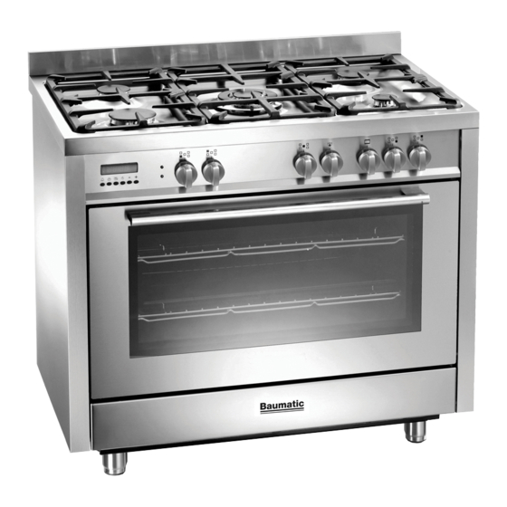
- Page 1 FREESTANDING DUAL FUEL COOKER DOMESTIC USE ONLY OPERATING AND INSTALLATION INSTRUCTIONS...
-
Page 2: Table Of Contents
The appliance was designed and made in accordance with the European standards listed below: => EN 30-1-1, EN 30-2-1 and EN 437 plus subsequent amendments (gas) => EN 60 335-1 and EN 60 335-2-6 (electrical) plus relative amendments The appliance complies with the prescriptions of the European Directives as below: =>... -
Page 3: Assistance And Spare Part
ASSISTANCE AND SPARE PARTS the best functioning results. Any subsequent repairs or adjustments that may be necessary must be done with the maximum of care and attention by authorised personnel. For this reason we recommend you always contact us (refer below), specifying the brand, model, serial number and type of problem you are having with it. -
Page 4: Important Notes And Precautions For Use
IMPORTANT NOTES AND PRECAUTIONS FOR USE You have purchased one of our products for which we There are a few basic rules that must be observed thank you. We are confident that this new appliance, when using the appliance: modern, functional and practical, made with top quality =>... -
Page 5: Description Of The Appliance
DESCRIPTION OF THE APPLIANCE PRESENTATION Our cooker is fitted with a fully gas hotplate. This innovative burner hotplate offers you more scope and � versatility in hotplate cooking than ever before. The round burners are graduated in their size and output �... - Page 6 DESCRIPTION OF THE APPLIANCE DESCRIPTION OF THE CONTROLS HOB GAS BURNER KNOB (A) By rotating the knob in an anticlockwise direction, the following symbols appear: = Closed position = “Full on” position = “Reduced rate or Low” position OVEN THERMOSTAT KNOB (B) By turning the oven knob clockwise we will find the different oven temperature values (from 50°C to Max).
- Page 7 DESCRIPTION OF THE APPLIANCE ELECTRONIC PROGRAMMER (F) � The programmer can select the following functions: - Clock (set by keys 2 and 3) � � � - Minute counter (set by key 1) � � - Cooking time (set by key 2) - End of cooking (set by key 3) - Manual operation mode...
-
Page 8: Instructions For The User
INSTRUCTIONS FOR THE USER the heat onto the hotplate (fig. 7) and surrounding HOB: GENERAL NOTES ON SAFETY surfaces. • When using the burners, do not leave the appliance • Use only a wok support supplied or recommended unsupervised. Ensure that children and the infirm by the manufacturer of the appliance (fig. - Page 9 INSTRUCTIONS FOR THE USER ����������� • When inserting or removing food from the oven, check that excess juices do not overflow onto the oven base (oils and fats are highly inflammable when overheated). • Use containers that will resist the temperatures indicated on the thermostat knob.
- Page 10 INSTRUCTIONS FOR THE USER HOW TO USE THE MULTIFUNCTION OVEN CONVETIONAL GRILL COOKING Turn the selector knob (C) to the symbol and adjust DEFROSTING AT ROOM TEMPERATURE the thermostat knob (B) to the desired temperature. Turn the selector knob (C) to the symbol and place the Selecting this function the top central heating element food you want to defrost inside the oven.
- Page 11 INSTRUCTIONS FOR THE USER USEFUL COOKING TIPS Meat: • If, when cooking meat, the time needed is more than 40 minutes, turn the oven off 10 minutes Cakes and bread: before the end of cooking time to exploit the • Heat the oven for at least 15 minutes before you residual heat (energy saving).
- Page 12 INSTRUCTIONS FOR THE USER COOKING / BAKING TIMETABLE COOKING BY COOKING BY Position of the NATURAL CONVECTION FORCED CONVECTION (WITH FAN) Weight FOODS oven shelf from the Temperature Cooking Time Temperature Cooking Time bottom in °C in minutes in °C in minutes MEAT Roast veal...
- Page 13 INSTRUCTIONS FOR THE USER the glass. NEVER use sponges or abrasive products, CLEANING AND MAINTENANCE and aromatic or aliphatic solvents to remove stains or • Prior to any maintenance work or cleaning, adhesives on the painted or stainless steel surfaces. disconnect the appliance from the electricity mains.
- Page 14 INSTRUCTIONS FOR THE USER OVEN DOOR REMOVAL The oven door can be removed to give easier access to the oven when cleaning. To remove, proceed as follows: • Open the oven door and move the release U-shape element (fig. A) forwards until it is over the tooth in the upper sector of the hinge (fig.
-
Page 15: Troubleshooting
TROUBLESHOOTING Some problems can be caused either as the results of simple maintenance operations or by incorrect selection of settings. Prior to contacting a Service Centre please check the following chart. PROBLEM REMEDY The appliance is not working • Make sure the gas cock is open •... -
Page 16: Instructions For The Installer
INSTRUCTIONS FOR THE INSTALLER TECHNICAL INFORMATION UNPACKING YOUR COOKER • Once the packaging has been removed, thoroughly The installations, conversions and maintenance check that the appliance is in perfect condition. If operations listed in this part must only be carried you have any doubts do not use the appliance and out by authorised personnel. - Page 17 INSTRUCTIONS FOR THE INSTALLER POSITION (fig. 12) The appliance should be positioned in good light and free from draughts. Any adjoining wall surface situated within 200 mm from the edge of any hob burner must be a suitable non-combustible material for a height of 150 mm for the entire length of the hob.
- Page 18 INSTRUCTIONS FOR THE INSTALLER SECURING THE COOKER TO WALL (fig. 16) Assembly instructions • Fix hook into wall immediately behind and to the Note:- The installation of the chain provided left-hand side about 770 mm from the floor. is for safety reasons, it must be installed as •...
- Page 19 INSTRUCTIONS FOR THE INSTALLER by means of a union connector. GAS CONNECTION • The gas connection and isolating tap must be This appliance shall be installed only by authorised accessible to a service person or inspector. personnel and in accordance with the manufacturer’s •...
- Page 20 INSTRUCTIONS FOR THE INSTALLER ELECTRICAL CONNECTION TAPS (fig. 20) All gas taps are male cone type with only one way of The electrical connection must be carried out in passage. The adjustment screw (V) is on the side of accordance with the current standards and laws the stem.
- Page 21 INSTRUCTIONS FOR THE INSTALLER GAS CONVERSIONS CHANGING THE FLEXIBLE GAS HOSE In order to guarantee that the gas hose is always in When converting from Natural Gas to Universal LPG excellent condition we strongly recommend changing ensure that the NG regulator is removed and replaced it on the date you will find printed on it.
- Page 22 INSTRUCTIONS FOR THE INSTALLER MAINTENANCE �� Prior to any maintenance work or changing parts, disconnect the appliance from the gas �� and electricity power sources. Servicing must only be carried out by authorised personnel. REPLACING THE TAPS Proceed in the following way when replacing a tap: •...
-
Page 23: Technical Features
TECHNICAL FEATURES � � BURNER DISPOSITION � � � BURNER TECHNICAL DATA TABLE OPERATING DIAMETER INJEC- BURNER By-pass RATING PRESSURE TORS DENOMINATION rating MJ/h MJ/h 1/100 mm Large Propane 2.75 10.0 Left front Natural 1.00 10.0 Medium Propane 2.75 Right rear Natural 1.00 Medium...