Table of Contents
Advertisement
Quick Links
Advertisement
Table of Contents

Related Manuals for Baumatic BAF90EG-2


Summary of Contents for Baumatic BAF90EG-2
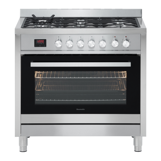
- Page 1 USER MANUA L 90CM FREESTANDING COOKER BAF90EG-2...
-
Page 2: Table Of Contents
Contents For your safety Safety of children and the infirm ......3 Cleaning and maintenance ......3 During use . -
Page 3: For Your Safety
For Your Safety We recommend that you read the instructions in this owner's manual carefully before use for the best performance and to extend the life of your appliance. It will provide you with all the information you need to ensure its safe installation, use and maintenance. -
Page 4: During Use
For Your Safety During use · The appliance becomes hot. Care should be taken to avoid touching heating elements inside the oven. · WARNING: Accessible parts will become hot when in use. To avoid burns and scalds, children should be kept away. ·... -
Page 5: Installation
For Your Safety During use (continued) · Use oven gloves to place cookware in the oven or when removing it. Always grip the oven door handle in the centre. · Glen Dimplex will not accept any liability as a result of any damage due to incorrect installation or improper use Installation ·... -
Page 6: Service And Spare Parts
For Your Safety Avoid the following: · Touching the appliance with wet parts of the body. · Using the appliance while barefoot. · Improper or dangerous operation. · Obstructing the ventilation or heat dissipation slots. · Allowing power supply cables of other appliances to come into contact with hot parts of the oven. -
Page 7: Use And Care
Use and Care Note: Material, colours, pan supports and burner configuration may vary i.e stainless steel / glass, wok burner position etc. -
Page 8: Oven & Accessories
Use and Care Oven & accessories The oven is supplied with chrome wire Shelf Supports and a range of shelf options as shown below. There are four shelf positions on the oven. Grill Tray with removable insert Oven Shelf Shelf Supports Oven Door... -
Page 9: Instructions For Use
Use and Care Instructions for use (cooktop burners) The symbols on the control knobs mean the following: No gas flow or 'Off' Maximum gas flow or 'high' flame and lighting position Minimum gas flow or 'low' flame All operating positions must be set between the maximum and minimum flow settings, and never between the maximum setting and the closed position. - Page 10 Use and Care To light the cooktop burners To light the burner, press the control knob fully down and hold the knob down before rotating anti-clockwise to the High Flame position. The ignition device is integrated into the control knob and is automatically activated by pushing down on the control knob.
-
Page 11: How To Use Your Oven
Use and Care How to use your oven This multi-function oven combines the advantages of traditional conventional ovens with modern fan forced ovens in a single appliance. It is an extremely versatile appliance that allows you to choose easily and safely between different cooking modes. The various cooking modes are selected by means of a cooking mode selection knob, located on the control panel. -
Page 12: Positioning The Oven Trays & Shelves
Use and Care Positioning the oven trays & shelves The Baking Tray, Grill Tray or Oven Shelf can be located in any of the five height positions. Refer to the ‘Cooking mode table’ for the recommended shelf position. When fitting the trays or shelves, ensure they are fitted between the two wires that are closest together as shown below. - Page 13 Use and Care COOKING MODES Conventional mode When set to Conventional mode, the top and bottom heating elements operate together like a ‘normal’ conventional oven that you have probably used before. Conventional mode is best suited for traditional baking and roasting and you should only use one shelf at a time, otherwise the heat distribution will be uneven.
- Page 14 Use and Care Fan assisted Top heat mode Select ‘Fan Assisted Top’ mode with cooking mode selection knob and turn cooking temperature selection knob to the desired temperature setting. When set to Fan Assisted Top mode, the top inner element and the fan operate. This mode increases the circulation of air throughout the oven, which helps prevent food from burning on the surface, allowing the heat to penetrate right into the food.
- Page 15 Use and Care Cooling ventilation In order to keep the appliance cool, this model is equipped with a cooling fan, which switches on automatically. When the cooling fan is on, you will notice a flow of air exiting between the oven door and the control panel.
- Page 16 Use and Care This model has a digital display, 24hr clock with 3 control buttons. When the power is connected, the screen displays ‘12:00’ and the bar above the symbol flashes. Setting the time when power is first connected To set the correct time, press the + or - button to advance forward or backward until the correct time is displayed.
- Page 17 Use and Care Automatic setting Automatic setting of the oven allows you to select the end time, cooking time, temperature and cooking mode. The oven will switch on, cook according to the selected cooking mode and temperature and then switch off automatically. 1.
- Page 18 Use and Care 1. Press the function button repeatedly until the bar above flashes, then press + or - button to set the time frame for cooking. 2. Set cooking temperature and cooking mode by turning the thermostat knob and selector knob. The oven starts immediately, the bar above will flash.
-
Page 19: Practical Cooking Advice
Use and Care This appliance will allow you to cook any type of food in the best possible way. With time you will learn to make the best use of this versatile cooking appliance. The following directions are only a guideline which may be varied according to your own personal experience. - Page 20 Use and Care Baking cakes When baking cakes ,always place them in a preheated oven. Make sure you wait until the oven has been preheated thoroughly (the indicator light will turn off). To prevent heat loss and the cake from dropping, do not open the oven door during baking.
- Page 21 Use and Care Cooking pizza For best results when cooking pizza: · Preheat the oven for at least 10 minutes. · Use a light aluminum pizza pan, placing it on the shelf supplied with the oven. Don’t use the dripping pan since this will extend the cooking time, making it difficult to get a crispy crust.
-
Page 22: Cleaning & Maintenance
Use and Care Cooktop cleaning and maintenance Before cleaning, make sure all burners are 'off' and allow the appliance to cool down. The enamelled or stainless steel parts should be washed with lukewarm water without using any abrasive powders or corrosive substances. - Page 23 Use and Care Oven cleaning and maintenance Before cleaning your oven or performing maintenance, make sure that the cooking mode selection knob and the cooking temperature selection knob is set to ‘OFF’. To extend the life of your oven, it must be cleaned frequently.
- Page 24 Proceed as follows: Remove and assemble procedure · Open door fully · Lift up and turn the small levers situated on the two hinges fully back · Grip the door on the two external sides; shut it slowly until door contacts the clips. Then continue closing door until it is about 10cm from closing fully.
- Page 25 Use and Care Routine maintenance Have the condition and efficiency of the gas pipe and the pressure regulator (if installed) checked periodically. If anomalies are found, do not repair components but have the faulty component replaced. To ensure good performance and safety, the gas regulator taps must be greased periodically.
-
Page 26: Disposal
Use and Care Replacing the oven lamps WARNING: Ensure that the appliance is switched off before replacing the lamp to avoid the possibility of electric shock. Remove the glass cover of the lamp-holder as shown below. Remove the lamp and replace with a lamp resistant to high temperatures (300°C) with the following characteristics: - Voltage: 220-240V - Wattage: 25W... -
Page 27: Technical Data
220-240V AC (50-60Hz) 220-240V ~ 50-60Hz... -
Page 28: Installation
Installation Instructions for installation This appliance shall be installed only by authorised persons and in accordance with the manufacturer's installation instructions, local gas fitting regulations, municipal building codes, electrical wiring regulations, AS/NZS 5601 - Gas Installations and any other statutory regulations. IMPORTANT: Installation, assembly and gas/electrical connections must be carried out by authorised personnel. -
Page 29: Dimensions
The Gas Inlet Connection is male 1/2" BSP and is located 65mm from the right or left and approx. *600mm from the floor. *May vary with adjustable legs. plus leveling feet (min 10mm) (When used for shelf installation) 130 - 195 AS/NZS 5601 Gas Installations Fig 5.1: Install Range Hoods in accordance with manufacturer's instructions, no closer than 600mm above the maintop for Range Hoods and... -
Page 30: Anti-Tilting Chains/Hose Restraining Chain
Installation Anti-tilting chains/hose restraining chain A chain should be fitted by the installer within 50mm of the hose connection point to prevent strain on the hose when the cooker is pulled forward. The chain should restrict the appliance movement to no more than 80% of the hose length. After the chain is installed, check that there is no strain on the hose or gas connections when the cooker is pulled as far forward as the chain allows. -
Page 31: Anti-Tilting Chain - Incorrect Installation
Installation Anti-tilting chains - INCORRECT Installation Accidental Tipping Chains are provided as a preventative measure against accidental tipping. These chains must be fitted as part of the installers compliance. Failure for your installer to fit chains in accordance with the relevant installation code will make the installation of your upright cooker non-compliant and class as an illegal installation. -
Page 32: Anti-Tilting Chain - Correct Installation
Installation Anti-tilting chains - CORRECT Installation In order to prevent the oven from tipping forward as shown on the previous page, we need to make sure both chains provided with the oven are used. LEFT SIDE RIGHT SIDE Hole and chain level On the left side of the oven, The right side has been... - Page 33 Installation Anti-tilting chains - CORRECT Installation Once the holes have been drilled, the chains can be fed through and the upright can be fitted into position. The chains then need to be pulled as tight as possible from inside the cabinet while at the same time being fixed to the rear of the cabinet using a self drilling wood screw.
-
Page 34: Connection To The Gas Supply
Installation Connection to the gas supply For ease of service, the cooker should be connected with a Flexible Hose, which complies with AS/NZS 1869 (Australian Approved),10mm ID, class B or D, between 1 - 1.2m long and in accordance with AS/NZS 5601 for a high level connection. WARNING: Ensure that the hose is not subjected to abrasion, kinking or permanent deformation and should be able to be inspected along its entire length. -
Page 35: Electrical Connection
Installation Electrical connection The appliance may be supplied fitted with a power cord and 15 amp 3 pin plug. Install the cooker so that the plug is easily accessible. Plug the 3-pin plug into a properly earthed, 15A general purpose power outlet. The supply cable should be positioned so that it does not reach a temperature of more than 75℃... -
Page 36: Gas Conversion
Gas Conversion (NG to U-LPG) Hob Burners Parts needed... - Test Point Assembly - ULPG Gas Type label - Auxiliary Jet Ø0.53mm - Semi-Rapid Jet Ø0.68mm - Rapid Jet Ø0.88mm - Wok Jet Ø1.00mm Converting to a different gas type When converting from Natural Gas to Universal LPG ensure that the NG regulator is removed and replaced with the Test Point Assembly supplied in the conversion kit. -
Page 37: U-Lpg To Ng
Gas Conversion (U-LPG to NG) Hob Burners Parts needed... - NG Regulator - NG Gas Type label - Auxiliary Jet Ø0.88mm - Semi-Rapid Jet Ø1.16mm - Rapid Jet Ø1.50mm - Wok Jet Ø1.75mm Converting to a different gas type When converting from Universal LPG to Natural Gas ensure that the ULPG test point is removed and replaced with the Australian Approved NG Regulator supplied in the conversion kit. -
Page 38: Warranty
Subject to the exclusions below, we warrant that the product will not have any electrical or mechanical breakdowns within: a) In the case of Baumatic products used for personal, domestic or household purposes, a period of 2 years from the date the product is purchased as a brand-new product from a... - Page 39 c) The repair relates to the replacement of consumable parts such as fuses and bulbs or any other parts of the product which require routine replacement; d) You are unable to provide us with reasonable proof of purchase for the product; e) the breakdown occurs after the expiry of the express warranty period set out in section 1 or f) the product was not purchased in Australia as a brand-new product.
- Page 40 5. Warranty claims If you make a valid claim under this warranty and none of the exclusions set out in section 2 apply, we will, at our election, either repair the product or replace the product with a product of identical specification (or where the product is superseded or no longer in stock, with a product of as close a specification as possible).
- Page 41 READ THE INSTRUCTION BOOKLET BEFORE INSTALLING AND USING THE APPLIANCE. The manufacturer will not be responsible for any damage to property or to persons caused by incorrect installation or improper use of the appliance. The manufacturer is not responsible for any inaccuracies, due to printing or transcription errors, contained in this manual.