Table of Contents
Advertisement
Advertisement
Table of Contents

Related Manuals for Baumatic BAU95EE


Summary of Contents for Baumatic BAU95EE
- Page 1 Instruction Manual Upright Cooker 90cm BAU95EE BAU95EG...
- Page 2 Customer Care team 1800 444 357 or email service@hapl.com.au We also carry a complete range of spare parts for all Baumatic products. For all your spare parts enquiries please contact our team at Pronto Parts on: 1300 306 973 Baumatic Australia is a division of Home Appliances PTY LTD...
- Page 3 Introducing your new cooker We thank you and congratulate you on your choice. These instructions cover two cooker models: BAU95EG and BAU95EE These carefully designed products, manufactured with the highest quality materials, have been corefully tested to satisfy all your cooking demands.
-
Page 4: Safety Considerations
Before connecting your new cooker Before using your new cooker, please read these 'Instructions for Use' carefully. They contain important information concerning your personal safety as well as on use and care of the oven. Please keep the operating and installation instructions in a safe place; this important documentation may also be of use to a possible subsequent owner. - Page 5 Electrical supply All three models require connection to a 15 Amp (BAU95EG) wall socket and Amp 50 (BAU95EE) circuit breacker. Instructions 1. The model number and the type of appliance, gas pressure and gas type ore found on A copy of the data plates is reproduced the inside of the oven door, centre bottom.
- Page 6 Height over hob: 910 mm Height over upstand: 980 mm Width: 895mm & handle Depth: (incl. oven door knobs): 660mm Depth: (flush with oven door): 610mm Gas and electric connection connection Electrical The electric lead and plug are for connection onto a 15 Amp socket. A 15 Amp socket is to be within 1 m of the appliance.The lead is situated at the left hand side of the cooker.
-
Page 7: Gas Connection
Gas connection The cooker must be connected to the gas supply with upstream connection of an isolation valve in accordance with the respectively valid requlations. We recommend that the isolation valve be fitted prior to the cooker to enable isolation of the cooker from the gas supply. -
Page 8: Test The Operation Of The Cooker Before Leaving
Test the operation of the cooker before leaving Note: These burners have no aeration adjustment Check correct operation of the ignitions system and operation of burners individually and in combination. Burner flames should be clear blue, with no yellow tipping. If the burners show any abnormality check that the burners are correctly located. - Page 9 If the legs are not used and the cooker is mounted onto a plinth, fit transit legs to allow for clearance. Once legs are adjusted to a nominai cooker height of 91 Omm, fit the antitilt restraint bracket. 1. Fit flat strap to rear of cooker at the centre point on lower edge using supplied screw 2.
- Page 10 fastener. 5. Locate the cooker into correct and final position. Then from the underside front, secure into position with self tapping screw provided. WARNING - IN ORDER TO PREVENT ACCIDENTAL TIPPING OF THE APPLIANCE, FOR EXAMPLE BY A CHILD CLIMBING ONTO THE OVEN DOOR, THE STABILISING MEANS MUST BE INSTALLED. REFER TO THE INSTRUCTIONS FOR INSTALLATION UPSTAND INSTALLATION BAU95EG ...
- Page 12 Voltage Type of cable cable section H05V V-F or H05RR-F 3x1,5 mm2 Operation at 240V~ H07RN-F or H05BB-F 3x1,5 mm2 BAU95EE Voltage Type of cable cable section H05V V-F or H05RR-F 3x6 mm2 Operation at 240V~ H07RN-F or H05BB-F 3x6 mm2 H05V V-F or H05RR-F 4x2.5 mm2...
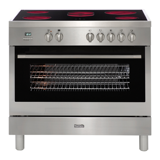
- Page 13 USING THE GLASS-CERAMIC HOB BAU95EE The working table has 5 cooking areas, which differ in power and diameter (Fig.8). Positions are clearly indicated with screen-printed round areas (see description of the hobs). The heating process comes inside these areas. When a worktop hotplate i s u sed fo r some time, th e rem aining surface rem ain hot; a red indicator in t he worktop surface light will indicate it.
- Page 14 Fig. 8 Fig. 9 Fig. 10 Fig.11 Fig. 12 Fig.13 Fig.14...
-
Page 15: Cooktop Burner Operation
Cooktop burner operation. For cookers fitted with the optional glass lid the glass lid must always be in the open position when the cooktop burners are operating. First time use Thoroughly clean cooktop with warm soapy water prior to first use. Cooktop burner operation The individual burner position on the cooktop is indicated by a graphic placed above the burner control knob. -
Page 16: Electronic Clock
Ventilation The use of gas burners leads to the production of heat and moisture in the kitchen. For this reason make sure that the room is properly ventilated. Keep ventilatin openings, such as windows, open or provide a mecnanical ventilation device (e.g. a range hood of overhead exhaust fan) Electronic clock To program the cooker press the desired function button and adjust the required time... -
Page 17: Manual Operation
Oven will not switch on/to clear a program If the oven will not switch on and the 'A' symbol is illuminated on the display, a program is stili running. To clear a program press the and the symbols simultaneously. The 'A' symbol will switch off and the only will be illuminated. - Page 18 1. Press the symbol and using the + and - buttons adjust the ti me you wish the cooking to stop 2. Turn the function selector control knob to the required mode. 3. Then turn thermostat control knob to the desired temperature. NOTE: the 'A' and the symbol should be illuminated.
-
Page 19: Oven /Grill Operation
Oven /grill operation Accessories 1 wire shelves 1 enamel baking tray Foods being grilled must be monitored at all times, especilally high fat content foods such as sausages, chops, ect. First time use Thoroughly clean the appliance and accessories with warm soapy water before using them for the first time. - Page 20 Switching the oven ON 1. Turn the function selector control to the required cooking mode. The orange 'power on' thermostat indicator light illuminates. 2. Set the temperature control to the required cooking temperature. The selected temperature will be maintained automatically. The orange thermostat indicator light illuminates when the oven is first turned on, and extinguishes when the required temperature is reached.
-
Page 21: Conventional Cooking
Conventional cooking Thermostat setting from 50°C – 250°C. Moderate oven 180°C. This mode uses upper and lower heating elements to cook. Cooking is possible on one shelf position only and food should be placed towards the centre of the oven on shelf position 3. -
Page 22: Oven Cooking Tips
Fan forced cooking Thermostat setting from 50°C - 250°C. Moderate oven 170°C. In this mode the rear circular heating element provides heat whilst the fan distributes the heat evenly throughout the oven interior. It is possible to cook several dishes simultaneously on different shelves and food can be placed on any shelf position. -
Page 23: Troubleshooting Guide
Trouble shooting guide Problem Possible cause Action Burners does not light Power to appliance turned off Turn on power supply Cooktop burner difficult to light Dry and reposition cap Burner damp incorrectly positioned Spark ignitor clogged with grease Clean ignitor Burner ports blocked Clean ports Spark igniter does not function... - Page 24 Cleaning Cleaning hob Once the appliance is cold, clean it with a sponge and soapy water. Remove any spills immediately. This will avoid unnecessary effort later Allow burners and trivets to cool down before cleaning them. The burners and trivets must be cleaned regularly to keep them in good condition. This is done by submerging them in soapy water and scrubbing them with a non-metal brush to keep the ports and slots free from obstructions so they give a perfect flame.
-
Page 25: Replacing The Oven Light Bulb
Cleaning oven glass door The oven door may be removed for cleaning. To remove the oven door follow the steps below: 1. Open the door fully 2. Lift the two levers forward as shown in figure below left 3. Close the door as far as the first stop (created by the raised levers). 4. -
Page 26: Service Information
Service information Service and maintenance must only be carried out by an authorised person This appliance shall not be modified. Always disconnect the gas supply and power before servicing the cooker. After service always check connections for gas soundness at connections with soapy water. - Page 27 Wiring diagrams BAU95EE A copy of those diagrams is situated on the back panel of the cooker.
- Page 28 Wiring diagrams BAU95EG A copy of those diagrams is situated on the back panel of the cooker.