
Related Manuals for Baumatic BAU91EG


Summary of Contents for Baumatic BAU91EG
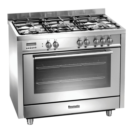
- Page 1 FREESTANDING DUAL FUEL COOKER DOMESTIC USE ONLY OPERATING AND INSTALLATION INSTRUCTIONS Models: BAU91EG -- BAU91EE...
-
Page 2: Table Of Contents
The appliance was designed and made in accordance with the European standards listed below: => EN 30-1-1, EN 30-2-1 and EN 437 plus subsequent amendments (gas) => EN 60 335-1 and EN 60 335-2-6 (electrical) plus relative amendments The appliance complies with the prescriptions of the European Directives as below: =>... -
Page 3: Assistance And Spare Part
ASSISTANCE AND SPARE PARTS the best functioning results. Any subsequent repairs or adjustments that may be necessary must be done with the maximum of care and attention by authorised personnel. For this reason we recommend you always contact us (refer below), specifying the brand, model, serial number and type of problem you are having with it. -
Page 4: Important Notes And Precautions For Use
IMPORTANT NOTES AND PRECAUTIONS FOR USE You have purchased one of our products for which we There are a few basic rules that must be observed thank you. We are confident that this new appliance, when using the appliance: modern, functional and practical, made with top quality =>... -
Page 5: Description Of The Appliance
DESCRIPTION OF THE APPLIANCE GENERAL There are 2 different hobs that can be used on our cookers: all gas and all electrical (with heating � elements in ceramic glass). Each knob on the front panel has a diagram printed � above it showing to which burner it refers. - Page 6 DESCRIPTION OF THE APPLIANCE DESCRIPTION OF THE CONTROLS HOB GAS BURNER KNOB (A) By rotating the knob in an anticlockwise direction, the following symbols appear: = Closed position = “Full on” position = “Reduced rate or Low” position OVEN THERMOSTAT KNOB (B) By turning the oven knob clockwise we will find the different oven temperature values (from 50°C to Max).
- Page 7 DESCRIPTION OF THE APPLIANCE ELECTRONIC PROGRAMMER (F) � The programmer can select the following functions: - Clock (set by keys 2 and 3) � � � - Minute counter (set by key 1) � � - Cooking time (set by key 2) - End of cooking (set by key 3) - Manual operation mode...
-
Page 8: Instructions For The User
INSTRUCTIONS FOR THE USER HOB: GENERAL NOTES ON SAFETY ABNORMAL OPERATION Any of the following are considered to be abnormal • When using the burners, do not leave the appliance operation and may require servicing: unsupervised. Ensure that children and the infirm •... - Page 9 INSTRUCTIONS FOR THE USER SWITCHING THE HEATING ELEMENTS The cooking zones are clearly visible on the hob, being circular. Only the inside of the circles traced on the glass is � heated. The hob has a built-in warning light that switches on when the temperature in the cooking zone exceeds 60°C.
- Page 10 INSTRUCTIONS FOR THE USER N.B.: Using the glass scraper, push immediately away GENERAL INFORMATION AND INSTRUCTIONS from the cooking zone, any pieces of tin foil or plastic FOR USING CERAMIC GLASS HOBS objects that could have melted or stuck; likewise •...
- Page 11 INSTRUCTIONS FOR THE USER indicated on the thermostat knob. OVEN: GENERAL SAFETY INSTRUCTIONS • Never cover the base of the oven or the oven shelf • Do not leave the oven unsupervised during use. with aluminium foil or other materials, as this creates Ensure that children and the infirm do not play with a fire hazard.
- Page 12 INSTRUCTIONS FOR THE USER HOW TO USE THE MULTIFUNCTION OVEN CONVETIONAL GRILL COOKING Turn the selector knob (C) to the symbol and adjust DEFROSTING AT ROOM TEMPERATURE the thermostat knob (B) to the desired temperature. Turn the selector knob (C) to the symbol and place the Selecting this function the top central heating element food you want to defrost inside the oven.
- Page 13 INSTRUCTIONS FOR THE USER USEFUL COOKING TIPS Meat: • If, when cooking meat, the time needed is more than 40 minutes, turn the oven off 10 minutes Cakes and bread: before the end of cooking time to exploit the • Heat the oven for at least 15 minutes before you residual heat (energy saving).
- Page 14 INSTRUCTIONS FOR THE USER COOKING / BAKING TIMETABLE COOKING BY COOKING BY Position of the NATURAL CONVECTION FORCED CONVECTION (WITH FAN) Weight FOODS oven shelf from the Temperature Cooking Time Temperature Cooking Time bottom in °C in minutes in °C in minutes MEAT Roast veal...
- Page 15 INSTRUCTIONS FOR THE USER NEVER use sponges or abrasive products, and CLEANING AND MAINTENANCE aromatic or aliphatic solvents to remove stains or adhesives on the painted or stainless steel surfaces. • Prior to any maintenance work or cleaning, disconnect the appliance from the electricity CERAMIC GLASS HOB mains.
- Page 16 INSTRUCTIONS FOR THE USER OVEN DOOR REMOVAL The oven door can be removed to give easier access to the oven when cleaning. To remove, proceed as follows: • Open the oven door and move the release U-shape element (fig. A) forwards until it is over the tooth in the upper sector of the hinge (fig.
-
Page 17: Instructions For The Installer
INSTRUCTIONS FOR THE INSTALLER TECHNICAL INFORMATION VENTILATION All rooms require an openable window or equivalent, The installations, conversions and maintenance while some rooms require a permanent vent in addition operations listed in this part must only be carried to the openable window. out by authorised personnel. - Page 18 INSTRUCTIONS FOR THE INSTALLER POSITION (fig. 13) The appliance should be positioned in good light and free from draughts. Any adjoining wall surface situated within 200 mm from the edge of any hob burner must be a suitable non-combustible material for a height of 150 mm for the entire length of the hob.
-
Page 19: Assembly Instructions
INSTRUCTIONS FOR THE INSTALLER SECURING THE COOKER TO WALL (fig. 16) Assembly instructions Secure threaded pins into wall immediately behind • Note:- The installation of the chain provided and to the left-hand side about 770 mm from the is for safety reasons, it must be installed as floor. - Page 20 INSTRUCTIONS FOR THE INSTALLER by means of a union connector. GAS CONNECTION • The gas connection and isolating tap must be This appliance shall be installed only by authorised accessible to a service person or inspector. personnel and in accordance with the manufacturer’s •...
- Page 21 INSTRUCTIONS FOR THE INSTALLER ADJUSTMENTS GAS CONVERSIONS REPLACING THE INJECTORS • Always disconnect the appliance from Our burners can be adapted to different types of gas by the electricity supply before making any simply installing the injectors suitable for the gas you adjustment.
- Page 22 INSTRUCTIONS FOR THE INSTALLER MAINTENANCE Prior to any maintenance work or changing parts, disconnect the appliance from the gas and electricity power sources. Servicing must only be carried out by authorised personnel. �� REPLACING THE TAPS Proceed in the following way when replacing a tap: •...
-
Page 23: Technical Features
2.75 14.6 Center Natural 1.00 15.0 ELECTRICAL COMPONENTS NOMINAL DATA DESCRIPTION BAU91EG BAU91EE Lower heating element of the oven 2100 W 2100 W Top heating element of the oven-grill 2000 + 2200 W 2000 + 2200 W Rear heating element... - Page 24 SPACE FOR DATA LABEL...