Panasonic KX-TD816 Installation Manual
Digital super hybrid system
Hide thumbs
Also See for KX-TD816:
- Installation manual (502 pages) ,
- Programming manual (443 pages) ,
- User manual (388 pages)
Table of Contents
Advertisement
Digital Super Hybrid System
MODEL
KX-TD816/KX-TD816B
KX-TD1232/KX-TD1232B
KX-TD1232D/KX-TD1232DB
Please read this manual before connecting the
Digital Super Hybrid System.
Attachment of customer owned equipment is illegal in
some areas of Canada.
Please consult with your Telephone Company.
KX-TD816
KX-TD1232
Advertisement
Table of Contents
Troubleshooting

Related Manuals for Panasonic KX-TD816


Summary of Contents for Panasonic KX-TD816
- Page 1 Digital Super Hybrid System Please read this manual before connecting the Digital Super Hybrid System. Attachment of customer owned equipment is illegal in some areas of Canada. Please consult with your Telephone Company. MODEL KX-TD816/KX-TD816B KX-TD816 KX-TD1232 KX-TD1232/KX-TD1232B KX-TD1232D/KX-TD1232DB...
-
Page 2: System Components
KX-A216* Backup Battery and Adaptor Card System Components Table The KX-TD816 and KX-TD816B are described as KX-TD816 in this Installation Manual hereafter except necessary cases. Also, the KX-TD1232, KX-TD1232B, KX-TD1232D, and KX-TD1232DB are described as KX-TD1232 except necessary cases. The models marked * can be installed in KX-TD1232 only. - Page 3 • In this Installation Manual, the expansion unit KX-TD170D/KX-TD180D are all described as KX-TD170/KX-TD180 except necessary cases. • There are some features and models available for certain types of KX-TD816 or KX-TD1232 models. In that case, those manual describes each time what is...
- Page 4 Precaution • Keep the unit away from heating appliances and electrical noise generating devices such as fluorescent lamps, motors and television. These noise sources can interfere with the performance of the Digital Super Hybrid System. • This unit should be kept free of dust, moisture, high temperature (more than 40˚C / 104˚F) and vibration, and should not be exposed to direct sunlight.
- Page 5 Introduction This Installation Manual provides technical information for the Panasonic Digital Super Hybrid System, KX-TD816/KX-TD1232. It is designed to serve as an overall technical reference for the system and includes a description of the system, its hardware and software, features and services and environmental requirements.
- Page 6 Information There are some features and items unavailable for certain KX-TD816/KX-TD1232 models. The table below shows what features/items are unavailable for which models and in which sections they are described. Model Number of Unavailable Related Section Main Unit Feature/Item KX-TD816C Panasonic Clip Section 2.3.4...
- Page 7 Information Model Number of Unavailable Related Section Main Unit Feature/Item KX-TD816NL Calling Party Control Section 3 KX-TD1232NL (CPC) Signal “Calling Party Control (CPC) Detection Signal Detection” Section 4.6 [405] “CPC Signal Detection Incoming Set” [415] “CPC Signal Detection Outgoing Set” Pulse to Tone Section 3 Conversion...
-
Page 8: Table Of Contents
Digital Proprietary Telephone and a Single Line Telephone .... 2.3.7 Polarity Sensitive Telephone Connection ....... 2-33 2.3.8 External Pager (Paging Equipment) Connection ....2-34 2.3.9 External Music Source Connection......... 2-36 : Available for KX-TD1232 only. : Available for KX-TD816C/1232C and KX-TD816HK/1232HK only. : Available for KX-TD816 only. - Page 9 Button, Single-CO (S-CO) ..............3-18 Buttons on Proprietary Telephones............. 3-19 CALL FORWARDING FEATURES – SUMMARY ......3-21 Call Forwarding – All Calls ............... 3-21 : Available for KX-TD1232 only. : Available for KX-TD816C/1232C and KX-TD816HK/1232HK only. : Available for KX-TD816 only.
- Page 10 Contents Call Forwarding – Busy..............3-22 Call Forwarding – Busy / No Answer ..........3-23 Call Forwarding – Follow Me ............3-24 Call Forwarding – No Answer............3-24 Call Forwarding – to CO Line............3-25 Call Hold – CO Line................3-26 Call Hold –...
- Page 11 Contents Display, Call Information ..............3-52 Display, Extension Programmed Data..........3-53 Display, Self-Extension Number ............3-54 Display, Time and Date ..............3-54 Display Contrast Adjustment ............. 3-55 Do Not Disturb (DND) ............... 3-55 Do Not Disturb (DND) Override............3-56 Door Opener ..................3-56 Doorphone Call ..................
- Page 12 Contents Lockout....................3-81 Loop-CO (L-CO) Button → Button, Loop-CO (L-CO)..... 3-17 Manager Extension ................3-82 Message Waiting................. 3-82 Microphone Mute ................3-83 Mixed Station Capacities..............3-83 Module Expansion................3-84 Music on Hold ..................3-85 Night Service ..................3-85 Off-Hook Call Announcement (OHCA) ..........3-86 One-Touch Dialing ................
- Page 13 Contents Single-CO (S-CO) Button → Button, Single-CO (S-CO) ....3-18 Special Features for KX-T7235............3-104 Call Log ......................3-104 Extension Dialing ..................3-104 Station Speed Dialing ................... 3-105 System Feature Access Menu............... 3-105 System Speed Dialing................... 3-106 Station Feature Clear ................3-106 Station Hunting...................
- Page 14 Contents [003] Extension Number Set............. 4-19 [004] Extension Name Set ..............4-21 [005] Flexible CO Button Assignment ..........4-23 [006] Operator / Manager Extension Assignment ......4-25 [007] DSS Console Port and Paired Telephone Assignment .... 4-26 [008] Absent Messages ..............4-28 System Programming ...............
- Page 15 Contents [301]–[305] TRS Denied Code Entry for Levels 2 through 6... 4-67 [306]–[310] TRS Excepted Code Entry for Levels 2 through 6..4-68 [311] Special Carrier Access Codes ..........4-69 [312] ARS Mode................4-70 [313] ARS Time................4-71 [314]–[321] ARS Leading Digit Entry for Plans 1 through 8 ... 4-72 [322]–[329] ARS Routing Plans 1 through 8 ........
- Page 16 Contents [607]–[608] Doorphone Ringing Assignment — Day / Night ..4-108 [609] Voice Mail Access Codes ............4-110 Resource Programming..............4-111 [800] SMDR Incoming / Outgoing Call Log Printout ...... 4-111 [801] SMDR Format ................. 4-112 [802] System Data Printout............... 4-113 [803] Music Source Use..............
-
Page 17: Section 1, System Outline
Section 1 System Outline This section provides general information on the system, including system capacity and specifications. -
Page 18: System Highlights
Expansion modules are used to increase the system capacity. One CO line module can be added to the basic system to add four CO lines. For KX-TD816, one extension module can be added to the basic system to add 8 extensions, and for KX-TD1232, two extension modules to add 16 extensions. - Page 19 The system can be programmed from a proprietary telephone or from a personal computer. Voice Mail Integration The system supports Voice Processing Systems with in-band DTMF signaling. The Panasonic Voice Processing System provides automated attendant, voice mail, interview and bulletin board services. Automatic Route Selection (ARS) Automatically selects the pre-programmed least expensive route for outgoing toll calls.
-
Page 20: Basic System Construction
Basic System Construction The KX-TD816 Digital Super Hybrid System has a basic capacity of four CO lines and eight extensions, and KX-TD1232 has eight CO lines and 16 extensions. It is capable of supporting Panasonic digital and analog proprietary telephones, DSS Consoles and single line devices such as single line telephones, facsimiles. -
Page 21: Proprietary Telephones
Proprietary Telephones The following Panasonic proprietary telephones are available with this system. Proprietary Description Telephone KX-T7220 Digital, speakerphone, 24 CO KX-T7230 Digital, display, speakerphone, 24 CO KX-T7235 Digital, large display, speakerphone, 12 CO KX-T7250 Digital, monitor, 6 CO KX-T7130 Display, speakerphone, 12 CO, 12 PF... -
Page 22: Options
1.4.2 4-CO Line Unit (KX-TD180) Adds four CO lines. One expansion unit can be added for a maximum of 8 CO lines for KX-TD816, and 12 CO lines per system for KX-TD1232. D816 D816 DIGITAL SUPER HYBRID SYSTEM... -
Page 23: Disa Card (Kx-Td191)
Options 1.4.4 DISA Card (KX-TD191)* This card is required to use the Direct Inward System Access (DISA) feature and to record an Outgoing Message. DISA allows you to access the desired destination in the system directly from an external telephone. Once you have accessed the DISA line, just dial the extension number. -
Page 24: Doorphone Card (Kx-Td160)
Opener 2 Opener 2 1.4.8 Backup Battery and Adaptor Card (KX-A216)* Operate all the features as a backup power supply in the event of a power failure. Backup Battery and Adaptor Card (KX-A216) System Outline *: Available for KX-TD816 only. -
Page 25: Battery Adaptor (Kx-A46)
Options 1.4.9 Battery Adaptor (KX-A46) × Supports the connection of two car batteries (12 VDC 2) for power backup in case of a power failure. Battery Adaptor KX-A46 Battery Adaptor KX-A46 Battery Adaptor KX-A46 Two car batteries, connected in series Two car batteries, connected in series Two car batteries, connected in series Battery Adaptor Connector... -
Page 26: Specifications
Specifications 1.5.1 General Description KX-TD816 System Capacity CO lines 8 max. Stations 16 max. (32 max. with eXtra Device Port) Control Method CPU: 16-bit CPU Switching Non Blocking PCM Time Sharing Switch Power Supplies Service Unit Primary Power KX-TD816BX 115 / 200 / 220 / 240 VAC, 50 / 60 Hz 220 –... - Page 27 Specifications Stations Connector Service Unit 4-pin Connector KX-TD816BX/HK/ML Modular Jack KX-TD816C/NL/NZ Paging Output Pin Jack (RCA JACK) External Music Input Two-conductors Jack {MINIJACK 3.5 mm (9/64 inch) diameter} Extension Connection Cable Single line telephones, KX-T7051, KX-T7052 1 pair wire (T, R) KX-T7220, KX-T7230, KX-T7235, KX-T7250 2 pair wire (D1, D2) or 2 pair wire (T, R, D1, D2)
- Page 28 Specifications assigned to stations (Power Failure Transfer) • System operation for about three hours using recommended batteries (consisting of two 12 VDC car batteries) Dialing Outward Dial Pulse (DP) 10 pps, 20 pps Tone (DTMF) Dialing Internal Dial Pulse (DP) 10 pps, 20 pps Tone (DTMF) Dialing Mode Conversion DP-DTMF, DTMF-DP...
-
Page 29: Characteristics
Specifications 1.5.2 Characteristics KX-TD816 Station Loop Limit KX-T7220/KX-T7230/KX-T7235/KX-T7250/KX-T7020/KX- T7030/KX-T7033/KX-T7050/KX-T7055/KX-T7130 ..40 ohms Single Line Telephone/KX-T7051/KX-T7052 .....600 ohms including set Doorphone..........20 ohms Minimum Leakage Resistance 15 000 ohms Maximum Number of Station Instruments per Line 1 for KX-T7220, KX-T7230, KX-T7235, KX-T7250, KX-T7130, KX-T7020, KX-T7030,... -
Page 30: 1.5.3 System Capacity
Hookswitch Flash Timing Range 84 – 1 000 milliseconds for KX-TD1232NL 204 – 1 000 milliseconds for the other systems 1.5.3 System Capacity Lines, Cards, Station Equipment KX-TD1232 Max. Quantity Item KX-TD816 Single System Max. Quantity System Connection *System Inter Connection Card —... - Page 31 Specifications 8-Station Line Unit 1 (8 extn.) 2 (16 extn.) 4 (32 extn.) Extension Jack Station Terminal (including DSS Consoles) {DSS Console} DISA Card — Caller ID Card Remote Card — Doorphone Card Doorphone Door Opener External Pager External Music Source System Data Item Max.
-
Page 33: 2.3.1 System Connection Diagram
2.3.1 System Connection Diagram KX-TD1232 Printer for SMDR or Personal Computer for System Programming Battery Adaptor KX-A46 Two car batteries, connected in series Consisting of two 12 VDC • To AC Outlet External Music Source 1 Amplifier Speaker External Music Source 2 Amplifier Speaker 2-14... - Page 34 2.3.1 System Connection Diagram KX-TD1232 12 CO Lines 16 extensions- additional) (one pair) Single Line Telephone KX-T7052 Cordless Phone Parallel connection of telephones is possible. Refer to Section 2.3.4 “Paralleled Telephone Connection.” Installation 2-15 : needs Optional Cards or Adaptor. Doorphone 1 Doorphone 2 Door Opener 1 Door Opener 2...
-
Page 35: 2.3.2 Co Line Connection
Connection Use 4-pin plugs (included) to connect CO lines. There are two plugs to connect four CO lines for KX-TD816, and four plugs to connect eight CO lines for KX-TD1232. A plug is able to connect two CO lines. Use twisted pair cable. - Page 36 2.3.2 CO Line Connection (KX-TD816: CO1 through CO4, KX-TD1232: CO1 through CO8) 2. Insert the plug into an CO jack in the main unit. KX-TD816 CO 4 CO 3 CO 2 CO 1 To Terminal Board or Modular Jacks from the Central Office...
- Page 37 2.3.2 CO Line Connection (KX-TD816: CO1 through CO4, KX-TD1232: CO1 through CO8) 2. Using Modular Connector (for KX-TD816C/NL/NZ, KX-TD1232BX/C/ HK/ML/NL/NZ/X) Connection Insert the modular plugs of the telephone line cords (4-conductor wiring) into the modular jacks on the system. R: Ring @ @ T: Tip...
-
Page 38: For Proprietary Telephones, Single Line Telephones And Dss Consoles
2.3.3 Extension Connection for Proprietary Telephones, Single Line Telephones and DSS Consoles (KX-TD816: Jack 1 through Jack 8, KX-TD1232: Jack 1 through Jack 16) There are four methods to perform Extension Connection, using a 4-pin connector, a 6-pin connector, a modular connector and an Amphenol Connector. - Page 39 2.3.3 Extension Connection for Proprietary Telephones, Single Line Telephones and DSS Consoles (KX-TD816: Jack 1 through Jack 8, KX-TD1232: Jack 1 through Jack 16) 1. Using 4-pin Connector (for KX-D816BX/HK/ML) Connection Use 4-pin plugs (included) to connect extensions. There are 8 plugs to connect extensions to jacks 1 through 8.
- Page 40 2.3.3 Extension Connection for Proprietary Telephones, Single Line Telephones and DSS Consoles (KX-TD816: Jack 1 through Jack 8, KX-TD1232: Jack 1 through Jack 16) 2. Using 6-pin Connector (for KX-TD1232DBX/DX) Wire Specification The wire specifications are as follows: Wire Solid wire ø0.4-ø0.65 mm (...
- Page 41 2.3.3 Extension Connection (Jack 01 through Jack 16) for Proprietary Telephones, Single Line Telephones and DSS Consoles (KX-TD816: Jack 1 through Jack 8, KX-TD1232: Jack 1 through Jack 16) 1. Using Modular Connector (for KX-TD816C/NL/NZ) Connection Insert the modular plugs of the telephone line cords (4-conductor wiring) into the modular jacks on the system.
- Page 42 2.3.3 Extension Connection (Jack 01 through Jack 16) for Proprietary Telephones, Single Line Telephones and DSS Consoles (KX-TD816: Jack 1 through Jack 8, KX-TD1232: Jack 1 through Jack 16) 2. Using Amphenol Connector (for KX-TD1232BX/C/HK/ML/NL/NZ/X) Connection To connect jacks 1 through 16, insert the connectors to the system as shown.
- Page 43 2.3.3 Extension Connection for Proprietary Telephones, Single Line Telephones and DSS Consoles (KX-TD816: Jack 1 through Jack 8, KX-TD1232: Jack 1 through Jack 16) Cable Pin Numbers to Be Connected EXTN. 9-16 CONN. CLIP EXTN. 1-8 8EXTN† 8EXTN† 8EXTN† Jack...
- Page 44 Proprietary Telephones, Single Line Telephones and DSS Consoles (KX-TD816: Jack 1 through Jack 8, KX-TD1232: Jack 1 through Jack 16) There are two expansion areas on the main unit of KX-TD816, one for 8-Station Line Unit and the other for 4-CO Line Unit.
- Page 45 2.3.3 Extension Connection for Proprietary Telephones, Single Line Telephones and DSS Consoles (KX-TD816: Jack 1 through Jack 8, KX-TD1232: Jack 1 through Jack 16) Connection of Proprietary Telephones, Single Line Telephones and DSS Consoles for KX-TD1232 Connection of the Proprietary Telephone, KX-T7130 6-conductor wiring is required for each extension.
- Page 46 2.3.3 Extension Connection for Proprietary Telephones, Single Line Telephones and DSS Consoles Notes • Up to four DSS Consoles (KX-T7040 or KX-T7240) can be installed per system. As the DSS Console itself cannot work alone, it always requires a proprietary telephone used in pair. Place the DSS Console and the paired telephone side by side on your desk.
-
Page 47: Optional Extension Connection Of Kx-A205 (Clip Terminal)
2.3.4 Optional Extension Connection of KX-A205 (Clip Terminal)* If you use the Clip Terminal, KX-A205 to connect eight extensions, connect a cable shown below to the clip terminal as follows. Refer to “Connection Chart” on the following page. Clip no. Connector type Pin no. - Page 48 2.3.4 Optional Extension Connection of KX-A205 (Clip Terminal)* Connection Chart This chart is used for the Panasonic cable KX-A204 only. Cable Clip Number Jack Cable Clip Number Jack Color of Dot Color of Dot orange-red orange-red orange-black orange-black yellow-red 1, 9, 17...
-
Page 49: 2.3.5 Paralleled Telephone Connection
Any single line telephone can be connected in parallel with a proprietary telephone as follows: Method 1: Using a Modular T-Adaptor Modular T-Adaptor (Panasonic KX-J66 or USOC RJA2X) 2-conductor wiring cord Connect pins “T” and “R”. 4-conductor wiring cord For DPT: Connect pins “D1” and “D2”... - Page 50 2.3.5 Paralleled Telephone Connection for a Proprietary Telephone and a Single Line Telephone Method 2: for Digital Proprietary Telephone only 4-conductor wiring cord 2-conductor wiring cord Connect pins “T”, “R”, “D1” Connect pins “T” and “R”. and “D2”. Rear of the telephone To main unit To Single Line (“TO EMSS”...
-
Page 51: 2.3.6 Extra Device Port (Xdp) Connection
2.3.6 EXtra Device Port (XDP) Connection for a Digital Proprietary Telephone and a Single Line Telephone A digital proprietary telephone (KX-T7220, KX-T7230, KX- T7235, or KX-T7250) and a single line telephone can be connected to the same extension jack yet have different extension numbers (eXtra Device Port feature). -
Page 52: Polarity Sensitive Telephone Connection
Extensions (T, R) of jacks 17 and 18 (Extension Expansion Card 1)•••CO 9 and CO 10 (Note: Extensions of jacks 9 and 10 for KX-TD816, and 17 and 18 for KX-TD1232 depend on the Power Failure Transfer connection. For details, refer to Section 2.5 “Auxiliary Connection for Power... -
Page 53: External Pager (Paging Equipment) Connection
2.3.8 External Pager (Paging Equipment) Connection KX-TD816 One external pager (user-supplied) can be connected to KX-TD816 as illustrated below. Use an RCA connector and shielded cable. • Output impedance: 600 Ω Maximum length of the cable Paging Jack AWG 18 – 22: Under 10 m (33 feet) - Page 54 2.3.8 External Pager (Paging Equipment) Connection Notes • System Connection* permits a maximum of four external pagers. It is programmable which external pager will send background music and whether all the pagers will generate confirmation tone. • To adjust the sound level of the pagers, use the volume control on the amplifiers.
-
Page 55: 2.3.9 External Music Source Connection
2.3.9 External Music Source Connection KX-TD816 One music source such as a radio (user-supplied) can be connected to KX-TD816 as illustrated below. Insert the plug to the earphone / headphone jack on the external music source. External Music Jack Use a two-conductor plug {3.5 mm (9/64 inch) in diameter}. - Page 56 2.3.9 External Music Source Connection Notes • System Programming of music sources used for Music on Hold and Background Music is required. • To adjust the sound level of the Music on Hold, use the volume control on the external music source. •...
- Page 57 Section 2 Installation This section contains the basic system installation and wiring instructions, as well as how to install the optional cards and units.
- Page 58 Before Installation Please read the following notes concerning installation and connection before installing the system. Safety Installation Instructions When installing telephone wiring, basic safety precautions should always be followed to reduce the risk of fire, electric shock and injury to persons, including the following: 1.
- Page 59 Power Switch of the system and then on again. 8. The KX-TD816/KX-TD1232 is equipped with a 3-wire grounding type plug. This is a safety feature. If you are unable to insert the plug into the outlet, contact your electrician to replace your obsolete outlet.
- Page 60 Installation of the Main Unit 2.2.1 Unpacking Unpack the box and check the items below: KX-TD816 KX-TD1232 Main Unit AC Cord Templet Screw three four three four Anchor Plug — Pager Connector — Music Source Connector Expansion line cord holder Plug Adaptor* —...
- Page 61 Installation of the Main Unit Inside View of the Main Unit KX-TD816 (4-pin Connector Type) Extension Modular Jacks CO Modular Jacks Fuse Front Cover KX-TD816 (Modular Connector Type) Extension Modular Jacks CO Modular Jacks Installation...
- Page 62 Installation of the Main Unit CO 4-pin Jacks KX-TD1232 (4-pin/6-pin Connector Type) Extension 6-pin jacks REMOTE SYSTEM INTER CONNECTION Paging Jack 2 Paging Jack 1 External Music Jack 2 External Music Jack 1 DISA System Clear Switch Reset Button DOORPHONE Front Cover KX-TD1232 (Modular/Amphenol Connector Type)
- Page 63 Installation of the Main Unit Power Supply for KX-TD816 Check the Voltage Selector to confirm if it is set to your house hold AC voltage. If not, reset the Voltage Selector on the back of the main unit to the correct position with a screwdriver.
- Page 64 If screws other than the ones supplied are used, use the same-sized diameter screws as the enclosed ones. KX-TD816 Mounting on Wooden Wall Mounting on Concrete or Mortar Wall 1.
- Page 65 2.2.3 Wall Mounting KX-TD1232 Mounting on Wooden Wall Mounting on Concrete or Mortar Wall 1. Place the templet (included) on the wall 1. Place the templet (included) on the wall to mark the four screw positions. to mark the four screw positions. 2.
- Page 66 Installation of the Main Unit 2.2.4 Frame Ground Connection IMPORTANT!!! Connect the frame of the main unit to ground. To ground To ground 2-10 Installation...
- Page 67 Installation of the Main Unit 2.2.5 Opening Front Cover 1. Loosen two screws on the right side of the main unit. 2. Open the front cover in the direction of arrow screw screw screw screw Note Two screws are attached to the front cover with springs so that they will not be lost.
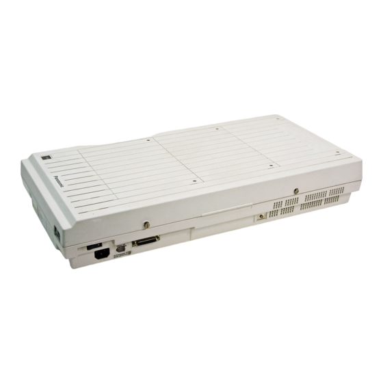
- Page 68 Connection 2.3.1 System Connection Diagram KX-TD816 External Music Source Amplifier Speaker Printer for SMDR or Personal Computer for System Programming Battery Adaptor KX-A46 Two car batteries, connected in series Consisting of two 12 VDC • To AC Outlet 2-12 Installation...
- Page 69 2.3.1 System Connection Diagram KX-TD816 (CO Lightning Protectors) to CO’s 1 through 4 (initial) D816 DEGITAL SUPER HYBRID SYSTEM to CO’s 5 through 8 (additional) 8 CO Lines Doorphone KX-T30865 Doorphone 2 Door Opener 1 Door Opener 2 Doorphone 1...
-
Page 70: 2.3.10 Printer Connection
2.3.10 Printer Connection A user-supplied printer can be connected to the EIA (RS-232C) Connector (25-pin) on the main unit. The printer is used to print out SMDR call records and system programming data. Connect the EIA (RS-232C) connector of the printer to the EIA Connector. - Page 71 2.3.10 Printer Connection Connection Chart for Printer / Personal Computer (25-pin) If you connect a PC or the printer with 25-pin EIA (RS-232C) connector to your system, see the chart below. EIA (RS-232C) port on EIA (RS-232C) port on the printer/PC (25-pin) the main unit (25-pin) Circuit Circuit...
- Page 72 2.3.10 Printer Connection EIA (RS-232C) Signals Frame Ground: FG Connects to the unit frame and the earth ground conductor of the AC power cord. Transmitted Data: SD (TXD) ..........(output) Conveys signals from the unit to the printer. A “Mark” condition is held unless data or BREAK signals are being transmitted.
-
Page 73: 2.3.11 Installation Of Lightning Protectors
Lightning Protector KX-TD816C • TELESPIKE BLOK MODEL TSB (TRIPPE MFG. KX-TD1232C CO.) • SPIKE BLOK MODEL SK6-0 (TRIPPE MFG. CO.) • Super MAX™ (PANAMAX) • MP1 (1TW LINX) Other Models Panasonic KX-A207 Installation Lightning Protectors Terminal Main Unit Board EXTN EXTN... - Page 74 2.3.11 Installation of Lightning Protectors Outside Installation (Main Building) Protectors (Another Building) Ter- Main EXTN minal Unit Board Lightning EXTN Protector EXTN EXTN Ground Notice If you install an extension outside of the main building, the following precautions are recommended: (1) Install the extension wire underground.
- Page 75 2.3.11 Installation of Lightning Protectors Installation of an Earth Rod Lightning Protector Grounding Wire Main Unit (Underground) Earth Rod 1) Installation location of the earth rod .....Near the protector 2) Check obstructions........None 3) Composition of the earth rod ......Metal 4) Depth of the earth rod ........More than 50 cm (20 inches) 5) Size of the grounding wire......Thickness is more than 16 AWG...
- Page 76 2.3.11 Installation of Lightning Protectors Installation of the KX-A207 1. Secure the protector to a building with the enclosed mounting screws. 2. Remove about 1 cm (13/32 inch) of insulation from the end of the earth wire. Insert the earth wire through the bottom of the protector base and secure it to the earth terminal.
-
Page 77: Installation Of Optional Cards And Units
Installation of Optional Cards and Units 2.4.1 Location of Optional Cards and Units The location of the optional cards is shown below. Precaution To protect the printed circuit boards (P-boards) from static electricity, do not touch parts on the P-boards in the main unit and on the optional cards. Expansion Units KX-TWP816 One 4-CO Line Unit (KX-TD180) and / or one 8-Station Line Unit... -
Page 78: 2.4.1 Location Of Optional Cards And Units
2.4.1 Location of Optional Cards and Units KX-TD1232 One 4-CO Line Unit (KX-TD180) and/or up to two 8-Station Line Units (KX-TD170) can be installed to any of the three expansion areas. 8EXT 8-Station DIGITAL SUPER HYBRID SYSTEM Line Units, KX-TD170: Expansion Each unit area 3... - Page 79 2.4.1 Location of Optional Cards and Units Backup Battery and Adaptor Card, Doorphone Card for KX-TWP816 Install Backup Battery and Adaptor Card, KX-A216. Doorphone Operates all the features in the event of a Card power failure. Connector Install Doorphone Card, KX-TD160. Backup This card connects two doorphones and two Battery...
-
Page 80: Location Of Optional Cards
2.4.1 Location of Optional Cards Caller ID Cards* Up to two Caller ID Cards (KX-TD193) for KX-TD816, and up to three Caller ID Cards for KX-TD1232 can be installed to the initially provided CO Line Card and 4-CO Line Unit. This card supports Caller ID services offered by the central office. -
Page 81: 2.4.2 4-Co Line Unit Connection
2.4.2 4-CO Line Unit Connection To add four CO lines (CO 5 through CO 8 for KX-TD816, and CO 9 through CO 12 for KX-TD1232), use the optional 4-CO Line Unit (KX-TD180). This unit can be installed to any of the expansion unit areas provided on the front of the main unit. -
Page 82: Installing Expansion Unit (Kx-Td170 / Kx-Td180)
2.4.4 Installing Expansion Unit (KX-TD170 / KX-TD180) KX-TD816 The following procedures can be used to install either 8-Station Line Unit (KX-TD170) or 4-CO Line Unit (KX-TD180) for KX- TD816. The model numbers of the main units and expansion units to be used are shown below. - Page 83 2.4.4 Installing Expansion Unit (KX-TD170 / KX-TD180) 5. Connect the frame of the expansion unit to the ground. Secure the inside screw to fix the cabinet to the main unit. D816 D816 DIGITAL SUPER HYBRID SYSTEM To ground To ground Note If two expansion units are installed, frame ground connection is required for only one unit.
- Page 84 2.4.4 Installing Expansion Unit (KX-TD170 / KX-TD180) If KX-TD180 is to be installed; (for KX-TD816C/NL/NZ) Insert the modular plugs of the telephone line cords (4-conductor wiring) into the modular jacks on the unit. (T1/R1)(T2/R2) CO 5, CO 6 CO 7, CO 8 T2 R1 T1 R2 R: Ring T: Tip...
- Page 85 2.4.4 Installing Expansion Unit (KX-TD170 / KX-TD180) If KX-TD170 is to be installed; (for KX-TD816C/NL/NZ) Insert the connector into the jack. Jack for Power Failure Transfer † Connector type Connector type 50-pin (Amphenol 57JE series or the equivalent) To extensions (Jacks 9 –...
- Page 86 2.4.4 Installing Expansion Unit (KX-TD170 / KX-TD180) Notes • If two expansion units are installed, cut • If you attach the Caller ID Card, KX- the cabinet cover(s) on the lower TD193 to the 4-CO Line Unit, KX- cabinet(s) to let the cords from upper TD180, attach it before installing the 4- cabinet go down through the cabinet CO Line Unit to the main unit.
- Page 87 2.4.4 Installing Expansion Unit (KX-TD170 / KX-TD180) KX-TD1232 The following procedures can be used to install either 8-Station Line Unit (KX-TD170) or 4-CO Line Unit (KX-TD180) for KX- TD1232. The KX-TD170D and the KX-TD180D are available for the KX-TD1232DBX/X only. The model numbers of the main units and expansion units to be used are shown below.
- Page 88 2.4.4 Installing Expansion Unit (KX-TD170 / KX-TD180) 5. Connect the frame of the expansion unit 3. Hook the cabinet on the main unit and to ground. Secure the inside screw firmly slide the cabinet to the left until it is to fix the cabinet to the main unit.
- Page 89 2.4.4 Installing Expansion Unit (KX-TD170 / KX-TD180) If KX-TD180D is to be installed; (for KX-TD1232DBX/DX) Insert required telephone wires into the Insert the plug into a jack on the unit. holes in a plug. Jack for Power Fix the transparent part into the black part. Failure Transfer †...
- Page 90 2.4.4 Installing Expansion Unit (KX-TD170 / KX-TD180) If KX-TD170 is to be installed; (for KX-TD1232) Insert the connector into the jack. Jack for Power Failure Transfer † Connector type Connector type 50-pin (Amphenol 57JE series or the equivalent) To extensions (Jacks 17-24 or 25-32) Notes •...
- Page 91 2.4.4 Installing Expansion Unit (KX-TD170 / KX-TD180) 7. Tie up all the cords into a bundle. If Notes • If two or three expansion units are other cords are coming from the upper installed, cut the cabinet cover(s) on the lower cabinet(s) to let the cords from cabinets, tie them, too.
- Page 92 2.4.4 Installing Expansion Unit (KX-TD170 / KX-TD180) Amphenol 57JE Type (screw-attach-type 50-pin connector) Connection for KX-TD170 To fix the Amphenol 57JE type (screw-attach type 50-pin connector) to the 8-Station Line Unit, follow the procedures below. 1. The 50-pin connector (Jack) on the 2.
-
Page 93: Disa Card Installation
DISA Card Installation* 1. Insert upper side of the DISA Card into two hooks on the main unit. 2. Press two corners of the lower side of the DISA Card. 3. Connect the cord to the DISA Card Connector. KX-TD191 DISA DISA Card Programming References... - Page 94 2.4.7 Caller ID Card Installation* A maximum of two Caller ID Cards (KX-TD193) can be installed to the KX-TD816, and a maximum of three Caller ID Cards can be installed to the KX-TD1232. The Caller ID Cards can be installed to the initially provided CO Line Card and/or to an optional 4-CO Line Unit (KX-TD180), as required.
-
Page 95: 2.4.7 Caller Id Card Installation
2.4.7 Caller ID Card Installation KX-TD1232 1. Loosen nine screws to open the inside cover of the main unit. Note If any cards, units, or cords are installed to the main unit, remove them beforehand. 2. Attach the Caller ID Card(s) to the CO Line Card, fitting the connectors. - Page 96 2.4.7 Caller ID Card Installation (2) Installing to the Optional 4-CO Line Unit The following procedures must be done before installing the 4-CO Line Unit (KX-TD180) to the main unit. 1. Loosen five screws located on the rear of the 4-CO Line Unit. 2.
-
Page 97: Doorphone And Door Opener Connection
3. Connect the cord to the Doorphone Card Please choose an appropriate one Connector. depending on your wall type: KX-TD1232 KX-TD816 Type 1: When the doorphone plate has been fixed to the wall. Type 2: When you wish to install the doorphone directly to the wall. - Page 98 2. Connect the wires of doorphone 1 to the red and green screws of the terminal box. 3. Connect the wires of doorphone 2 to the yellow and black screws of the terminal box. KX-TD816 4-conductor wiring is required. Terminal Box...
- Page 99 2.4.8 Doorphone and Door Opener Connection Connecting Door Openers 1. Loosen the screw to remove the cover. 3. Insert the wires coming from the door openers into holes and tighten the screws. To door opener 2 To door opener 1 Notes •...
- Page 100 2.4.8 Doorphone and Door Opener Connection Maximum cabling distance of the doorphone and the door opener line The maximum length of the doorphone and door opener line that connects to the main unit is shown below: 26 AWG: Under 70 m (230 feet) 24 AWG: Under 113 m (370 feet) 22 AWG: Under 180 m (590 feet) Doorphone...
-
Page 101: 2.4.9 System Connection
2.4.9 System Connection* To connect two main units, use the optional System Inter Connection Cards (two) and the Connection Cable (included in the cards). 1. Insert upper side of the System Inter Connection Card into two hooks on the main unit (Master System). - Page 102 • To turn the power on for the first time, refer to Section 2.6 “Starting the System for the First Time.” Programming References No programming required. Feature References Section 3, Features, System Connection 2-70 Installation *: Available for KX-TD816 only.
-
Page 103: Backup Battery And Adaptor Card Connection
Connection* The optional Backup Battery and Adaptor Card (KX-A216) are available for KX-TD816. It is a backup power supply to operate all the features in the event of a power failure. In case of power failure, the battery automatically maintains the power to the main unit instantly for about 10 minutes. -
Page 104: Battery Adaptor Connection
2. Insert the plug of the battery adaptor into Ground Wire the battery adaptor connector on the main unit. To ground Connect the ground wire to the ground KX-TD816 terminal on the main unit. Plug Power Switch Ground Terminal Ground Wire To ground 3. - Page 105 2.4.11 Battery Adaptor Connection Wall Mounting 1. Drive the accessory four small screws on Metal Plates the bottom of the unit. 2. Place the metal plates so that the screw Front heads insert into the slots as shown. Screws 3. Slide the metal plates in the directions of (big) the arrows, and drive the screws.
-
Page 106: Auxiliary Connection For Power Failure Transfer
4-CO T2 R1 T1 R2 Line Unit and 8-Station Line Unit 1. R: Ring (In the case of KX-TD816, one 8- T: Tip Station Line Unit is available.) View of TEL Jack (CO) 2-74... - Page 107 Auxiliary Connection for Power Failure Transfer Notes • In the event of a power failure, system memory is protected by the factory-provided lithium battery. There is no memory loss except the memories of Camp-on, Saved Number Redial, Last Number Redial, Call Park and Message Waiting.
-
Page 108: Starting The System For The First Time
(approximately within 10 seconds). The system will be initialized with default values. The system will also check the CO lines, extensions, and optional cards and units. KX-TD816 Reset Button System Clear Switch SYSTEM CLEAR RESET NORMAL CLEAR... - Page 109 Starting the System for the First Time KX-TD1232 System Clear SYSTEM Switch CLEAR CLEAR NORMAL RESET Reset Button To AC Outlet Power Power Indicator Switch Notice • After pressing the Reset Button, slide the System Clear Switch to the “NORMAL” position at step 6 while the power indicator is flashing (approximately within 10 seconds).
-
Page 110: System Restart
System Restart After starting the system, if the system does not operate properly, restart the system. Before restarting the system, try the system feature again to confirm whether there definitely is a problem or not. System Restart causes the following: 1. -
Page 111: System Data Clear
System Data Clear After storing or changing the system programming data, it is possible to clear your programming data stored in the system, if required. The system will restart with the default setting. 1. Slide the System Clear Switch to the “CLEAR” position. 2. -
Page 113: Section 3, Features
Section 3 Features This section describes every basic, optional, and programmable feature in alphabetical order. It also provides information about the conditions, connection references, programming required, related features, and operation for every feature. -
Page 114: Absent Message Capability
Features bsent Message Capability Description Once set, this option provides a message, on the display of the calling extension, to show the reason for the called extension’s absence. Nine messages can be programmed as desired which are available for every extension user. There are six pre-programmed default messages. - Page 115 Features unless it has previously been stored in memory: • Call Forwarding – to CO Line • Last Number Redial • Line Access • One-Touch Dialing • Pickup Dialing • Saved Number Redial • Station Speed Dialing • System Speed Dialing In Verified-Toll Restriction Override mode, the user can enter a pre-assigned account code only when the user needs to override toll restriction.
-
Page 116: Alternate Calling - Ring / Voice
Features lternate Calling – Ring / Voice Description This system offers two methods of Intercom Calling – Ring- Calling and Voice-Calling. Ring-Calling informs the called party of an incoming call with a ring tone, while the Voice-Calling uses the calling party’s voice. The called extension user, if he has a proprietary telephone, can select tone or voice calling. -
Page 117: Automatic Callback Busy (Camp-On)
Features utomatic Callback Busy (Camp-On) Description Allows the caller to be informed when the called party has completed the current call. Automatic Callback – Extension If the caller answers the callback ringing, the called extension automatically starts ringing again. Automatic Callback – CO Line If the caller answers the callback ringing, the line is automatically selected to allow the user to make a CO call. -
Page 118: Automatic Route Selection (Ars)
Features utomatic Route Selection (ARS) Description Automatic Route Selection (ARS) is a system programmable feature that automatically selects the least expensive route available at the time an outgoing CO call is made. Previous programming eliminates the necessity for the user to dial the access code of the least expensive carrier. - Page 119 Features supposed that we have selected Leading Digit Table 1 to store the number. Remember that Table number “1” matches Route Plan Table 1. Example: Program Address [314] Leading Digit Table 1 Location Entry 1234567 • • • Table 1 Step 3.
- Page 120 Features Example: Program Address [313] ARS Time Table Time Zones Entry Time–A 7:00 a.m. Enter the starting time of Time–B 1:00 p.m. each zone. If a zone is Time–C 6:00 p.m. not necessary, select Time–D Disable "Disable." Table 3 Step 4. Determine the priority of the CO line groups in each time zone. The table below shows the carrier and CO line groups selected for each priority and time zone: Time –A...
- Page 121 Features Step 5. Make up the Digit Modification Table. Carriers E, F and G match CO line groups and Modification Tables as follows and have the following Access Code: Carrier Mod. Table Access Code 1-0-333 1-0-555 1-0-666 Table 6 According to Table 6, enter the Access Codes in the respective Modification Tables using the programs [330] “ARS Modify Removed Digit”...
- Page 122 Features Flow Chart of ARS procedures A long distance call is made. Restricted Toll Restriction Check Call is not made. Not Restricted Is ARS Access Code (Default: 9/0) dialed? Are the leading digits found in a Call is routed via selected line. Leading Digit Table? Obtains applicable Route Plan Table Call is routed via an idle line.
-
Page 123: Automatic Station Release
It may be required to connect a user-supplied external music source, such as a radio. One external music source can be connected to KX-TD816, and up to two sources can be connected to KX-TD1232 per system. It is required to select the internal or external music source by System Programming. -
Page 124: Background Music (Bgm) - External
If the KX-TD816C/KX-TD1232C is used, an external music source is also required. One pager and one external music source can be installed in KX-TD816, and up to two pagers and up to two external music sources can be installed in KX-TD1232 per system. -
Page 125: Busy Lamp Field
Features usy Lamp Field Description The LED (Light Emitting Diode) indicators of the DSS (Direct Station Selection) buttons, each of which corresponds to a selected extension, tell whether the corresponding extensions are idle or busy. Conditions • This function is available for DSS buttons on DSS Consoles and for flexible CO buttons assigned as DSS buttons on proprietary telephones. -
Page 126: Button, Direct Station Selection (Dss)
Features Feature References Section 3, Features, Call Waiting Off-Hook Call Announcement (OHCA) Operation References DPT Features, SLT Features; —User Manual Busy Station Signaling (BSS) utton, Direct Station Selection (DSS) Description DSS button permits the proprietary telephone user one-touch access to other extension users. Conditions •... -
Page 127: Button, Flexible
Features utton, Flexible Description The use of Flexible Buttons is determined by either System or Station Programming. The following three types of Flexible Buttons are provided on proprietary telephones (PT) and DSS Consoles: • Flexible CO buttons (provided on PT only) •... -
Page 128: Button, Group-Co (G-Co)
Features Feature References Section 3, Features, Buttons on Proprietary Telephones DSS Console (KX-T7240 / KX-T7040) Operation References Not applicable. utton, Group-CO (G-CO) Description To support efficient utilization of CO lines, a group of CO lines (CO line group) can be assigned to a CO button. The function is referred to as Group-CO (G-CO). -
Page 130: Buttons On Proprietary Telephones
Features Feature References Section 3, Features, Answering, Direct CO Line Line Access, Individual LED Indication, CO Line Ringing, Delayed Line Access, Direct Ringing Tone Selection for CO Buttons Operation References Basic Operation, —User Manual Making Calls DPT Features, Outward Dialing – Line Access, Individual uttons on Proprietary Telephones Description Proprietary telephones are provided with the feature / line access... - Page 131 Features The functions of the listed buttons are described below: AUTO ANSWER / MUTE: This dual function button is used for extension auto-answer and microphone mute during a conversation. AUTO DIAL / STORE: Used for System Speed Dialing and storing program changes. CO (Central Office line): Can be re-assigned to a different CO or to various feature buttons.
-
Page 132: Call Forwarding Features - Summary
Features Conditions • Certain buttons are equipped with light indicators (LED’s) to show line or feature status. • CO buttons can be classified according to the following three types: Single-CO (S-CO) button / Group-CO (G-CO) button / Loop-CO (L- CO) button Programming References Section 4, System Programming, [005] Flexible CO Button Assignment... -
Page 133: Call Forwarding - Busy
Features • Although calls are forwarded, Message Waiting is not. The MESSAGE button indicator is lit on the originally called extension. • If an extension in Call Forwarding is also in a Hunt group, a call directed to the extension is forwarded. Station Hunting still applies for calls directed to other extensions in the Hunt group. -
Page 134: Call Forwarding - Busy / No Answer
Features [100] Flexible Numbering, Call forwarding / Do not disturb set / cancel Station Programming............User Manual, Flexible Button Assignment – FWD/DND Button Feature References None Operation References DPT Features, SLT Features; —User Manual Call Forwarding — Busy all Forwarding – Busy / No Answer Description Your calls are forwarded to another extension if your extension is busy or you do not answer the call in a pre-determined time. -
Page 135: Call Forwarding - Follow Me
Features all Forwarding – Follow Me Description If you forget to set Call Forwarding – All Calls before you leave your desk, this allows you to set the same function from the destination extension. Conditions • Same as the conditions of Call Forwarding – All Calls. •... -
Page 136: Call Forwarding - To Co Line
Features • Setting this function cancels other Call Forwarding or Do Not Disturb functions, if any. • A Floating Station cannot be programmed as the forwarded destination. Programming References Section 4, System Programming, [005] Flexible CO Button Assignment [100] Flexible Numbering, Call forwarding / do not disturb set / cancel [202] Call Forwarding –... -
Page 137: Call Hold - Co Line
Features • If a call between an extension and an outside party is established by this feature, the duration of the call period can be restricted depending on the setting of a system timer. If a call between two outside parties is established by this feature, the duration of the call is determined by another system timer. -
Page 138: Call Hold - Intercom
Features Feature References Section 3, Features, Hold Recall Music on Hold Operation References DPT Features, SLT Features; —User Manual Call Hold all Hold – Intercom Description This is used to place an intercom call on hold. The held call can be retrieved from the user who held it or from any other extension. -
Page 139: Call Hold, Exclusive - Intercom
Features • If an outside party is placed on hold and not retrieved in 30 minutes, it is automatically disconnected. • Music is sent to the party on hold, if available (Music on Hold). Programming References Section 4, System Programming, [200] Hold Recall Time Feature References Section 3, Features,... -
Page 140: Call Hold Retrieve - Intercom
Features Conditions Confirmation tone is sent to the user when the hold is retrieved by the feature number. Eliminating the tone is programmable. Programming References Section 4, System Programming, [100] Flexible Numbering, Call hold retrieve – CO line [990] System Additional Information, Field (16) Feature References Section 3, Features, Call Hold –... -
Page 141: Call Pickup, Co Line
Features Conditions • The system contains 10 parking areas, each of which has its own call park number. Up to 10 calls can be parked at the same time in the system. Under the System Connection* all users may access the same call parking area. -
Page 142: Call Pickup, Directed
Features all Pickup, Directed Description Allows any extension user to answer a call ringing at any other extension. Conditions • Doorphone calls can be picked up from extensions that are not programmed to answer doorphone calls. • Confirmation tone is sent to the user when the call is picked up. Eliminating the tone is programmable. -
Page 143: Call Pickup Deny
Features all Pickup Deny Description Allows the user to prohibit other extensions from picking up calls ringing at his / her extension by using the call pickup features. Conditions Distinctive Dial Tone is sent to the user on the extension with this feature when the user goes off-hook. -
Page 144: Call Transfer Features - Summary
Features ALL TRANSFER FEATURES – SUMMARY Description Call Transfer features allow the user to transfer a call to another party. This operation can be screened or unscreened. Screened call transfer is used when you want to announce the call to the other party before completing the transfer. -
Page 145: Call Transfer, Screened - To Extension
Features all Transfer, Screened – to Extension Description Allows the extension user to voice-announce to the extension and transfer the call. Conditions None Programming References Section 4, System Programming, [990] System Additional Information, Field (1) Feature References None Operation Reference DPT Features, SLT Features;... -
Page 146: Call Waiting
Features Feature References None Operation References DPT Features, SLT Features; —User Manual Call Transfer — to Extension all Waiting Description While in conversation, a call waiting tone informs the user of another incoming call that is waiting. He or she can answer the second call by disconnecting or placing the current call on hold. -
Page 148: Class Of Service (Cos)
Features lass of Service (COS) Description COS is used to define the features which are allowed for a group of extensions. Each extension is assigned a COS number. Eight Classes of Service are available. Conditions • A list of the programmable items is given below: (1) The ability to forward a call to an outside party –... -
Page 149: Co Line Connection Assignment
Features O Line Connection Assignment Description This allows you to specify the CO lines connected to your system to prevent an extension user from originating a CO call by selecting a line which is not connected. An idle line is selected from the connected ones when an extension user makes an Automatic Line Access. -
Page 150: Co Line Group
Features O Line Group Description CO lines can be grouped into up to eight CO line groups (for example, WATS, DDD, FX services, etc). This allows extensions to call outside parties without designating a specific CO line, since a CO line is automatically selected from the designated CO line group. -
Page 151: Conference
Features onference Description The system supports three-party conference calls, including outside or inside parties. During a two-party conversation, the extension user can add a third party to their conversation, thereby establishing a conference. Conditions • Possible conference combinations are:1-inside and 2-outside; 2-inside and 1-outside;... -
Page 152: Confirmation Tone
Features outside parties 15 seconds before the time-out. The call is disconnected at the time-out unless the extension returns to the call. • This feature is not available for KX-TD816NL/1232NL. Programming References Section 4, System Programming, [206] CO-to-CO Call Duration Time [502] Extension-to-CO Line Call Duration Limit [503] Call Transfer to CO Line Feature References... - Page 153 Features Confirmation tone 3: Sent when a conversation is established just after dialing. For example, when accessing the following features by the feature numbers: • Call Park Retrieve • Call Pickup • Hold Retrieve • Paging / Paging Answer • TAFAS Answer This tone can be eliminated by System Programming so that the user can start talking instantly.
-
Page 154: Consultation Hold
Features onsultation Hold Description Allows the extension user to place a call on hold temporarily to transfer it or make a Conference call or make Call Splitting. The held call can be retrieved from other extensions. Conditions • With a proprietary telephone, Consultation Hold is established by pressing TRANSFER or CONF button. -
Page 155: Data Line Security
Features ata Line Security Description Data Line Security is a function that can be set on individual extensions. Once set, communication between the extension and the other end is protected from any signal such as Call Waiting, Hold Recall and from Executive Busy Override. Data equipment or a facsimile may be connected to an extension jack so that the user can perform data communications. -
Page 156: Dial Type Selection
Features Do Not Disturb (DND) Electronic Station Lockout Executive Busy Override Deny Pickup Dialing Timed Reminder Dial tone 3: Sounds when performing Account Code Entry. Also sounds when answering Timed Reminder call. Dial tone 4: Sounds when messages are waiting for the extension. Conditions None Programming References... - Page 157 Features transmitted to the CO line. Call Blocking Mode Set this mode on CO lines that can receive both tone and rotary, but under contract with the Central Office for rotary only. When dialing to the line using a touch-tone telephone, only rotary is sent to the Central Office.
-
Page 158: Direct In Lines (Dil)
Features irect In Lines (DIL) Description Enables an incoming CO call to go directly to one or more answering points. DIL 1:1 puts an incoming CO call to a single destination. Assignable destinations are: (1) extension; (2) modem*; (3) external pager; (4) DISA* message. This CO line can be used by multiple extension users to make calls but can be used by only one extension to receive calls. - Page 159 Features mode, any outside caller may make CO calls. In CO Line Security mode, it is necessary to enter a pre-assigned DISA user code to make CO calls. This prevents the caller from making unauthorized calls. However, when making a CO call by Call Forwarding –...
- Page 160 Features Connection References Section 2, Installation, 2.4.5 DISA Card Installation 2.4.6 Remote Card Installation Programming References Section 4, System Programming, To enable DISA feature [100] Flexible Numbering, Outgoing message recording / playing [405] CPC Signal Detection Incoming Set [407]–[408] DIL 1:1 Extension — Day / Night [415] CPC Signal Detection Outgoing Set [809] DISA Security Type [810] DISA Tone Detection...
-
Page 162: Display, Extension Programmed Data
Features isplay, Extension Programmed Data Description Allows the display proprietary telephone user to confirm the features assigned on the buttons on the telephone. When it is on- hook (that is, when the handset is on the cradle and the SP-PHONE button is off), pressing a button displays the use of the button or the information assigned to the button for five seconds. -
Page 163: Display, Self-Extension Number
Features Programming References No programming required. Feature References None Operation References Not applicable. isplay, Self-Extension Number Description Allows the display proprietary telephone user to display their own jack number and extension number in Station Programming mode. Conditions Display example If the jack number is 02 and the extension number is 102: Jack02<=>EXT102 Programming References Station Programming............User Manual,... -
Page 164: Display Contrast Adjustment
Features Feature References None Operation References Appendix —User Manual Display Examples isplay Contrast Adjustment Description Allows the display proprietary telephone user to adjust the display contrast. Conditions The adjusting method depends on the type of proprietary telephones (PT). For a digital PT, Soft buttons and Volume button are used to sharpen the contrast to one of three levels. -
Page 165: Do Not Disturb (Dnd) Override
Features Programming References Section 4, System Programming, [005] Flexible CO Button Assignment [100] Flexible Numbering, Call forwarding / do not disturb set / cancel Station Programming............User Manual, Flexible Button Assignment – FWD/DND Button Feature References Section 3, Features, Do Not Disturb (DND) Override Operation References DPT Features, SLT Features;... -
Page 166: Doorphone Call
Features Conditions It is needed to install a user-supplied door opener on each door to be opened. Two door openers can be installed on each system. System Connection* provides for four door openers. Connection References Section 2, Installation, 2.4.8 Doorphone and Door Opener Connection Programming References Section 4, System Programming, [100] Flexible Numbering, Door opener... -
Page 167: Dss Console (Kx-T7240 / Kx-T7040)
Features Programming References Section 4, System Programming, [100] Flexible Numbering, Doorphone call [607]–[608] Doorphone Ringing Assignment — Day / Night Feature References Section 3, Features, Door Opener Operation References DPT Features, SLT Features; —User Manual Doorphone Call SS Console (KX-T7240 / KX-T7040) Description The Direct Station Selection (DSS) Console provides direct access to stations and busy lamp display as well as providing 16 PF... - Page 168 Features DSS Console KX-T7240 S 16 S 24 S 32 F 16 S 15 S 23 S 31 F 15 S 14 S 22 S 30 F 14 S 13 S 21 S 29 F 13 S 12 S 20 S 28 F 12 S 11...
-
Page 169: Electronic Station Lockout
Features Conditions • Programming the DSS and PF buttons can be done only from the paired telephone using Station Programming or Programming with Personal Computer. System Programming with Proprietary Telephone is not available. • If the extension number assigned to a DSS button is changed to another number, the DSS button automatically follows the new number. -
Page 171: Executive Busy Override - Co Line
Features • The pre-assigned extension users can barge in any CO line even if access to the line is not allowed by System Programming. • This feature does not work if the extension has set Executive Busy Override Deny or Data Line Security. •... -
Page 172: Extension Group
Features Feature References Section 3, Features, Conference Operation References DPT Features, SLT Features; —User Manual Executive Busy Override — Extension xtension Group Description The system supports eight extension groups. Any member of an extension group can pick up a call directed to another group member (Group Call Pickup). -
Page 173: Extra Device Port (Xdp)
Features is used to perform this function. With a single line telephone, the feature number cannot be used when the user already has a Consultation Hold. • During CO calls, a FLASH stored in System Speed Dialing, Station Speed Dialing, One-Touch Dialing or Call Forwarding – to CO Line functions as External Feature Access, not as Flash. -
Page 174: F Flash
Features Feature References Section 3, Features, Paralleled Telephone Operation References Not applicable. lash Description The FLASH button is used to allow a proprietary telephone user to disconnect from the current call and originate another call without hanging up first. Conditions •... - Page 175 Features Flexible Feature Numbers Number Feature Default 1st hundred extension block 2nd hundred extension block 03 - 16 3rd through 16th hundred extension block None Operator call (†1) Automatic line access / ARS (†2) CO line group line access System speed dialing Station speed dialing Station speed dialing programming Doorphone call...
- Page 176 Features Fixed Feature Numbers Feature Default While busy tone is heard Busy Station Signaling (BSS) Off-Hook Call Announcement (OHCA) Executive Busy Override Automatic Callback Busy While Do Not Disturb tone is heard Do Not Disturb Override While calling or talking Conference Door Open Alternate Calling –...
-
Page 177: Floating Station
(FN). The following resources can have floating numbers: (1) External paging instruments: used for TAFAS feature. For KX-TD816, one FN is available. For KX-TD1232, four FNs are available. These FNs can be assigned as: a) DIL 1:1 destination... -
Page 178: Full One-Touch Dialing
Features ull One-Touch Dialing Description Allows the proprietary telephone user to make a call or have access to a system service with one button. There is no need to turn the SP-PHONE / MONITOR button on before pressing the button, which is required for One-Touch Dialing. -
Page 179: Handsfree Answerback
Features Feature References None Operation References Please refer to the Operating Instructions for the Headset KX-T7090 or KX-T30890. andsfree Answerback Description Allows the speakerphone telephone user to talk to a caller without lifting the handset, if the user has set handsfree answerback mode. If the user receives an intercom call in this mode, handsfree conversation is established immediately after the user hears beep tone and the caller hears confirmation tone. -
Page 180: Hold Recall
Features • A single press of a One-Touch Button, DSS button, REDIAL button or a SAVE button also provides handsfree mode if Full One-Touch Dialing is enabled. Programming References No programming required. Feature References Section 3, Features, Full One-Touch Dialing Operation References DPT Features, —User Manual... -
Page 181: Host Pbx Access
Features ost PBX Access Description The system may be installed behind an existing host PBX. This is performed by connecting a line from the host to a CO line in the Digital Super Hybrid System. Conditions • To enable Host PBX Access, put the host PBX line in a CO line group. The user accesses the host PBX by selecting that CO line. -
Page 182: Intercom Calling
Features • If the destination is in Do Not Disturb, Do Not Disturb does not function and the call is placed there. Programming References Section 4, System Programming, [203] Intercept Time [409]–[410] Intercept Extension — Day / Night Feature References None Operation References Not applicable. -
Page 183: Led Indication, Co Line
Features Station Programming............User Manual, Flexible Button Assignment – DSS Button Feature References Section 3, Features, Busy Lamp Field Button, Direct Station Selection (DSS) Operation References DPT Features, SLT Features; —User Manual Intercom Calling ED Indication, CO Line Description The LED (Light Emitting Diode) indicators of the buttons associated with CO lines tell the line conditions with a variety of lighting patterns. -
Page 184: Led Indication, Intercom
Features Conditions • Red slow flash indication appears on the S-CO button only. • The indication of Privacy Release appears on the S-CO button only. Programming References Section 4, System Programming, [005] Flexible CO Button Assignment Station Programming............User Manual, Flexible Button Assignment – Group-CO (G-CO) Button, Loop-CO (L- CO)Button, Single-CO (S-CO) Button Feature References Section 3, Features,... -
Page 185: Limited Call Duration
Features imited Call Duration Description Limited Call Duration is a system programmable feature that disconnects a CO call when a specified timer expires. A warning tone is sent to the extension user 15 seconds, 10 seconds, and 5 seconds before the time-limit. Limiting the call duration can be enabled or disabled by Class of Service (COS) for each extension. -
Page 186: Line Access, Co Line Group
Features CO button on a PT according to the priority: S-CO > G-CO > L-CO on a hunted CO line group • If Idle Line Preference – Outgoing is set on the telephone, the user can access an idle line only by going off-hook. •... -
Page 187: Line Access, Direct
Features [400] CO Line Connection Assignment [401] CO Line Group Assignment [605]–[606] Outgoing Permitted CO Line Assignment — Day / Night Station Programming............User Manual, Flexible Button Assignment – Group-CO (G-CO) Button Feature References Section 3, Features, Button, Group-CO (G-CO) CO Line Group CO Line Connection Assignment –... -
Page 188: Line Access, Individual
Features ine Access, Individual Description Allows the proprietary telephone user one-button access to a CO line without having to dial a line access code. Conditions • Each extension is subject to System Programming items for CO lines available to access. •... -
Page 189: Line Preference - Outgoing (Idle Line / No Line / Prime Line)
Features Conditions • Setting a new line preference feature cancels the previous setting. • If Prime Line Preference is selected and an incoming call arrives from a line other than the prime line, it cannot be answered just by going off- hook. -
Page 190: Lockout
Features • The user can override the Idle / Prime Line Preference temporarily to select a specific line. To select it, press the desired line access button (INTERCOM or CO button) before going off-hook or pressing the SP- PHONE / MONITOR button; or if Full One-Touch Dialing is enabled, press One-Touch Dialing, DSS, REDIAL, or SAVE button. -
Page 191: Manager Extension
Features anager Extension Description One extension in the system can be assigned as the system manager. This extension can perform System Programming. Conditions • Besides the manager extension, the extension that is connected to the jack 1 is able to perform System Programming. •... -
Page 192: Microphone Mute
Features Feature References Section 3, Features, Dial Tone, Distinctive Voice Mail Integration Operation References DPT Features, SLT Features; —User Manual Message Waiting Voice Mail Integration icrophone Mute Description Allows the proprietary telephone user to turn off the microphone, for privacy reasons. Conditions •... -
Page 193: Module Expansion
Not applicable. odule Expansion Description The KX-TD816 starts with 4 CO line and 8 extension jacks. The KX-TD1232 starts with 8 CO line and 16 extension jacks. They can be expanded by installing expansion units. • A 4-CO Line Unit adds 4 CO line jacks. -
Page 194: Music On Hold
Features usic on Hold Description While a party is on hold, music is automatically sent. Conditions • Operations such as Call Hold, Exclusive Call Hold, Consultation Hold, or Call Transfer generates Music on Hold. • The system except KX-TD816C/KX-TD1232C has an internal music source. -
Page 195: Off-Hook Call Announcement (Ohca)
BSS or OHCA is activated by the operation. If the called telephone is one of the following, OHCA becomes active: for KX-TD816: KX-T7235, for KX-TD1232: T7130, KX-T7235. Conditions This feature is only effective if the called extension has set the Call Waiting. -
Page 196: One-Touch Dialing
Features Programming References Section 4, System Programming, [100] Flexible Numbering, Call waiting set / cancel Feature References Section 3, Features, Call Waiting Operation References DPT Features, —User Manual Off-Hook Call Announcement (OHCA) ne-Touch Dialing Description One-Touch Dialing offers the proprietary telephone (PT) user one- touch access to a desired party or system feature. -
Page 197: One-Touch Transfer By Dss Button
Features Operation References DPT Features, —User Manual One Touch Dialing DSS Console Features, One Touch Dialing One-Touch Access for System Features ne-Touch Transfer by DSS Button Description This feature, if programmed, allows the DSS Console and the proprietary telephone user to hold a CO call and quickly transfer it to an extension. -
Page 198: Operator Call
Features • Turning Background Music – External on and off • Recording and playing outgoing messages Conditions • If eXtra Device Port mode is enabled at the operator’s extension, the proprietary telephone user is regarded as the operator. • The operator can be assigned as a destination of the Transfer Recall by System Programming. -
Page 199: Paging Features - Summary
Features DISA message: This message is played when a caller accesses the DISA feature. There can be two different DISA messages. Timed Reminder message: This message is used in Timed Reminder. When answering the Timed Reminder alarm (often used as wake-up call), the user will hear this message. -
Page 200: Paging - All
Features possible from either a proprietary or single line telephone. You can do paging with a call on hold in order to transfer the call (Paging and Transfer). Paging features are classified as follows: Paging – All Paging – External Paging –... -
Page 201: Paging - External
Description Allows you to make a voice announcement using external paging devices (external pagers). One pager for KX-TD816, and up to two pagers per system for KX-TD1232 can be contained. For KX-TD1232, it is possible to select one or two pagers to perform your paging. -
Page 202: Paging - Group
Features aging – Group Description Allows you to select an extension group and make a voice announcement. All the proprietary telephones in the group will receive the page. If a member of the paged group answers your paging, you can talk to the person through the connected line. Conditions To select all groups pages all extensions. -
Page 203: Pause Insertion, Automatic
Features user goes on-hook, the other user continues the call. • When receiving a call; The SLT is enabled; Both the PT and the SLT ring except when the PT is in Handsfree Answerback mode or Voice Alerting mode. The SLT is disabled; PT rings but the SLT does not ring. However, the SLT can answer the phone. -
Page 204: Pickup Dialing
Features Programming References Section 4, System Programming [100] Flexible Numbering, Automatic line access / ARS, CO line group line access [311] Special Carrier Access Codes [411] Host PBX Access Codes [412] Pause Time Feature References Section 3, Features, Host PBX Access Toll Restriction Operation References Not applicable. -
Page 205: Power Failure Restart
CO lines. This provides CO line conversations between the following extensions and CO lines: KX-TD816: CO 1 is connected to extension jack number 1 CO 2 is connected to extension jack number 2 CO 5 is connected to extension jack number 9... -
Page 206: Privacy, Automatic
Features Connection References Section 2, Installation, 2.3.2 CO Line Connection 2.3.3 Extension Connection 2.4.2 4-CO Line Unit Connection 2.4.3 8-Station Line Unit Connection Auxiliary Connection for Power Failure Transfer Programming References No programming required. Feature References Section 3, Features, Power Failure Restart Operation References Not applicable. -
Page 207: Pulse To Tone Conversion
Features Conditions When a two-party call is changed to a three-party call and vice versa, a confirmation tone is sent to all three parties. Eliminating the tone is programmable. Programming References Section 4, System Programming, [990] System Additional Information, Field (13) Feature References Section 3, Features, Privacy, Automatic... -
Page 208: Redial, Last Number
Features Conditions • Redial Repeat Time and Interval Time can be changed by System Programming. • Pressing FLASH allows the system to cancel this feature. • If any dialing operation is done during Automatic Redial, this function is finished. • This feature is not available with KX-T7055 or KX-T7250. •... -
Page 209: Redial, Saved Number
Features edial, Saved Number Description Allows the user to save a telephone number proprietary telephone and redial the number afterwards. The user can store it while in conversation on a CO line. The saved number can be redialed many times until another one is stored. Conditions •... -
Page 210: Reverse Circuit
Features everse Circuit* Description This feature can be used to detect a reversal of CO line polarity from Central Office, when trying to make a CO line call. This is useful for determining the start and completion of CO line calls. -
Page 211: Ringing, Discriminating
Features inging, Discriminating Description Allows the extension user to identify the incoming call by the ringing pattern. (See Section 5.1 “Tone / Ring Tone.”) Conditions • When there are multiple incoming calls and the extension goes from off-hook to on-hook, the calls are rung according to the following priority: <1>... -
Page 212: Secret Dialing
Features Programming References Section 4, System Programming, [005] Flexible CO Button Assignment Station Programming............User Manual, Ringing Tone Selection for CO Buttons Feature References None Operation References Not applicable. ecret Dialing Description Allows an extension user to conceal all or part of a registered telephone number that normally appears on the display during System Speed Dialing or One-Touch Dialing. -
Page 213: Special Features For Kx-T7235
Features pecial Features for KX-T7235 The KX-T7235 is provided with a large display that allows the user to originate calls or to access system facilities with ease. The display prompts the user with information related to the desired feature. Examples of this special function are shown below: Call Log Extension Dialing Station Speed Dialing... -
Page 214: Station Speed Dialing
Features Operation References Special Display Features (— for KX-T7235), —User Manual Extension Dialing Station Speed Dialing Description A list of the names and telephone numbers stored for One-Touch Dialing is displayed allowing the user to make a one-touch call by name without having to know the number. -
Page 215: System Speed Dialing
Features Programming References No programming required. Feature References None Operation References Special Display Features (— for KX-T7235), —User Manual System Feature Access Menu System Speed Dialing Description A list of the names stored for System Speed Dialing is displayed. This allows the user to dial by name without having to know the telephone number. -
Page 216: Station Hunting
Features Data Line Security Do Not Disturb (DND) Executive Busy Override Deny Message Waiting – All the messages that have been left by other extension users Paralleled Telephone enabled Pickup Dialing Timed Reminder Conditions None Programming References Section 4, System Programming, [100] Flexible Numbering, Station feature clear Feature References None... -
Page 217: Station Message Detail Recording (Smdr)
Features Conditions • If all the searched extensions are busy, a busy tone is sent to the caller. • If the called extension has set Do Not Disturb or Call Forwarding, Station Hunting skips the extension. Programming References Section 4, System Programming, [106] Station Hunting Type [602] Extension Group Assignment Feature References... - Page 218 Features Example of SMDR printout format: Explanation (1) Date : shows the date of the call as Month / Day / Year. (2) Time : shows the end time of a call as Hour:Minute / AM or PM. (3) Ext : shows the extension number, floating number, etc. that engaged in a call.
-
Page 219: Station Programming
Features • If FLASH is manually sent out during a conversation, the call record is printed and a new record is started. Connection References Section 2, Installation, 2.3.10 Printer Connection Programming References Section 4, System Programming, [000] Date and Time Set [212] Call Duration Count Start Time [800] SMDR Incoming / Outgoing Call Log Printout [801] SMDR Format... -
Page 220: Station Programming Data Default Set
Features Detailed information and programming instructions are described in the User Manual, Station Programming. Conditions During Station Programming, the PT is considered to be in busy status. Programming References Station Programming............User Manual Operator Service Features..........User Manual Remote Station Lock Control Feature References None Operation References... -
Page 221: Station Speed Dialing
Features tation Speed Dialing Description Allows an extension user to store frequently dialed numbers in order to place a call with abbreviated dialing. It is performed by dialing the feature number and a speed dial number from 0 through 9. Up to 10 numbers can be stored for each telephone. Conditions •... -
Page 222: System Data Default Set
Features Extension Jack DSS Console Doorphone Door Opener External Pager Music Source Conditions • The following resources can be used by either system: (a) External pagers (b) Music sources used for Music on Hold (c) Music sources used for Background Music (BGM) (d) Station Message Detail Recording (SMDR);... -
Page 223: System Programming And Diagnosis With Personal Computer
P011N require the Version 2.xx software for EIA/Remote Programming and Diagnosis. Other ROM version models require Version 1.xx software. • For KX-TD816, all ROM version models require the Version 1.xx software for EIA/Remote Programming and Diagnosis. • A proprietary telephone can be used to perform System Programming. -
Page 224: System Programming With Proprietary Telephone
Features • System administration can be performed on-line except for the procedures of the diagnosis. If the system goes off-line, the system functions as if it was in power failure. (Refer to Power Failure Transfer feature.) Connection References Section 2, Installation, 2.4.6 Remote Card Installation* Programming References Section 4, System Programming,... -
Page 225: System Speed Dialing
Features Programming References Section 4, System Programming [006] Operator / Manager Extension Assignment [107] System Password Feature References Section 3, Features, System Programming and Diagnosis with Personal Computer Operation References Not applicable. ystem Speed Dialing Description This feature supports 100 abbreviated dial numbers available to all users. -
Page 226: Time-Out, Variable
Features ime-Out, Variable Description Provides timers to control various features or functions. The following timers are programmable: System Timer Items Range × Automatic Redial Interval Time 10s, n:3 – 120 Automatic Redial Repeated Times 1 – 30 times Call Forwarding – No Answer Time-Out 1 –... -
Page 227: Timed Reminder
Features DTMF Signal Waiting Time 0.5 / 1.0 / 1.5 / 2.0 s after VPS calls Extension Programming References Section 4, System Programming, [200] Hold Recall Time [201] Transfer Recall Time [202] Call Forwarding – No Answer Time [203] Intercept Time [204] Pickup Dial Waiting Time [205] Extension-to-CO Line Call Duration Time [206] CO-to-CO Call Duration Time... - Page 228 Features • The alarm tone continues for 30 seconds. To stop it, lift the handset or, with a proprietary telephone, press any button. • If a voice message is used, when the user goes off-hook during the alarm tone, a pre-recorded voice message is sent. The message feature requires the optional DISA Card* and the message is recorded by Operator 1.
-
Page 229: Toll Restriction
Features oll Restriction Description Toll Restriction is a system programmable feature that, in conjunction with the assigned Class of Service, can prohibit certain extension users from placing unauthorized toll calls. Every extension is programmed to belong to one of eight Classes of Service. - Page 230 Features Applicable Denied and Excepted Code Tables depend on the assigned toll restriction level of an extension as follows: Denied Code Tables Excepted Code Tables Level 1 None None Table for Level 2 Tables for Levels 2 through 6 Level 2 Level 3 Tables for Levels 2 and 3 Tables for Levels 3 through 6...
- Page 231 Features [ Entry Example] Level Denied Code Excepted Code None None 1xxx976 None 1xxx976 None 1xxx976 1xxx555 1911 1xxx976 1800 1xxx555 Note: “x” substitutes a digit. 2. Programming (1) [500]-[501] Toll Restriction Assignment Assign a toll restriction level to each Class of Service (COS). [Example] Level (Day) Level (Night)
- Page 232 Features (2) [301]-[305] Denied Code Table Entry Depending on the application, enter the denied codes in the associated tables. You can use numeric characters and the wild card character “ .” Level-2 Denied Code Table Level-3 Denied Code Table Level-4 Denied Code Table Location Code Location...
- Page 233 Features Flow Chart of The user makes a toll call. Toll Restriction Is the call made by System Speed Dialing ? Is TRS Override for System Speed Dialing enabled? Levels 7, 8 Level 1 What is the extension – toll restriction level? Levels 2, 3, 4, 5, 6 Is the dialed number found in...
- Page 234 Features Conditions • Toll restriction checks are applied to the following: (1) Automatic Route Selection (ARS) (2) Account Code Entry (3) Dial Access, Automatic (4) Line Access, CO Line Group (5) Line Access, Individual (6) Special Carrier Code Entry (7) System Speed Dialing •...
-
Page 235: Toll Restriction For Special Carrier Access
Features oll Restriction for Special Carrier Access Description If your system has access to multiple telephone companies, access to a specific company requires a carrier access code preceding the telephone number. Toll Restriction on these calls is enabled by storing the carrier codes (20 at a maximum). If a stored carrier code is found in the dialed number, a toll restriction check starts for the succeeding telephone number. - Page 236 Features Flow Chart of TRS Override by Account Code Entry TRS Override by Account Code Entry is attempted. Verified - All Calls Option What is the account code mode? Verified - Toll Restriction Override Is the entered code identified with the stored codes? Is the entered code identified Is the TRS level Level 1? with the stored code?
-
Page 237: Toll Restriction Override For System Speed Dialing
Any extension user can answer the call. Conditions • Connect a user-supplied external paging device. • One external pager can be installed in KX-TD816. Two external pagers can be installed in KX-TD1232 per system, and System Connection* permits four pagers (maximum). These pagers are numbered from 1 through 4. - Page 238 Features Connection References Section 2, Installation, 2.3.8 External Pager (Paging Equipment) Connection Programming References Section 4, System Programming, [100] Flexible Numbering, Paging – external answer / TAFAS answer [813] Floating Number Assignment [990] System Additional Information, Field (16) Feature References Section 3, Features, Floating Station Operation References...
- Page 239 Features CO Call DIL 1:1, DISA* System Intercom Call C.FWD Extension VM 1 VM 2 VM Hunting Chain VM X VM 3 CO Call DIL 1:1, DISA* System C.FWD Operator Extension VM 1 VM 2 Transfer VM Hunting Chain VM X VM 3 1.2 Intercept Routing to VM If a CO line is set as Intercept Routing –...
- Page 240 Features CO Call DIL 1:1, DIL 1:N, DISA* System IRNA Extension VM 1 VM 2 VM Hunting Chain VM X VM 3 1.3 Transferring to VM The extension user can transfer a CO call to the VPS so that calling party can leave his / her message in the mailbox of the desired extension.
- Page 241 If the VPS receives a message, the VPS can turn on the MESSAGE button indicator of the corresponding telephone as a notification to the user of the telephone. (Panasonic KX- TVP series can do this.) The VPS notifies the extension user that there is a message waiting in his / her mailbox.
- Page 242 • The Voice Mail extension should be set to Data Line Security to achieve proper recording. • The KX-TD816 has one Extension Card and can have one 8-Station Line Unit. The KX-TD1232 has two Extension Cards and can have two 8-Station Line Units. It is recommended that you do not connect more than two VM ports to each card or unit.
-
Page 243: Voice Mail Integration
Features Programming References Common Section 4, System Programming, [005] Flexible CO Button Assignment [100] Flexible Numbering, Call forwarding / do not disturb set / cancel, Message waiting set / cancel / callback [113] VM Status DTMF Set [114] VM Command DTMF Set [407]–[408] DIL 1:1 Extension —... -
Page 244: Volume Control - Speaker / Handset Receiver / Headset / Ringer
Features olume Control – Speaker / Handset Receiver / Headset / Ringer Description Allows the proprietary telephone user to turn up or down the following volumes as desired: Handset receiver volume Headset volume Ringer volume Speaker volume Conditions The control method depends on the telephone type: •... -
Page 246: Section 4, System Programming
Section 4 System Programming This section provides step-by-step programming instructions for a proprietary telephone. -
Page 247: General Programming Instructions
General Programming Instructions Default Setting This system has a default factory setting. If any of the programming needs to be changed, you will find the necessary information in Section 3, “Features.” This makes the system very simple to install and customize as required by the customer. Any required changes can be written on “Programming Tables.”... -
Page 248: 4.1.1 Using The Proprietary Telephone
4.1.1 Using the Proprietary Telephone Soft Buttons and SHIFT Button on the Display DPT Three soft buttons are provided just below the display on the display Digital Proprietary Telephones (DPT). The functions of these soft buttons vary as the programming procedures advance from step to step. - Page 249 4.1.1 Using the Proprietary Telephone Type 4 Press SHIFT to alternate Soft 3 SHIFT Soft 1 Soft 2 Soft 3 SHIFT Soft 1 Soft 2 Type 5 Press SHIFT to alternate SKP- CLR PREV SKP+ SEL NEXT Soft 3 SHIFT Soft 1 Soft 2 Soft 3...
- Page 250 4.1.1 Using the Proprietary Telephone PROGRAM Soft-1 Soft-2 Soft-3 SHIFT SECRET PAUSE CLEAR SECRET PAUSE CLEAR VOLUME STORE SELECT PREV FLASH NEXT KX-T7235 KX-T7230...
-
Page 251: Entering The Programming Mode
4.1.1 Using the Proprietary Telephone Viewing the Display The display gives you helpful information, such as what you should do now, what you have done, etc.. The KX-T7230 and the KX-T7235 both utilize two information lines for programming. The upper line is called the Message Line and the lower one is called the Function Line. -
Page 252: 4.1.2 Programming Ways
4.1.2 Programming Ways Advancing to the next stage When “SYS-PGM NO? ->” is displayed, you can select one of the following: • To go to program [000], press the NEXT button. • To go to another program, enter the 3-digit program address. Rotation of jack number Each jack of your Digital Super Hybrid System supports the connection of a digital proprietary telephone and an analog device... - Page 253 4.1.2 Programming Ways Going to another program address After pressing STORE, you can go to another program with either of the following two methods: (1) • To go to the next larger program address: Press Soft 1 (SKP+) or VOLUME (DOWN). •...
-
Page 254: 4.1.3 Entering Characters
4.1.3 Entering Characters You can enter characters to store names for speed dial numbers, extension numbers, etc., by using the dialing key pad and the buttons. Each of twelve dialing keys on the dialing key pad has seven characters assigned. See the Combination Tables below. Step 2. - Page 255 4.1.3 Entering Characters Please see the following example which shows how to select a desired character. For example, to select the letter “M”: Select either of the following two methods: (1) Using the SHIFT and Soft buttons (for display DPT only) * See Combination Table 1.
- Page 256 4.1.3 Entering Characters Press Soft 2 (e). Mike Using method (2) * See Combination Table 2. The display shows: 1. Enter 6. 2. Press SELECT. 3. Enter 4. 4. Press SELECT six times. 5. Enter 5. 6. Press SELECT four times. 7.
-
Page 257: 4.1.4 Example Of Programming
4.1.4 Example of Programming The following programming instructions suppose that you have already entered programming mode and that you will employ method (2) on page 4-8. Example: Program [001] “System Speed Dialing Number Set” Sample of Description Explanation 4.2 Manager Programming (1) Program address: This address is printed at the top of every page to allow you to quickly find the desired program. - Page 258 4.1.4 Example of Programming Sample of Description Explanation 4.2 Manager Programming and the desired speed dial number, the selected code is displayed. (17) You can continue to program another entry. System Speed Dialing Number Set (contd.) (18) After you have stored all your entries, finish this program by pressing END.
-
Page 259: Manager Programming
• Day of the week: SUN / MON / TUE / WED / THU / FRI / SAT • Hour: 1 through 12 • Minute: 00 through 59 • AM / PM Default • KX-TD816 – ’94 Jan. 1 SAT 12:00 AM • KX-TD1232 – ’93 Jan. 1 FRI 12:00 AM Programming Enter 000. Display: Day/Time Set Press NEXT. - Page 260 Manager Programming Date and Time Set (contd.) Press STORE. Press NEXT. Display example: 12:00 Enter the hour. To change the current entry, press CLEAR and the new hour. Press →. Enter the minute. To change the current entry, press CLEAR and the new minutes. Press →.
-
Page 261: System Speed Dialing Number Set
Manager Programming System Speed Dialing Number Set Description Used to program the System Speed Dial numbers. These numbers are available to all extension users. There are 100 numbers from 00 through 99. Selection • Speed dial number: 00 through 99 •... - Page 262 Manager Programming System Speed Dialing Number Set (contd.) – To store a pause, press PAUSE. (Refer to Section 3 “Pause Insertion, Automatic.”) – To store the feature number to convert pulse signals to DTMF signals, press the # keys. (Refer to Section 3 “Pulse to Tone Conversion.”) –...
-
Page 263: System Speed Dialing Name Set
Manager Programming System Speed Dialing Name Set Description Assigns names to the system speed dial numbers assigned in program [001] “System Speed Dialing Number Set.” The large display telephone (KX-T7235) shows the stored name when performing System Speed Dialing. Selection •... -
Page 264: Extension Number Set
Repeat steps 4 through 6. Press END. Conditions • There is a maximum of 32 extension numbers for KX-TD816, and 128 extension numbers for KX-TD1232. Each extension number can be two, three, or four digits, consisting of 0 through 9. The and # keys cannot be used. -
Page 265: Extension Name Set
Manager Programming Extension Number Set (contd.) • An extension number is invalid if the leading first or second digits disagree with the setting of the program [100] “Flexible Numbering, (01) – (16) 1st through 16th hundred extension blocks.” If one digit is assigned as the leading digit, some extensions have two digits and some have three digits. -
Page 266: Extension Name Set
Repeat steps 4 through 6. Press END. Conditions • There is a maximum of 32 names for KX-TD816, and 128 names for KX-TD1232. Each name has a maximum of 10 characters. • Program [003] “Extension Number Set” is used to assign extension numbers. - Page 267 Manager Programming Extension Name Set (contd.) • In the case of KX-TD1232, jack numbers 01 through 32 are for the Master System and 33 through 64 are for the Slave, if available. • For an explanation of jack numbering, see “Rotation of jack number” on page 4-7.
-
Page 268: Flexible Co Button Assignment
Used to determine the use of the flexible CO buttons on proprietary telephones from a centralized telephone. Selection • Jack number: KX-TD816 – 01 through 16 KX-TD1232 – 01 through 64 • Button Code (plus parameter, if required): Button Code... - Page 269 [006] “Operator / Manager Extension Assignment.” • There is a maximum of 16 proprietary telephones for KX-TD816, and 64 proprietary telephones for KX-TD1232. • In the case of KX-TD1232, jack numbers 01 through 32 are for the Master System and 33 through 64 are for the Slave, if available.
-
Page 270: Operator / Manager Extension Assignment
System Programming. Operator 1 has the ability to perform operator services. Selection • OPE-1 (operator 1) / OPE-2 (operator 2) / MNGER (manager) • Jack number: KX-TD816 – 01 through 16 KX-TD1232 – 01 through 64 Default Operator 1 – Jack 01;... -
Page 271: Dss Console Port And Paired Telephone Assignment
Assigns the jack numbers for the DSS Console and the paired extension. Selection • DSS Console number: KX-TD816 – 1 through 4 KX-TD1232 – 1 through 4 (for Master), 5 through 8 (for Slave) • Jack number for DSS Console: KX-TD816 –... - Page 272 Console must be assigned to a DSS Console jack and paired with a proprietary telephone jack in the same system. • For KX-TD816, DSS Consoles 1 through 4 must be assigned to a jack number between 02 and 16. • For KX-TD1232, DSS Consoles 1 through 4 must be assigned to a jack number between 02 and 32 and DSS Consoles 5 through 8 must be assigned to a jack number between 33 and 64, if available.
-
Page 273: Absent Messages
Manager Programming Absent Messages Description Used to program the absent messages. An absent message, if set by the station user, is displayed on the calling extension’s telephone to show the reason for the user’s absence. Selection • Message number: 1 through 9 •... -
Page 274: System Programming
System Programming Flexible Numbering Description Assigns the leading digits of extension numbers and feature numbers for system features. Selection • Selection number: 01 through 53 (See “Feature Number List” on page 4-31 for the corresponding features.) • Feature number: 1 or 2 digits (for selection numbers 01 through 16);... - Page 275 Conditions • There is a maximum of 16 extension blocks, and 36 feature numbers for KX-TD816 and 37 feature numbers for KX-TD1232. • Each extension block has one or two digits, consisting of 0 through 9. Assign the leading digits for extension numbers of the respective blocks.
- Page 276 System Programming Flexible Numbering (contd.) Feature Number List Number Feature Default 1st hundred extension block 2nd hundred extension block 03 - 16 3rd through 16th hundred extension block None Operator call (†1) (†2) (†1) For KX-TD1232X Automatic line access / ARS (†2) and KX-TD816NL/1232NL, CO line group line access...
-
Page 277: Day / Night Service Switching Mode
System Programming Day / Night Service Switching Mode Description This program is used to determine if night mode is automatic or manual. Selection Manual / Auto (automatic) Default Manual Programming Enter 101. Display: Day/Night Mode Press NEXT. Display example: D/N Mode:Manual Keep pressing SELECT until the desired selection is displayed. -
Page 278: Day / Night Service Starting Time
System Programming Day / Night Service Starting Time Description Sets the starting time on a day of the week basis, when automatic day / night switching is programmed in program [101] “Day / Night Service Switching Mode.” Selection • Day of the week selection number: 1 (Sunday) / 2 (Monday) / 3 (Tuesday) / 4 (Wednesday) / 5 (Thursday) / 6 (Friday) / 7 (Saturday) / (every day of the... - Page 279 System Programming Day / Night Service Starting Time (contd.) Press SELECT for AM or PM. Press STORE. To program another day / night mode or day of the week, press NEXT or PREV, or SELECT and the day of the week selection number.
-
Page 280: Automatic Access Co Line Group Assignment
System Programming Automatic Access CO Line Group Assignment Description Assigns the sequence in which CO line groups will be accessed when in Automatic Line Access mode. When a user dials the feature number for automatic line access (default=9/0) or presses the L-CO button, an idle line is hunted in the programmed CO line group order. -
Page 281: Account Codes
System Programming Account Codes Description Assigns the account codes for Account Code Entry, Verified – All Calls and Verified – Toll Restriction Override modes. If Verified – All Calls is assigned in program [508] “Account Code Entry Mode,” an account code is required to make a CO call. If Verified –... -
Page 282: Station Hunting Type
System Programming Station Hunting Type Description Used to enable or disable hunting and set the Station Hunting type for each extension group. There are four Station Hunting types available: Circular, Termination, Voice Mail (VM), and Automated Attendant (AA). If circular hunting is assigned for a group, all the extensions in the group are hunted until an idle one is found. -
Page 283: System Password
System Programming System Password Description Assigns the password required for entering System Programming mode and for maintenance from a personal computer. Selection Password: 4 through 7 digits Default 1234 Programming Enter 107. Display: System Password Press NEXT. Display: Password:1234 Enter a password. To change the current entry, press CLEAR and the new password. -
Page 284: One-Touch Transfer By Dss Button
System Programming One-Touch Transfer by DSS Button Description Enables or disables the function of automatically holding the CO call when a DSS button on the DSS Console or proprietary telephone is pressed. Selection Enable / Disable Default Enable Programming Enter 108. Display: DSS Auto Hold Press NEXT. -
Page 285: Expansion Unit Type
• Areas 1; 2; 3 = C1;E1;E2 / C1;E2;E1/ E1;E2;C1 / E1;C1;E2 / E2;E1;C1 / E2;C1;E1 (C1: 4-CO Line Unit, E1: 8-Station Line Unit 1, E2: 8-Station Line Unit 2) Default KX-TD816: C1;E1 KX-TD1232: Master and Slave – C1;E1;E2 Programming KX-TD816 Enter 109. - Page 286 Press STORE. Press END. Conditions • There are two expansion areas in KX-TD816, areas 1 and 2 from bottom to top. One 8-Station Line Unit and one 4-CO Line Unit can be installed. • There are three expansion areas in each system for KX-TD1232, areas 1, 2 and 3 from bottom to top.
-
Page 287: Caller Id Code Set
System Programming Caller ID Code Set* Description Sets the identification code of the calling party (Caller ID Code) to utilize Caller ID Service provided by a specific central office (CO). If an ID Code transmitted from CO is found in Caller ID Code Table, the caller’s ID Code or a name given to the code in program [111] “Caller ID Name Set”... -
Page 288: Caller Id Name Set
System Programming Caller ID Name Set* Description With Caller ID Service, the calling party is displayed either by its ID Code or by its name. If the name display is required, use this program to give a name to a caller ID Code stored in program [110] “Caller ID Code Set.”... -
Page 289: Vm Status Dtmf Set
System Programming VM Status DTMF Set Description Sets the DTMF signals transmitted to your Voice Processing System (VPS) to inform the VPS of the VPS ports states quickly: The following signals are sent to the VPS with the assigned DTMF signals: RBT (ringback tone) : This signal is sent when calling an extension. - Page 290 System Programming VM Status DTMF Set (contd.) Enter a DTMF signal number. To delete the current entry, press CLEAR. To change the current entry, press CLEAR and the new number. Press STORE. To program another selection, keep pressing NEXT or PREV until the desired selection is displayed.
-
Page 291: Vm Command Dtmf Set
System Programming VM Command DTMF Set Description Sets the DTMF command signals transmitted to your Voice Processing System (VPS). There are four commands available: Leave Message; Get Message; Automated Attendant Service; Voice Mail Service. These commands are used in the following ways: (A) If your VPS is used for Voice Mail (VM) Service (1) Call Forwarding / Intercept Routing to Voice Mail If a call is forwarded to the VPS, your system will send a mailbox... - Page 292 System Programming VM Command DTMF Set (contd.) Selection • LV-MSG / GETMSG / AA-SVC / VM-SVC • DTMF signal number: 16 digits (max.) Default LV-MSG – H; GETMSG – H; AA-SVC – #8 ; VM-SVC – #6 Programming Enter 114. Display: VM Command Set Press NEXT to program the LV-MSG command.
-
Page 293: Adjust Time
System Programming Adjust Time Description Used to adjust the time for checking normality of system data. Every day at the programmed time, the data adjustment is performed. Selection • Hour: 1 through 12 • Minute: 00 through 59 • AM / PM Default 1:00 AM Programming... -
Page 294: Rom Version Display
System Number. The display shows the ROM version of the specified system. Press END. Conditions • The out-of-service system number is unacceptable. • For KX-TD816, you can enter the system number 0 only. Skip step 4. Feature References None System Programming... -
Page 295: Timer Programming
Timer Programming Hold Recall Time Description Assigns the length of the hold recall timer. This timer is used to alert an extension that a call has been held for an extended period of time. Selection Time (seconds): 0 through 240 (0=Hold Recall disabled) Default 60 s Programming... -
Page 296: Transfer Recall Time
Timer Programming Transfer Recall Time Description Sets the number of rings before the transfer recall occurs. If a transferred call is not answered before the programmed number of rings, the call returns to the original caller. Selection Number of rings: 3 through 48 Default 12 rings Programming... -
Page 297: Call Forwarding - No Answer Time
Timer Programming Call Forwarding – No Answer Time Description Sets the number of rings for the Call Forwarding – No Answer feature. If a call is not answered before the programmed number of rings, the call is forwarded to the destination. Selection Number of rings: 1 through 12 Default... -
Page 298: Intercept Time
Timer Programming Intercept Time Description Sets the number of rings for the Intercept Routing – No Answer (IRNA) feature. If a call is not answered before the programmed number of rings, the call is redirected to the programmed station. Selection Number of rings: 3 through 48 Default 12 rings... -
Page 299: Pickup Dial Waiting Time
Timer Programming Pickup Dial Waiting Time Description Sets the number of seconds for Pickup Dialing. If the telephone user lifts the handset, the programmed party is called when the time expires. Selection Time (seconds): 1 through 5 Default Programming Enter 204. Display: Pickup Dial Time Press NEXT. -
Page 300: Extension-To-Co Line Call Duration Time
Timer Programming Extension-to-CO Line Call Duration Time Description Sets the maximum time allowed for a conversation with an outside party. If a CO call is originated or answered by a programmed extension user and the timer expires, the call is disconnected. Selection Time (minutes): 1 through 64 Default... -
Page 301: Co-To-Co Call Duration Time
Timer Programming CO-to-CO Call Duration Time Description Sets the maximum time allowed for a conversation between two outside parties. When the timer expires, the CO-to-CO call is disconnected. Selection Time (minutes): 1 through 64 Default 10 min Programming Enter 206. Display: CO-CO Dur. -
Page 302: First Digit Time
Timer Programming First Digit Time Description Sets the maximum time allowed between the start of CO dial tone and the first digit dialed on an outgoing CO call. If an extension user fails to dial any digits during this time, the DTMF receiver is released. -
Page 303: Inter Digit Time
Timer Programming Inter Digit Time Description Assigns the maximum time allowed between digits on an outgoing toll call. If an extension user fails to dial any digits during this time, the DTMF receiver is released. This timer applies until the Toll Restriction check is completed. -
Page 304: Automatic Redial Repeat Times
Timer Programming Automatic Redial Repeat Times Description Sets the number of times Automatic Redial is tried. Automatic redialing of the last dialed or saved number is done up to the specified number of times. Selection Number of times: 1 through 30 Default Default Model Number... -
Page 305: Automatic Redial Interval Time
Timer Programming Automatic Redial Interval Time Description Sets the interval time between Automatic Redial attempts. × Selection Time (seconds): 3 through 120 ( 10 is the actual time) Default Model Number Default KX-TD816BX/ML/NZ 60 s KX-TD1232(D)BX/ML/NZ 40 s KX-TD816C/1232C KX-TD816HK/1232HK 900 s (15 min) KX-TD1232(D)X Programming... -
Page 306: Dial Start Time
Timer Programming Dial Start Time Description Sets the number of milliseconds the system waits before dialing after a CO line is seized. Selection Time (milliseconds): 0 through 40 (×100 is the actual time) Default Model Number Default KX-TD816BX/C/ML/NZ 0 ms KX-TD1232(D)BX/C/ML/NL/NZ/(D)X KX-TD816HK/1232HK 1000 ms... -
Page 307: Disa Prolong Time
Timer Programming DISA Prolong Time* Description Sets the maximum allowable prolonged time for a DISA CO-to-CO call. A CO-to-CO call is initially limited by the “CO-to-CO Call Duration Time” (Program [206]). However, the DISA caller can prolong the call after hearing the warning tones by pressing any key (except the key). -
Page 308: Outgoing Message Time
Timer Programming Outgoing Message Time* Description Sets the maximum allowable recording time for outgoing messages (OGM). Selection Time (seconds): 0 / 16 / 32 / 64 (0=no recording) Default 32, 0, 32, 0 (for OGM 1 through 4 from left to right) Programming Enter 215. -
Page 309: Trs / Ars Programming
TRS / ARS Programming TRS Override for System Speed Dialing Description Allows you to enable toll restriction override for System Speed Dial Numbers. If this is enabled, all extension users can make System Speed Dialing calls with no restriction. Selection Enable / Disable Default Disable... -
Page 310: Trs Denied Code Entry For Levels 2 Through 6
TRS / ARS Programming 301-305 RS Denied Code Entry for Levels 2 through 6 Description These allow you to specify the numbers which are toll-restricted for each toll restriction level as follows: Program [301]: restricts levels 2 through 6 Program [302]: restricts levels 3 through 6 Program [303]: restricts levels 4 through 6 Program [304]: restricts levels 5 through 6 Program [305]: restricts level 6... -
Page 311: Trs Excepted Code Entry For Levels 2 Through 6
306-310 TRS / ARS Programming TRS Excepted Code Entry for Levels 2 through 6 Description These allow you to assign numbers which are exceptions to the toll restriction specified in programs [301] through [305] as follows: Program [306]: applies to level 2 Program [307]: applies to levels 2 through 3 Program [308]: applies to levels 2 through 4 Program [309]: applies to levels 2 through 5... -
Page 312: Special Carrier Access Codes
TRS / ARS Programming Special Carrier Access Codes Description Assigns special carrier numbers. This allows the system to recognize the user-dialed special carrier number in order to insert the necessary pause and to apply toll restriction. Selection • Location number: 01 through 20 •... -
Page 313: Ars Mode
TRS / ARS Programming ARS Mode Description Allows you to turn on or off the Automatic Route Selection (ARS) mode. ARS, if enabled, selects the least expensive route to be used for a CO call. Selection On / Off Default Programming Enter 312. -
Page 314: Ars Time
TRS / ARS Programming ARS Time Description Assigns times for the four ARS time schedules. It is possible to split a day into four time zones (maximum) so that the least expensive line is selected for that time. According to the service hours and charges offered by your carriers, enter the starting time of each zone. -
Page 315: Ars Leading Digit Entry For Plans 1 Through 8
314-321 TRS / ARS Programming ARS Leading Digit Entry for Plans 1 through 8 Description By entering numbers into each leading digit plan (programs below) you are starting the process to determine which CO line group will be used to route the call. Program: [314] [315] [316] [317] [318] [319] [320] [321] Plan: These eight plans are used to analyze the number which the user... - Page 316 TRS / ARS Programming 322-329 ARS Routing Plans 1 through 8 Description Assigns the CO line group and modification plan to be used for each route plan and time schedule. Program: [322] [323] [324] [325] [326] [327] [328] [329] Plan: Selection •...
- Page 317 322-329 TRS / ARS Programming ARS Routing Plans 1 through 8 (contd.) each time schedule. A CO line group number and a modification table number must be entered together. The highest priority CO line group number and modification table number is entered first (left to right). •...
-
Page 318: Ars Modify Removed Digit
TRS / ARS Programming ARS Modify Removed Digit Description Determines how the dialed number should be modified before sending to the central office. You can delete the digits from the beginning of the dialed number. Selection • Modification table number: 1 through 8 •... -
Page 319: Ars Modify Added Number
TRS / ARS Programming ARS Modify Added Number Description Determines how the dialed number should be modified before sending to the central office. Digits are added to the beginning of the dialed number. Selection • Modification table number: 1 through 8 •... -
Page 320: Co Line Programming
This prevents users from originating a call to a line which is not connected. Selection • CO line number: KX-TD816 – 01 through 08, ( =all CO lines) KX-TD1232 – 01 through 24, ( =all CO lines) • Connect / No Connect Default All CO lines –... -
Page 321: Co Line Group Assignment
CO02 – TRG 2; CO06 – TRG 6; CO03 – TRG 3; CO07 – TRG 7; CO04 – TRG 4; CO08 – TRG 8 (for KX-TD816) CO08 through CO24 – TRG 8 (for KX-TD1232) Programming Enter 401. Display : Trunk Group Asn Press NEXT. -
Page 322: Dial Mode Selection
CO line. Selection • CO line number: KX-TD816 – 01 through 08, ( =all CO lines) KX-TD1232 – 01 through 24, ( =all CO lines) • DTMF / Pulse / C. Block (call blocking) -
Page 323: Pulse Speed Selection
20 pps (high). This program sets the pulse speed for each CO line set to pulse or call blocking mode. Selection • CO line number: KX-TD816 – 01 through 08, ( =all CO lines) KX-TD1232 – 01 through 24, ( =all CO lines) •... -
Page 324: Dtmf Time
Selection” can have two settings. This program sets the duration of the DTMF signals sent to a CO line to DTMF mode. Selection • CO line number: KX-TD816 – 01 through 08, ( =all CO lines) KX-TD1232 – 01 through 24, ( =all CO lines) •... -
Page 325: Calling Party Control (Cpc) Signal Detection
CO calls. If this is programmed, the system disconnects the line when the CPC Signal is detected. Selection • CO line number: KX-TD816 – 01 through 08, ( =all CO lines) KX-TD1232 – 01 through 24, ( =all CO lines) •... -
Page 326: Caller Id Assignment
Enables Caller ID feature for the CO lines to which Caller ID Service is offered by a Central Office by contract. Selection • CO line number: KX-TD816 – 01 through 08, ( =all CO lines) KX-TD1232 – 01 through 24, ( =all CO lines) •... -
Page 327: Dil 1:1 Extension - Day / Night
DIL 1:1, it is necessary to assign the destination. These programs specify the extension number for day or night mode. Selection • CO line number: KX-TD816 – 01 through 08, ( =all CO lines) KX-TD1232 – 01 through 24, ( =all CO lines) •... -
Page 328: Intercept Extension - Day / Night
CO Line Programming 409-410 Intercept Extension — Day / Night Description Intercept Routing provides an automatic re-direction of calls which cannot or have not been answered. These programs set the destination in both day and night modes for each line group. Selection •... -
Page 329: Host Pbx Access Codes
CO Line Programming Host PBX Access Codes Description Assigns Host PBX or Centrex access codes. If the system is installed behind a host PBX or a Centrex system, an access code is required to make a CO / Centrex call or to access Centrex features. Up to four codes can be stored for a CO line group assigned the line. - Page 330 CO Line Programming Host PBX Access Codes (contd.) Conditions • This program is only required if a host PBX or Centrex line is connected to the system. Program [401] “CO Line Group Assignment” is used to assign the line to a CO line group. •...
-
Page 331: Pause Time
CO Line Programming Pause Time Description Assigns the length of the pause time. The programmed pause time is automatically inserted after a line access code or a host PBX access code programmed in [411] “Host PBX Access Codes” or manually inserted if the PAUSE button is pressed by the user. Selection •... -
Page 332: Flash Time
CO Line Programming Flash Time Description Assigns the length of the flash time. If your system is installed behind a host PBX or Centrex line, External Feature Access (EFA) is necessary to obtain their services. To enable it, select a required hooking signal sending time for the CO line group. -
Page 333: Disconnect Time
CO Line Programming Disconnect Time Description Determines the amount of time between successive accesses to the same CO line. Selection • CO line group (TRG) number: 1 through 8, ( =all CO line groups) • Time (seconds): 1.5 / 4.0 Default All CO line groups –... -
Page 334: Cpc Signal Detection Outgoing Set
[405] “CPC Signal Detection Incoming Set” when CPC Signal is detected. Selection • CO line number: KX-TD816 – 01 through 08, ( =all CO lines) KX-TD1232 – 01 through 24, ( =all CO lines) • Enable (detection) / Disable (no detection) -
Page 335: Reverse Circuit Assignment
Assignment* Description Enables or disables to detect Reverse Circuit. Selection • CO line number: KX-TD816 – 01 through 08, ( =all CO lines) KX-TD1232 – 01 through 24, ( =all CO lines) • Regular (no detection) / Reverse (detection) Default... -
Page 336: Cos Programming
COS Programming 500-501 Toll Restriction Level — Day / Night Description Each extension must be assigned a Class of Service (COS). These programs set the toll restriction value for each COS in day or night mode. Selection • COS number: 1 through 8, ( =all COS) •... -
Page 337: Extension-To-Co Line Call Duration Limit
COS Programming Extension-to-CO Line Call Duration Limit Description This program allows you to restrict the duration of CO calls on a Class of Service (COS) basis. Selection • COS number: 1 through 8, ( =all COS) • Disable (no limit) / Enable (limit) Default All COS –... -
Page 338: Call Transfer To Co Line
COS Programming Call Transfer to CO Line Description This program determines which Classes of Services (COS) are allowed to perform the Call Transfer to CO Line function. Selection • COS number: 1 through 8, ( =all COS) • Enable / Disable Default All COS –... -
Page 339: Call Forwarding To Co Line
COS Programming Call Forwarding to CO Line Description This program determines which Classes of Services (COS) are allowed to perform the Call Forwarding to CO Line function. Selection • COS number: 1 through 8, ( =all COS) • Disable / Enable Default All COS –... -
Page 340: Executive Busy Override
COS Programming Executive Busy Override Description Determines which Classes of Services (COS) are allowed to perform Executive Busy Override – CO Line / Extension. Executive Busy Override allows the user to intrude into an established call. Selection • COS number: 1 through 8, ( =all COS) •... -
Page 341: Executive Busy Override Deny
COS Programming Executive Busy Override Deny Description This program is used to determine which Classes of Services (COS) are allowed to deny Executive Busy Override. Executive Busy Override Deny allows the user to prevent Executive Busy Override – CO Line / Extension from being executed by another extension user. -
Page 342: Do Not Disturb Override
COS Programming Do Not Disturb Override Description This program determines which Classes of Services (COS) are allowed to perform Do Not Disturb (DND) Override. Selection • COS number: 1 through 8, ( =all COS) • Disable / Enable Default All COS – Disable Programming Enter 507. -
Page 343: Account Code Entry Mode
COS Programming Account Code Entry Mode Description There are three account code modes: Option, Verified-All Calls and Verified-Toll Restriction Override. This program determines the mode to be used by each Class of Service (COS). Option mode: The user can enter any account code, if needed. Verified –... -
Page 344: Extension Programming
(DPT). This program assigns which jacks are XDP. The SLT and DPT of the programmed jack work as independent extensions. Selection • Jack number: KX-TD816 – 01 through 16, ( =all jacks) KX-TD1232 – 01 through 64, ( =all jacks) •... -
Page 345: Class Of Service
Description Programs each extension for a Class of Service (COS). The COS determines the call handling abilities of each extension. Selection • Jack number: KX-TD816 – 01 through 16, (-1 / -2), KX-TD1232 – 01 through 64, (-1 / -2), ( =all jacks, -1 = first part, -2 = second part) •... -
Page 346: Extension Group Assignment
Group. This program is also used to assign all Voice Mail ports / Automated Attendant ports of your Voice Processing System, if available, to an extension group. Selection • Jack number: KX-TD816 – 01 through 16, (-1 / -2), KX-TD1232 – 01 through 64, (-1 / -2), ( =all jacks, -1 = first part, -2 = second part) •... -
Page 347: Dil 1:N Extension And Delayed Ringing - Day / Night
These programs assign the extensions and the notification method for each CO line in both day and night modes. Selection • Jack number: KX-TD816 – 01 through 16, (-1 / -2), KX-TD1232 – 01 through 64, (-1 / -2), ( =all jacks, -1 = first part, -2 = second part) •... - Page 348 Version 1.xx software. Confirm the ROM version of your main unit ([116] “ROM Version Display”). • For KX-TD816, this program is applicable to all ROM version models, and all ROM version models require the Version 2.xx software for EIA/Remote Programming and Diagnosis.
-
Page 349: Outgoing Permitted Co Line Assignment - Day / Night
Determines the CO lines which can be accessed by an extension in both day and night modes. The extension users can make outgoing CO calls using the assigned CO lines. Selection • Jack number: KX-TD816 – 01 through 16, (-1 / -2), KX-TD1232 – 01 through 64, (-1 / -2), ( =all jacks, -1 = first part, -2 = second part) •... - Page 350 Extension Programming 605-606 Outgoing Permitted CO Line Assignment — Day / Night (contd.) Conditions • In the case of KX-TD1232, jack numbers 01 through 32 are for the Master System and 33 through 64 are for the Slave, if available. Jack numbers in the out-of-service system are unacceptable.
-
Page 351: Doorphone Ringing Assignment - Day / Night
These programs assign the extensions which will ring when a doorphone call is received during the day and night modes. Programmed extensions are also allowed to open the door. Selection • Jack number: KX-TD816 – 01 through 16, (-1 / -2), KX-TD1232 – 01 through 64, (-1 / -2), ( =all jacks, -1 = first part, -2 = second part) •... - Page 352 • Two doorphones can be installed in each system. In the case of KX- TD1232, Doorphones 1 and 2 are installed in the Master System, 3 and 4 in the Slave, if available. • You can enter up to two (for KX-TD816) or four (for KX-TD1232) doorphone numbers for each extension. Feature References...
-
Page 353: Voice Mail Access Codes
Assigns a mailbox number for each extension, only if program [990] “System Additional Information, Field (18)” is set to “free.” Selection • Jack number: KX-TD816 – 01 through 16 (-1 / -2), KX-TD1232 – 01 through 64 (-1 / -2), (-1 = first part, -2 = second part) •... -
Page 354: Resource Programming
Resource Programming SMDR Incoming / Outgoing Call Log Printout Description Used to determine which calls will produce an SMDR printout. Selection • Outgoing calls: All (all calls) / Toll (toll calls only) / Off (no printing) • Incoming calls: On (all calls) / Off (no printing) Default Outgoing calls –... -
Page 355: Smdr Format
Resource Programming SMDR Format Description Used to match the SMDR output to the paper size being used in the printer. Page length determines the number of lines per page. Skip perforation determines the number of lines to be skipped at the end of every page. -
Page 356: System Data Printout
Resource Programming System Data Printout Description Starts or stops printing of the system data. All the current system- programmed data is printed out. Selection Start / Stop Default Not applicable. Programming Enter 802. Display: System Data Dump Press NEXT. Display: Print-Out:Start Press STORE to start printing. -
Page 357: Music Source Use
Press STORE. Press END. Conditions • The music source is a user-supplied item. For KX-TD816, one music source can be installed, for KX-TD1232, two music sources can be installed per system. Music sources 1 and 2 are connected to the Master System, 3 and 4 are to the Slave, if available. -
Page 358: External Pager Bgm
Repeat steps 4 through 6. Press END. Conditions • For KX-TD816, one external pager can be installed. Please skip steps 6 and 7. • The external pager is a user-supplied item. For KX-TD1232, two external pagers can be installed per system. External pagers 1 and 2 are installed in the Master System, 3 and 4 in the Slave, if available. -
Page 359: External Pager Confirmation Tone
Press STORE. Press END. Conditions The external pager is a user-supplied item. For KX-TD816, one external pager can be installed, for KX-TD1232, two external pagers can be installed per system. External pagers 1 and 2 are installed in the Master System, 3 and 4 in the Slave, if available. -
Page 360: Eia (Rs-232C) Parameters
Description Assigns the communication parameters for the EIA (RS-232C) interface for Port 1 (for KX-TD816 and Master System of KX- TD1232) or Port 2 (for Slave System of KX-TD1232). New line code: Select the code for your printer or personal computer. If your printer or personal computer automatically feeds lines with carriage return, select “CR.”... - Page 361 806-807 Resource Programming EIA (RS-232C) Parameters (contd.) Press STORE. Press NEXT to program word length. Display example: Word Lengt:8bits Keep pressing SELECT until the desired selection is displayed. Press STORE. Press NEXT to program parity bit. Display example: Parity:Mark Keep pressing SELECT until the desired selection is displayed.
-
Page 362: Disa Security Type
Resource Programming DISA Security Type* Description Assigns the security mode for CO calls attempted by the DISA caller. There are two modes: Non Security and Trunk Security (CO line security). Non Security mode allows the caller to access a CO line without dialing a DISA user code. -
Page 363: Disa Tone Detection
Resource Programming DISA Tone Detection* Description Enables or disables Tone Detection for DISA CO-to-CO calls. Enabling tone detection allows the system to detect the end of the call. Selection Enable / Disable Default Enable Programming Enter 810. Display: DISA Tone Detect Press NEXT. -
Page 364: Disa User Codes
Resource Programming DISA User Codes* Description Assigns the DISA User Codes and assigns a Class of Service (COS) to each code. The COS of the code determines the toll restriction level of the DISA caller. Selection • DISA user code number: 1 through 4 •... -
Page 365: Disa Dtmf Repeat
Resource Programming DISA DTMF Repeat* Description Selects whether the system transmits DTMF signals directly to the central office (CO) or if the system repeats the DTMF signals to CO in order to adjust gain. This can be done for a DISA CO-to-CO call during dialing and / or during an established call. -
Page 366: Floating Number Assignment
Repeat steps 3 through 5. Press END. Conditions • In the case of KX-TD816, skip steps 5 and 6. • A floating number is composed of two through four numerical digits, 0 through 9. • The leading one or two digits of the floating numbers are subject to program [100] “Flexible Numbering, (01) through (16) 1st through 16th... - Page 367 Resource Programming Floating Number Assignment (contd.) • Floating numbers and extension numbers should be unique. Double entry and incompatible entry for these numbers are invalid. Valid entry example: 10 and 11, 10 and 110; Invalid entry example: 10 and 106, 210 and 21.
-
Page 368: Modem Standard
Resource Programming Modem Standard* Description Assigns the modem standard. There are two standards available – BELL and CCITT. Selection BELL / CCITT Default Model Number Default KX-TD1232(D)BX/HK/ML/NL/NZ/(D)X CCITT KX-TD1232C BELL Programming Enter 814. Display: MODEM Standard Press NEXT. Display example: MODEM:BELL Keep pressing SELECT until the desired selection is displayed. -
Page 369: Option Programming
↓ ↓ ↓ ↓ ↓ ↓ ↓ ↓ ↓ Field number (unused)(26)(22) (21) (20)(19)(18) (17)(16) (15)(14)(13)(12)(11) Area 3 KX-TD816 – [1] through [8] below match CO lines 1 through 8: KX-TD1232 – [1] through [16] below match CO lines 1 through 16: Display 0000000000000000 example ↓... - Page 370 4.10 Option Programming System Additional Information (contd.) Explanation for Areas 1 and 2 Field Description Selection Default References Sound source during transfer. 0 : ringback tone • CALL 1 : Music on Hold TRANSFER FEATURES • Music on Hold Result of pressing the hookswitch lightly 0 : Consultation Consultation and then placing down the handset (during a...
- Page 371 4.10 Option Programming System Additional Information (contd.) Field Description Selection Default References (11) If an outside party is transferred and 0 : extension Call Transfer, unanswered, assigns whether Transfer 1 : Operator 1 Unscreened – to Recall occurs at the transfer originating Extension extension or at Operator 1.
- Page 372 CO line). This can be assigned per CO line. The CO numbers [1] through [8] correspond to CO lines 1 through 8 for KX-TD816, and CO numbers [1] through [24] correspond to CO lines 1 through 24 for KX-TD1232 respectively.
- Page 373 4.10 Option Programming System Additional Information (contd.) Selection • Area code: 01 (area 1) / 02 (area 2) / 03 (area 3) / 04 (area 4) • Field number : 1 through 22, 26 (for areas 1 and 2) 23 through 25 (for areas 3 and 4) •...
-
Page 374: Cos Additional Information
4.10 Option Programming COS Additional Information Description (1) Sets the number of digits allowed to dial out during a CO call on a Class of Service (COS) basis. If an outside party hangs up and the extension user tries to dial out still on the CO line, the system will disconnects the line at the time the assigned digits are dialed. - Page 375 4.10 Option Programming COS Additional Information (contd.) Enter your selection (0 or 1). To change the current entry, press STORE and the new selection. To program another field, repeat steps 4 and 5. Press STORE. To program another COS, press SELECT and the desired COS number.
-
Page 376: Co Line Group Additional Information
4.10 Option Programming CO Line Group Additional Information Description This program is provided for the future use. Programming procedures only are shown here. Selection CO line group (TRG) number: 1 through 8, ( =all CO line groups) Default Not applicable. Programming Enter 992. -
Page 378: Section 5, List
Section 5 List This section lists tone, ring tone and default values of system programming. - Page 379 Tone / Ring Tone <TONE> 1 sec Confirmation Tone 1 Confirmation Tone 2 Confirmation Tone 3 Confirmation Tone 4 Dial Tone 1 Dial Tone 2 Dial Tone 3 Dial Tone 4 Busy Tone Reorder Tone Ringback Tone 1 Ringback Tone 2 Do Not Disturb (DND) Tone CO-CO Call Limit...
-
Page 380: Tone / Ring Tone
Tone / Ring Tone <TONE> 15 sec Hold Alarm Call Waiting Tone 1 (CO/intercom) 5 sec Call Waiting Tone 2 (CO) Call Waiting Tone 2 (intercom) <RING TONE> 1 sec CO Calls / CO Hold Recall Intercom Calls / Intercom Hold Recall Doorphone Calls / Timed Reminder Callback Ringing... -
Page 381: Default Values
Default Values Address Program Default Manager Programming [000] Date and Time Set KX-TD816: ’94 Jan. 1 SAT 12:00 am KX-TD1232: ’93 Jan. 1 FRI 12:00 am [001] System Speed Dialing Number Set Not Stored [002] System Speed Dialing Name Set... -
Page 382: Call Duration Count Start Time
Default Values Address Program Default Not Stored [111] Caller ID Name Set RBT=1; BT=2; ROT=3; DND=4; Answer=5; [113] VM Status DTMF Set Disconnect=#9; Confirm =9; FWD VM RBT=6; FWD VM BT=7; FWD EXT RBT=8 [114] VM Command DTMF Set LV-MSG=H; GETMSG= H; AA-SVC=#8; VM-SVC=#6 [115] Adjust Time... - Page 383 CO Line Connection Assignment All CO Lines=Connect [401] CO Line Group Assignment CO01=TRG 1; CO02=TRG 2; CO03=TRG 3; CO04=TRG 4; CO05=TRG 5; CO06=TRG 6; CO07=TRG 7; (KX-TD816) CO08=TRG 8; (KX-TD1232) CO08 through CO24=TRG8 [402] Dial Mode Selection See page 4-79. [403]...
- Page 384 Code 3=3333=COS 1; Code 4=4444=COS 1 [812]* DISA DTMF Repeat Dial and Call=Repeat [813] Floating Number Assignment • KX-TD816: Pager 1=196 • KX-TD1232: Pager 1=196; Pager 2=197; Pager 3=296; Pager 4=297; DISA 1=198; DISA 2=298; MODEM=299 [814]* Modem Standard BELL for KX-TD1232C...
-
Page 386: Section 6, Troubleshooting
Section 6 Troubleshooting This section provides information for system and telephone troubleshooting. -
Page 387: Installation
Troubleshooting 6.1.1 Installation PROBLEM PROBABLE CAUSE POSSIBLE SOLUTION Extension does not operate. Bad printed circuit board Exchange printed circuit board for (Extension Card). another printed circuit board. Bad connection between Take that extension and plug it into the system and extension. the same extension port using a short telephone cord. -
Page 388: Connection
D1/D2 and the outer 2 wires are for P1/P2). KX-TD1232 extension Connection between the KX-TD816/KX-TD1232 and a single line telephone: CAUSE SOLUTION The T/R is connected to the D1/D2. Use the correct cord (inner 2 wires are for T/R). -
Page 389: Operation
Troubleshooting Connection between the central office and the KX-TD816/KX-TD1232: CAUSE SOLUTION (Continued from the CO lines are connected to the T2/T1. Reconnect the CO lines to previous page.) the T1/R1 or T2/R2 of the telephone jack using 2- conductor wiring. -
Page 390: Using Reset Button
1, 2, 9, 10 • The dialing mode (tone or • Set the Tone / Pulse switch to the other position. for KX-TD816, and 1, 2, 9, pulse) is improper. 10, 17, 18 for KX-TD1232 do not operate. - Page 391 Then consult an authorized service person. When the power supply stops, certain extensions are automati- cally connected straight to specific CO lines: • KX-TD816 Extension (T, R) of jack number 1 ......CO 1 Extension (T, R) of jack number 2 ......CO 2 Extension (T, R) of jack number 9 ......CO 5...
- Page 392 Troubleshooting • KX-TD1232 Extension (T, R) of jack number 1 ......CO 1 Extension (T, R) of jack number 2 ......CO 2 Extension (T, R) of jack number 9 ......CO 3 Extension (T, R) of jack number 10 .......CO 4 Extension (T, R) of jack number 17 .......CO 9 Extension (T, R) of jack number 18 .......CO 10 Connect single line telephones to the above extension jacks.
- Page 395 Matsushita Electric Industrial Co., Ltd. Central P.O. Box 288, Osaka 530-91, Japan Printed in Japan PQQX10189VA S0294M6125M...