Table of Contents
Advertisement
T H Y R O - A
T H Y R I S T O R - L E I S T U N G S S T E L L E R
T H Y R O - A 1 A . . . H R L 1 , 2 A . . . H R L 1
T H Y R O - A 1 A . . . H R L P, 2 A . . . H R L P
T H Y R I S T O R P O W E R C O N T R O L L E R
T H Y R O - A 1 A . . . H R L 1 , 2 A . . . H R L 1
T H Y R O - A 1 A . . . H R L P, 2 A . . . H R L P
➜ ➜ ➜
Betriebsanleitung
Operating Instructions
POWER SUPPLY
SVS
S
Y
S
T
E
M
S
Advertisement
Table of Contents

Related Manuals for AEG THYRO-A


Summary of Contents for AEG THYRO-A
- Page 1 POWER SUPPLY T H Y R O - A T H Y R I S T O R - L E I S T U N G S S T E L L E R T H Y R O - A 1 A . . . H R L 1 , 2 A . . . H R L 1 T H Y R O - A 1 A .
- Page 2 Obligation to give instructions The following safety and operating instructions must be carefully read before initial assembly, installation and commissioning of Thyro-A by those persons working with or on Thyro-A. These operating instructions are part of the Power Controller Thyro-A.
- Page 3 The Thyristor Power Controller may only be operated in the sense of its intended use; otherwise personal hazards, (e.g. electric shocks, burns) and hazards for systems (e.g. system overload) may arise. Residual hazards of the product • Even in proper use, should a fault occur, it is possible that control of currents, voltages and power is no longer performed in the load circuit by the Thyristor Power Controller.
- Page 4 Different components in the power section are screwed into place using exact torques. For safety reasons, power component repairs must be performed by AEG SVS Power Supply Systems GmbH. S A F E T Y I N S T R U C T I O N S...
-
Page 5: Table Of Contents
C O N T E N T S ➜ Safety instructions ➜ Safety regulations ➜ Remarks on the present operating instructions and Thyro-A ➜ Introduction General Specific characteristics Type designation ➜ Functions Operating modes Set point control characteristic Control types 2.3.1... - Page 6 ➜ Connecting plans ➜ Special remarks Installation Commissioning Service Checklist ➜ Type overview Thyro-A 1A...H RL 1, ...H RLP Thyro-A 2A...H RL 1, ...H RLP ➜ Technical data ➜ Dimensional drawings ➜ Accessories and options ➜ Approvals and conformities Addresses...
- Page 7 Fig. 3 Block connecting diagram Fig. 4 Terminal plan Fig. 5 Operating elements Fig. 6 Thyro-A...H RL1, ...H RLP Fig. 7 Connecting diagram 1A Fig. 8 Connecting diagram 2A Fig. 9 Connecting diagram for auxiliary supply and bus module Fig. 10 Connecting diagram for QTM Fig.
-
Page 8: Safety Regulations
ATTENTION This instruction refers to work and operating procedures to be obser- ved exactly to avoid damage or destruction of Thyro-A or parts there- NOTE This is where remarks on technical requirements and additional infor- mation is given which the user must observe. - Page 9 (e.g. overload) may occur. Any unauthorized reconstruction and modification of Thyro-A, use of spare and ex- change parts not approved by AEG SVS as well as any other use of Thyro-A is not permitted. The person responsible for the system must ensure that:...
- Page 10 AEG SVS is not obliged to update these operating instructions constantly. Handling These operating instructions for Thyro-A are set out so that all work required for com- missioning, maintenance and repair may be performed by corresponding specialist personnel.
- Page 11 ˆ Copyright AEG SVS Power Supply Systems GmbH 2003. All rights reserved. Further Copyright advice Thyro- is an internationally registered trademark of AEG SVS Power Supply Systems GmbH. Windows and Windows NT are registered trademarks of the Microsoft Corporation. All other companies and product names are the (registered) trademarks of the...
-
Page 12: General
The described operating mode QTM is in preparation. 1.1 General Thyro-A is a Thyristor Power Controller with the ability to communicate. It will also simply be referred to as Power Controller or Controller. It can be used wherever vol- tages or currents need to be controlled or regulated in processing technology. -
Page 13: Type Designation
2. Functions ➜ To enable Thyro-A to adjust optimally to the desired application, it is equipped with a wide range of functions. These are described below. Further functions are possible by applying Thyro-A within a bus system. See also chapter 5 INTERFACES. -
Page 14: Set Point Control Characteristic
2.2 Set point control characteristic The set point control characteristic of Thyro-A can easily be adapted to the control output signal of an upstream process controller or automation system. All signals customary on the market may be used. -
Page 15: Control Types
FAULT blink alternatively in second intervals (chapt. 3.3). Input set points The Power Controller Thyro-A is equipped with two input set points which are isolated from the mains, of which only one is always active. • Set point 1 analog (X2.4 – X2.3 ground) •... -
Page 16: Controlled Value
2.3.1 Controlled value The controlled value effective on the load is proportionate to the total set point, depending on the control type: Control type Control value (proportionate to the total set point) Voltage output, U Voltage output, U Current output, I Current output, I Power output (only with H RLP type) 2.3.2 Limitations... -
Page 17: Alarm Relay K1
2.4.2 Alarm relay K1 The relay K1 is deactivated if a fault is detected in the system (Chapt. 3.3). This has a relay. The following table shows the configuration of the corresponding terminals. Root Closer Opener Alarm relay K1 X3.1 X3.2 X3.3 2.5 Monitoring... -
Page 18: Ventilator Monitoring
Power Controller analog input (2 000 000 848 / 849). • Thyro-A’s circuit X22.1 is connected to one of the terminals X1.5 to X8.5 of the bus module (Fig. 2). In case of malfunctions on the bus line, the set point value will be taken automatically from the Power Controller analog input, as indica- ted in Chapter 3.2, or the last set point value is held. -
Page 19: Additional Functions For Thyro-A
(default value) (default value) A function of Thyro-A which is often used in the TAKT operating mode is the software synchronization (mains load optimization). A numerical value can be entered via IN- DEX 38 (SYNC_ADR) which is multiplied by 10ms or 8.33ms (duration of a mains half wave) and results in a delay time up to the first connection. - Page 20 Controller parameters Value Combo- Addr. Symbol Name Unit Range Opt. fault mark SYNC_ADR Synchrotakt address 0... period/2 r/w 100 Thye SYNC address contents of the individual controllers then contain different values. As a result, the time up to the initial switch-on varies. This makes staggered switching possible, particularly with the slow pulse time of 1 sec.
-
Page 21: Configuration Switch S1
➜ 3. Operation This chapter describes the operating elements of Thyro-A. For default settings see chapter 8.2. 3.1 Configuration switch S1 A 10-pole DIP switch is situated at the front behind the hood. The individual switches are marked from 1-10 starting from the bottom and must be set before operation according to application. -
Page 22: Analog Output
A setting guide exists for all potentiometers via the analog output (X2:9 against X2:5 ground). If a poti is changed, this is recognised by the Thyro-A. It then switches the analog output over so that instead of the actual value, the poti value is read out. -
Page 23: Set Point Input
33.7 Œ=33.7 Œ=41.2 Œ=48.7 Œ=56.2 Œ=61.5 Œ=64.5 Œ=67.4 Œ=70.5 Œ=73.5 SST [ms] With an ohmic resistance load the poti can be turned to the left limit stop, at Œ 30°el Thyro-A independently switches to a faster pulse operation with = 5 periods without SST. NOTE In this configuration the terminal X2.7 can be used as an additional... -
Page 24: Current Limitations
4.0mA = e.g. for 100A scale of a 40A device With voltage display the factor 1 corresponds to 110% of the type nominal voltage. With output display (H RLP) with Thyro-A 1A the analog output signal corresponds to * 1.2. type... -
Page 25: Load Monitoring (Undercurrent Monitoring)
3.2.5 Load monitoring (undercurrent monitoring) Thyro-A is suited for monitoring loads which consist of one or several resistors in pa- rallel or in series parallel connection. Thyro-A recognises an increase in load resistance. The load monitor works as an undercurrent monitor and is suitable for application in all operating and control modes. -
Page 26: Tab. 2B Load Monitoring
For Thyro-A 2A (load with joint neutral point without N-conductor) a setting for load monitoring can be made according to the table below: Thyro-A 2A load with joint neutral point without N e.g. Resistance Recommended load nom. parallel increase setting X2.9... -
Page 27: Tab. 2C Load Monitoring
For Thyro-A 2A (wih load in delta connection) a setting for load monitoring can be made according to the table below: Thyro-A 2A load in delta connection e.g. Resistance Recommended load nom. parallel increase setting X2.9 X2.9 [V] Revo- load... -
Page 28: Tab. 2D Load Monitoring
For Thyro-A 2A (load with joint neutral point without N conductor) the setting for load monitoring can be made according to the table below: Thyro-A 2A load with joint neutral point without N e.g. Resistance Recommended load nom. parallel increase setting X2.9... -
Page 29: Diagnosis / Status Indications
4.1 Power supply for Thyro-A Connecting the power supply is carried out as shown in the figures and technical data. With Thyro-A 2A a right rotational field in the power circuit is required. 4.2 Power supply for the control device The control device is supplied directly from the power section (terminals U1, X1.1... -
Page 30: Additional Control Voltage Input
Several Thyro-A devices can be operated from a 24V supply. The input is reverse protected. The connection output for the control device is ca. 2W (5VA) with Thyro-A 1A or 4W (10VA) with Thyro-A 2A per controller. -
Page 31: Analog Output
4.7 Analog output The electrical values for current and voltage at the load are recorded by the Thyro-A Power Controller and can be displayed using an external measuring device or a graph recorder. Connection to terminals X2:9 (+), against X2:5 ground 1.5mm grid 3.5. -
Page 32: Block Connection Diagram
4.10 Block connection diagram Fig. 3 Block connecting diagram The above block connection diagram shows the essential functions of Thyro-A. -
Page 33: Operating Elements And Terminal Strips
L2/N supply connection - synchr. voltage supply freq. RM 3.81 L2/N supply connection . synchr. voltage supply freq. RM 3.81 X4 internal current transformer connection X350 test jumper X2 is not applicable with the slave components of Thyro-A 2A Fig. 4 Terminal plan... -
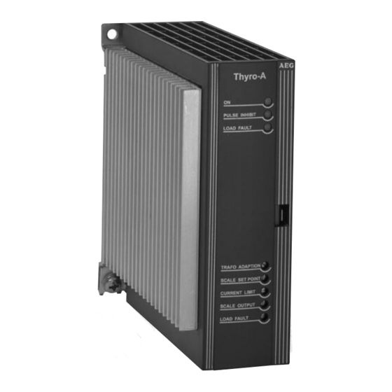
Page 34: Fig. 5 Operating Elements
PULSE INHIBIT LOAD FAULT Analog output 10V / 20 mA Chap. 3.1.5 Live zero analog output Set point value input Chap. 3.1.4 Set point value input Live zero set point Chap. 3.1.3 Control type Chap. 3.1.2 Control type Control type Operation mode Chap. -
Page 35: Fig. 6 Thyro-A...h Rl1, ...H Rlp
X3 Indicator relay Fig 6 Thyro-A...HRL 1, ...H RLP With its system interface terminal strip X22 the Power Controller Thyro-A can be connected via an optional bus module to, for example, Profibus DP or Modbus RTU (other bus modules available on request). Description and connections can be taken from the instructions of the respective components. -
Page 36: Synchronization Syt-9 (Operating Mode Takt)
The following controllers receive their impulses at X2.7 from sync. output X2.6 of the previous controller. With the last controller X2.6 remains free (series connection). This synchronization method is only possible with Thyro-A (refer to Fig. 9). 6.3 Software synchronization (operating mode TAKT) -
Page 37: Fig. 7 Connecting Diagram 1A
➜ 7. Connecting diagrams Fig. 7 Connecting diagram 1A... -
Page 38: Fig. 8 Connecting Diagram 2A
Fig. 8 Connecting diagram 2A... -
Page 39: Fig. 10 Connecting Diagram For Qtm
System - Interface Fig. 9 Connecting diagram for auxiliary supply and connection to bus module Mains load optimization with QTM Fig. 10 Connecting diagram for QTM Mains load optimization with SYT9 Abb. 11 Connecting diagram for SYT9... -
Page 40: Installation
8. Special remarks 8.1 Installation Thyro-A requires a vertical fitting position. With cabinet mounting sufficient ventila- tion of the cabinet must be ensured. The distance between the Power Controller and the cabinet ceiling or other mountings should be at least 150mm. The distance be- low the Power Controller should be at least 100mm. -
Page 41: Service
The default settings of the potentiometer can be taken from the following table. Setting Chapter Phase angle 1. half wave Default act. Setting Thyro-A 1A: 60°el R201 3.2.1 Thyro-A 2A: 90°el Set point value input control end U-Control: U +10% R202 3.2.2... -
Page 42: Checklist
- Check control characteristic adjustment (U, I, live-zero) - Check control end for correct setting ➜ 9. Type overview The type key comprises from left to right: Type range Thyro-A Number of controlled phases 1A, 2A Mains supply voltage 230, 400, 500 (V) Type current 30 ... -
Page 43: Thyro-A 1A...h Rl 1, ...H Rlp
9.1 Thyro-A 1A...H RL1, ...H RLP Thyristor controller with integrated semiconductor fuse, system bus interface, additio- nal 24VDC/AC control voltage supply, relay indication, load current monitoring and analog output, channel separation, synchronization option (for TAKT: with SYT9 for QTM integrated), with operating modes TAKT, VAR, Quick-Takt Mode and the con-... -
Page 44: Technical Data
QTM = fast half wave pulse (only for types 1A) Set point inputs The Power Controller Thyro-A has 2 set point inputs. The set point inputs are indirectly connected to the mains (SELV, PELV). Set point 1: External set point input signal ranges: 0(4) - 20mA R = ca. - Page 45 Control characteristic The control characteristic is established by the maximum value of the dimensions to be controlled and the key values of the set point. Using these key values, the linear control characteristic may be set as desired. Each controller (e.g. temperature controller) whose output signal lies within the range 0-20mA / 0-5V / 0-10V, can easily be adapted to the Power Controller.
- Page 46 11,5 22.5 M 10 Ventilation data 230V, 50-60Hz Thyro-A Type current 50Hz Type current 60Hz Air volume 1A 280 F 0.13A 0.13A 120m 2A 280 F 0.25A 0.26A 200m The ventilators must run with Thyro-A switched on, connection to X7...
- Page 47 ➜ 11. Dimensional drawings Thyro-A 1A (8 H) Dimensional drawing 910 Thyro-A 1A (16 H, 30 H) Dimensional drawing 911...
- Page 48 Thyro-A 1A (45 H, 60H) Dimensional drawing 943 Thyro-A 1A (100 H) Dimensional drawing 944...
- Page 49 Thyro-A 1A (130 H, 170 H) Dimensional drawing 946 Thyro-A 1A (280 HF) Dimensional drawing 948...
- Page 50 M 4 for protective earthing Thyro-A 1A (130 H, 170 H) Dimensional drawing 000 M 4 for protective earthing Thyro-A 1A (280 HF) Dimensional drawing 001...
- Page 51 M 6 for protective earthing Thyro-A 2A (45 H, 60H) Dimensional drawing 003 M 6 for protective earthing Thyro-A 2A (100 H) Dimensional drawing 004...
- Page 52 M 10 for protective earthing Thyro-A 2A (130 H, 170 H) Dimensional drawing 006 M 6 for protective earthing Thyro-A 2A (280 HF) Dimensional drawing 008...
-
Page 53: Accessories And Options
Order no. 2000 000 849 Bus module connector cable for 4 conntrollers, 1.5m long ➜ 13. Approvals and conformities The following approvals and conformities are available for Thyro-A • Quality standard according to DIN EN ISO 9001 • UL registration, file no. E 135074, under preparation, with consideration to Canadian National Standard, project no. - Page 54 In detail Conditions for use Built-in unit (VDE 0160) DIN EN 50 178 General requirements DIN EN 60146-1-1:12.97 Design, vertical installation Operating conditions DIN EN 60 146-1-1; K. 2.5 Operating location, industry sector CISPR 6 Temperature behaviour DIN EN 60 146-1-1; K 2.2 Storage temperature -25°C - +55°C Transport temperature E...
- Page 55 Weltweit ist AEG SVS auf allen wichtigen Märkten durch Vertriebspartner vertreten. AEG SVS is represented by sales partners in all important markets world wide. Die aktuellen regionalen Adressen finden Sie im Internet: http://www.aegsvs.de You can find the current adresses on the Internet: http://www.aegsvs.de...