Hitachi H 45MR Technical Data And Service Manual
Hitachi h 45mr electric hammer - technical data and service manual
Hide thumbs
Also See for H 45MR:
- Safety instructions and instruction manual (52 pages) ,
- Handling instructions manual (46 pages) ,
- Handling instructions manual (30 pages)

Related Manuals for Hitachi H 45MR


Summary of Contents for Hitachi H 45MR
- Page 1 MODEL H 45MR POWER TOOLS TECHNICAL DATA HAMMER H 45MR SERVICE MANUAL LIST No. E463 MAY 2002 SPECIFICATIONS AND PARTS ARE SUBJECT TO CHANGE FOR IMPROVEMENT...
- Page 2 REMARK: Throughout this TECHNICAL DATA AND SERVICE MANUAL, a symbol(s) is(are) used in the place of company name(s) and model name(s) of our competitor(s). The symbol(s) utilized here is(are) as follows: Competitors Symbols Utilized Model Name Company Name HM1100C MAKITA GSH5E BOSCH...
-
Page 3: Table Of Contents
8-7. Adjusting Mechanism for the Tool Swivel Angle ................12 8-8. Side Handle ..........................12 9. REPAIR GUIDE ..........................13 9-1. Precautions and Suggestions for Disassembly and Reassembly of the Main Body ....13 10. STANDARD REPAIR TIME (UNIT) SCHEDULES ..............18 Assembly Diagram for H 45MR... -
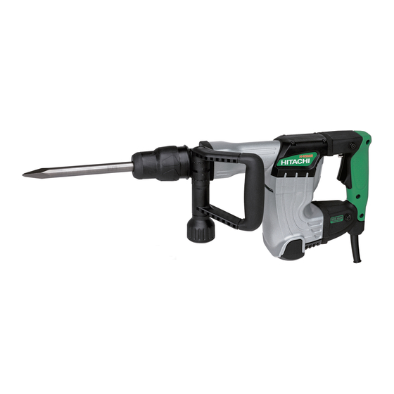
Page 4: Product Name
Hitachi Electric Hammer, Model H 45MR 2. MARKETING OBJECTIVE The Model H 45MR is an upgraded version of the current Model H 45MA, which features the use of maker B's SDS-max shank tools. The performance, durability and operability are greatly improved. With this competitive Model H 45MR, we aim to enhance the share of the SDS-max type hammers. -
Page 5: Selling Point Descriptions
Conventional mechanism for prevention of idle hammering is to open and close the air holes according to the movement of the striker. The Model H 45MR has air holes located at the position unaffected by the rebound of the striker at no load. The air holes are opened and closed by the movement of sleeve (A) provided around the cylinder that interlocks with the tool and the second hammer to prevent idle hammering. -
Page 6: Specifications
4-1-8. Original design vibration-absorbing handle (Vibration-absorbing is significantly improved) Hitachi's original design vibration-absorbing handle minimizes vibration through the rolling and compression of four cylindrical rubber cushions on inclined surfaces. The spring constant factor is as low as that of the Models H 45SB2, H 41SC, H 45SR, H 60KA, H 60MA and H 60MB, and the cushioning structure greatly reduces vibration. -
Page 7: Optional Accessories
5-1. Optional Accessories (1) Demolition work (1) Bull point (SDS max shank type) Overall length Code No. 280 mm (11-1/32") 313471 400 mm (15-3/4") 313472 (2) Grooving and chiseling work (1) Cold chisel (SDS max shank type) Overall length Code No. 280 mm (11-1/32") 313473 400 mm (15-3/4") - Page 8 (5) Roughing surface work (1) Bushing tool (2) Shank (SDS max shank type) Code No. Overall length Code No. 220 mm (8-21/32") 313477 313479 (6) Tamping work (1) Rammer (2) Shank (SDS max shank type) Code No. Overall length Code No. 220 mm (8-21/32") 313478 313479...
-
Page 9: Comparisons With Similar Products
6. COMPARISONS WITH SIMILAR PRODUCTS 6-1. Specification Comparison Maker HITACHI Model name H 45MR H 45MA For Europe, Australia, Asia U.S.A. etc. 1,050 1,050 1,100 Power input 12.5 Striking energy per stroke 4.7 --- 9.6 2.0 --- 12.0 3,000 3,000... -
Page 10: Full-Load Vibration Level Comparison
6-3. Full-load Vibration Level Comparison The graph shown in Fig. 2 illustrates the relationship between handle pressing force and handle vibration level in the Z direction. 126.0 HITACHI H 45MR HITACHI H 45MA 124.0 Normal pressing force range 122.0 120.0 118.0... -
Page 11: Precautions In Sales Promotion
7. PRECAUTIONS IN SALES PROMOTION In the interest of promoting the safest and most efficient use of the Model H 45MR Electric Hammer by all of our customers, it is very important that at the time of sale the salesperson carefully ensures that the buyer seriously recognizes the importance of the contents of the Handling Instructions, and fully understands the meaning of the precautions listed on the Caution Plate attached to each tool. -
Page 12: O-Ring Replacement
7-4. O-Ring Replacement The O-rings (mounted on the striker and piston) are extremely important to ensure adequate sealing of the air pressure. Although the O-rings are made of special rubber to give them a long service life, they do nonetheless become worn, and should be replaced by new ones periodically depending on frequency of use of the tool. -
Page 13: Idling-Proof Mechanism
(A) then the cushion (damper (A)) provided between hammer holder (A) and the front cover absorbs the striking force of the second hammer. Thus the durability of the Model H 45MR is increased greatly because the second hammer does not strike the tool retainer directly. -
Page 14: Sealed And Dustproof Construction
8-5. Vibration Absorbing Construction Hitachi original, innovative units which absorb vibration are installed between the switch handle and the cylinder crank case and between the switch handle and the housing. As a result, the amount of vibration transmitted from the main body to the arms of the operator is considerably less in comparison with conventional hammers. -
Page 15: Tool Retainer
8-6. Tool Retainer The Model H 45MR is equipped with a slide-type tool retainer. Tools can be attached and detached just by pulling grip (A). While pulling grip (A) in direction, insert the tool in the hole of the front cap (Fig. 9). Adjust the groove position by turning the tool and push it in to the end. -
Page 16: Repair Guide
9. REPAIR GUIDE 9-1. Precautions and Suggestions for Disassembly and Reassembly of the Main Body The numbers in [Bold] correspond to the item numbers in the Parts List and exploded assembly diagrams. 9-1-1. Disassembly Retainer disassembly (See Figs. 12 and 13.) Pull Grip (A) [2] fully in the arrow direction as shown in Fig. - Page 17 First gear and crank shaft disassembly Remove the grease from the Connecting Rod [34] side and the First Gear [53] side of the Cylinder Crank Case [48]. Remove the two Seal Lock Hex. Socket Flat Hd. Bolts M5 x 12 [44] fixing Bearing Cover (A) [45]. Then place the Connecting Rod [34] side of the Cylinder Crank Case [48] downward on a workbench and apply pressure on the end surface of the Crank Shaft [42] with a hand press to remove the First Gear [53] and the Crank Shaft [42] (Fig.
- Page 18 Apply Hitachi Motor Grease No. 29 to the Needle Bearing (M661) [54], the pinion portion of the Armature [70], the Needle Roller D8 x 20 [5] and the Steel Ball D6.35 [11]. Seal 20 g of the Hitachi Motor Grease No. 29 into the Cylinder Crank Case [48] (the First Gear [53] side).
- Page 19 Oil seals Be very careful not to damage the O-ring (1AS-50) [15] on the Front Cover [13], the O-ring (S-34) [14] in the Front Cover [13], the O-ring (S-25) [19] in Hammer Holder (A) [18], the O-ring (1AS-60) [40] in the Crank Cover [38], the O-rings [27] in the Striker [26] and in the Piston [33], and the Oil Seal [47] in the Cylinder Crank Case [48].
- Page 20 9-1-5. Internal wiring Wiring diagram for products with noise suppressor Switch Stator Connector Brown Plug Connector Noise Armature suppressor Blue Pillar terminal Stator Fig. 18 Wiring diagram for products without noise suppressor Switch Stator Black Plug Armature White Connector Stator Fig.
-
Page 21: Standard Repair Time (Unit) Schedules
10. STANDARD REPAIR TIME (UNIT) SCHEDULES Variable 60 min. MODEL Fixed Work Flow H 45MR Housing Ass'y Stator Ass'y Gear Cover Ass'y Switch (B) Needle Bearing Cord Tail Cover Armature Ass'y Ball Bearing (6201DD) Crank Cover Ball Bearing O-ring (608VV) - Page 22 LIST NO. E463 ELECTRIC TOOL PARTS LIST HAMMER 2002 • • Model H 45MR (E1) 103 104...
- Page 23 PARTS H 45MR ITEM CODE NO. DESCRIPTION REMARKS USED 315-529 FRONT CAP 320-802 GRIP (A) 320-803 RING 320-804 NEEDLE HOLDER 313-421 NEEDLE ROLLER D8X20 320-806 SPRING (A) 317-088 RETAINING RING D42 320-810 BALL HOLDER 320-807 GRIP (B) 320-808 GRIP (C) 959-150 STEEL BALL D6.35 (10 PCS.)
- Page 24 PARTS H 45MR ITEM CODE NO. DESCRIPTION REMARKS USED 310-123 TRANSATORY UNIT 320-830 FIRST GEAR 939-299 NEEDLE BEARING (M661) 320-841 GEAR COVER ASS’Y INCLUD.54 317-107 BOLT M8 317-106 HANDLE HOLDER (B) 317-105 HANDLE HOLDER (A) 320-635 BAND 317-108 GRIP 317-103 SIDE HANDLE ASS’Y...
-
Page 25: Standard Accessories
PARTS H 45MR ITEM CODE NO. DESCRIPTION REMARKS USED 307-028 TAPPING SCREW (W/FLANGE) D4X25 (BLACK) 959-140 CONNECTOR 50091 (10 PCS.) FOR AUS,GBR,EUROPE,NOR,SWE,DEN,FIN,SUI 938-307 PILLAR TERMINAL FOR AUS,GBR,EUROPE,NOR,SWE,DEN,FIN,SUI, USA,CAN 959-141 CONNECTOR 50092 (10 PCS.) EXCEPT FOR USA,CAN SDS MAX LABEL 984-750...