Table of Contents
Advertisement
Quick Links
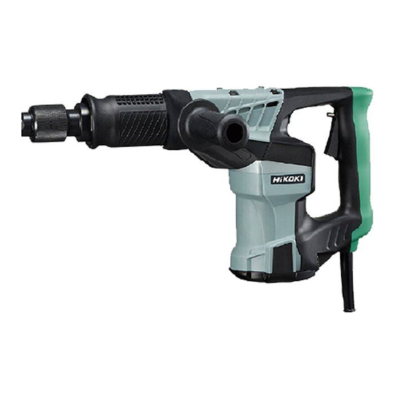
PRODUCT NAME
Hitachi Demolition Hammer
H 41SD
Model
CONTENTS
REPAIR GUIDE ---------------------------------------------------------------------------------------------------------------- 1
1. Precautions on disassembly and reassembly ----------------------------------------------------------- 1
STANDARD REPAIR TIME (UNIT) SCHEDULES -------------------------------------------------------------------- 8
International Sales Division
-6-
LIST No.
H 41SD: F413
Nov. 2012
Page
H
Advertisement
Table of Contents

Related Manuals for Hitachi H 41SD


Summary of Contents for Hitachi H 41SD
- Page 1 LIST No. H 41SD: F413 Nov. 2012 PRODUCT NAME Hitachi Demolition Hammer H 41SD Model CONTENTS Page REPAIR GUIDE ---------------------------------------------------------------------------------------------------------------- 1 1. Precautions on disassembly and reassembly ----------------------------------------------------------- 1 STANDARD REPAIR TIME (UNIT) SCHEDULES -------------------------------------------------------------------- 8 International Sales Division...
-
Page 2: Repair Guide
1. Precautions on disassembly and reassembly [Bold] numbers in the descriptions below correspond to item numbers in the Parts List and exploded assembly diagram for the Model H 41SD. Disassembly 1. Disassembly of the hammering mechanism (a) Second Hammer [12], Piston [23] and Striker [20] Note that the front cover and the cylinder case cannot be loosened. - Page 3 Fig. 1 Cylinder Case Ass’y [5] Damper [14] Second Hammer [12] Cylinder [19] Front cover ass’y Hammer Holder [2] Striker [20] Damper Washer [13] Retainer Damper [1] Cylinder case Retaining Ring for D10 Shaft [26] Piston [23] Connecting Rod [24] Crank Shaft [31] (b) First Gear [45] and Crank Shaft [31] Remove the Seal Lock Hex.
- Page 4 Fig. 2 Retaining Ring for D40 Hole [32] Crank Shaft [31] First Gear [45] Crank Case [44] Crank Case [44] Support Crank Shaft [31] 2. Disassembly of the tool retainer Use a snap ring remover to remove the retaining ring. The ring, slide grip, spring and six steel balls can then be removed from the Cylinder Case Ass’y [5] as shown in Fig.
- Page 5 Reassembly Conduct reassembly by reversing the order of the disassembly procedure. However, special attention should be given to the following items. 1. Reassembly of the hammering mechanism (a) First Gear [45] and Crank Shaft [31] Press-fit the Oil Seal [35] into the Crank Case [44] and mount the O-ring (S-40) [34]. Then press-fit the Ball Bearing 6203DDCMPS2L [33].
- Page 6 Fig. 5 Damper Washer [13] Damper [14] Second Hammer [12] Cylinder [19] (c) Valve [37], Valve Cover [38], and Felt [39] Stick the Felt [39] on the Valve Cover [38] mating their top edges after degreasing the location on the Valve Cover [38] where the felt is to be adhered. Fix the Felt [39] to the Valve Cover [38] with the O-ring (S-10) [87].
-
Page 7: Tightening Torque
O-ring (A) [15] of the Piston [23], and lip portions along the inner circumference of the Oil Seal [35] and Damper [14] • Filling Hitachi Motor Grease No. 29 First Gear [45] side and Gear Cover Ass’y [48] side in the Crank Case [44]: 10 g in total •... -
Page 8: Internal Wiring
Internal wiring (1) Wiring diagram for products without a noise suppressor Switch Stator ass’y Armature ass’y Plug Connector or pillar terminal (2) Wiring diagram for products with a noise suppressor Switch Stator ass’y Connector Armature ass’y Noise suppressor Plug Connector Pillar terminal Insulation tests Upon the completion of disassembly and repair, measure the insulation resistance and dielectric strength. -
Page 9: Standard Repair Time (Unit) Schedules
STANDARD REPAIR TIME (UNIT) SCHEDULES Variable MODEL 60 min Fixed Work Flow H 41SD Handle Cover Housing Ass’y Switch (B) Stator Ass’y Cord Gear Cover Cord Armor Ass’y Needle Bearing Armature Ball Bearing Tail Cover (6201DD) Ball Bearing (608VV) Crank Cover... - Page 10 LIST NO. F413 HAMMER 2012 · 11 · 16 Model H 41SD (E2)
- Page 11 PARTS H 41SD ITEM CODE NO. DESCRIPTION REMARKS USED 334-946 RETAINER DAMPER 334-950 HAMMER HOLDER 333-856 RETAINING RING D45 333-855 FRONT WASHER 334-945 CYLINDER CASE ASS'Y INCLUD. 11 333-854 CYLINDER CASE COVER 333-261 BAND 991-712 HEX. SOCKET HD. BOLT (W/FLANGE) M6 X 25...
- Page 12 PARTS H 41SD ITEM CODE NO. DESCRIPTION REMARKS USED 360-946C ARMATURE 110 V 360-946E ARMATURE 220 V-230 V 360-946F ARMATURE 240 V 331-252 FAN GUIDE 953-121 HEX. HD. TAPPING SCREW D5 X 50 990-861 INTERNAL WIRE FOR EUROPE, AUS, NZL, SAF, TPE, KOR 340-788B STATOR ASS'Y 110 V INCLUD.
-
Page 13: Standard Accessories
STANDARD ACCESSORIES H 41SD ITEM ITEM ITEM CODE NO. CODE NO. CODE NO. DESCRIPTION REMARKS USED USED 980-752 BULL POINT 280 MM (HEX. SHANK TYPE) 333-862 CASE OPTIONAL ACCESSORIES ITEM CODE NO. DESCRIPTION REMARKS USED 980-753 BULL POINT 450 MM (HEX. SHANK TYPE) 234-001 BULL POINT 280 MM (10 PCS.)