
Related Manuals for Honeywell HVE1


Summary of Contents for Honeywell HVE1
- Page 1 HVE1/HVE4/HVE8 Audio/Video Encoder Audio/Video Encoder HVE1 HVE1X HVE4 HVE4X HVE8 HVE8X Getting Started Guide Document 800-15611V2 – Rev A – 10/2013...
- Page 2 Revisions Issue Date Revisions 08/2013 New document V1 Rev A 10/2013 Removed Preliminary status. Adjusted alignment and layout. Minor text changes throughout. V2 Rev A 10/2013 Replaced the photo of the HVE8(X) back panel. Corrected the callouts in Fig 3. Removed references to the microSD card and PoE for HVE8(X).
-
Page 3: Cautions And Warnings
Cautions and Warnings THIS SYMBOL INDICATES THAT CAUTION DANGEROUS VOLTAGE RISK OF ELECTRIC CONSTITUTING A RISK OF SHOCK ELECTRIC SHOCK IS PRESENT DO NOT OPEN WITHIN THE UNIT. CAUTION: TO REDUCE THE RISK OF ELECTRIC THIS SYMBOL INDICATES THAT SHOCK, DO NOT REMOVE THE COVER. IMPORTANT OPERATING AND•... -
Page 4: Manufacturer's Declaration Of Conformance
10 | HVE1/HVE4/HVE8 Encoders Getting Started Guide Manufacturer’s Declaration of Conformance North America The equipment supplied with this guide conforms to UL 60950-1 and CSA C22.2 No. 60950-1. Europe The manufacturer declares that the equipment supplied is compliant with the essential requirements of the EMC directive 2004/108/EC, conforming to the requirements of standards EN 55022 for emissions, EN 50130-4 for immunity, and EN 60950 for electrical equipment safety. -
Page 5: Installing The Hard Disk Drive (Hdd)
Unauthorized substitutions may result in fire, electric shock or other hazards. Installation The HVE1(X)/HVE4(X)/HVE8(X) encoders are highly advanced surveillance equipment that should be installed with care. Please ensure that you install a manufacturer-recommended HDD (HVE8(X) models only). See Table 1-1 for a list of recommended HDDs. -
Page 6: Installing The Hdd
12 | HVE1/HVE4/HVE8 Encoders Getting Started Guide Before installing a HDD for HVE(X), please ensure the power is disconnected from the device. Only a factory-recommended HDD should be used for this installation. Table 1 Tested Compatible HDDs SEAGATE Capacity HDD Model... - Page 7 | 13 Figure 1 Removing the Cover Place the HDD into the slot on the chassis, and then secure it in position by tightening the screws at the bottom of the chassis. Figure 2 Installing and Securing the HDD Install Secure Remove the HDD data line from the accessories box.
-
Page 8: About The Encoder
14 | HVE1/HVE4/HVE8 Encoders Getting Started Guide About the Encoder HVE1(X) Front Panel Figure 4 HVE1 Front Panel Table 2 HVE1 Front Panel Interface Element Function PWR LED Indicator Lights red when the device is powered on. Lights orange when an SD card is inserted. -
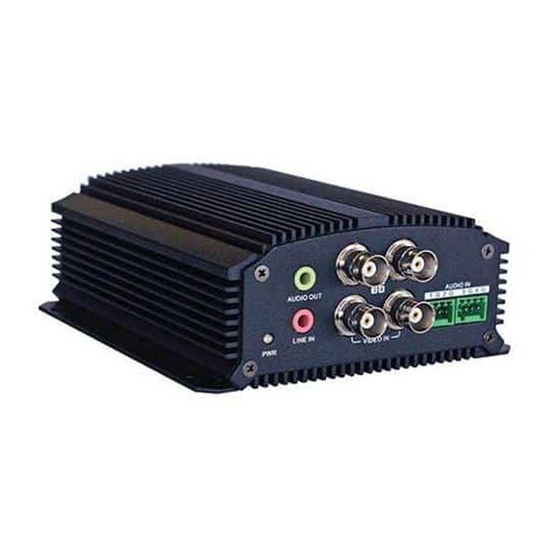
Page 9: Rear Panel
The right LED indicator lights green when the network cable is connected. The left LED indicator blinks orange when data is transmitting/receiving. DC 12V 12 V DC power supply Ground Note The HVE1 model encoder does not support/supply a beeper/audio alert. 800-15611V2 - A - 10/2013... - Page 10 16 | HVE1/HVE4/HVE8 Encoders Getting Started Guide HVE4(X) Front Panel Figure 6 HVE4 Front Panel Table 4 HVE1 Front Panel Interface Element Function PWR LED Indicator Lights red when the device is powered on. Lights orange when the SD card is inserted.
- Page 11 | 17 Rear Panel Figure 7 HVE4 Rear Panel Table 5 HVE1 Rear Panel Interface Element Function ALARM IN Relay alarm input. ALARM OUT Relay alarm output. The maximum voltage/current supported by the relay output is 12 V / 1 A.
- Page 12 18 | HVE1/HVE4/HVE8 Encoders Getting Started Guide HVE8(X) Front Panel Figure 8 NVE8 Front Panel Table 6 HVE1 Front Panel Interface Element Function POWER Lights red when the device is powered on. STATUS Lights red when data is being read from or written to the HDD.
-
Page 13: Installing The Ip Utility
To discover the IP device and configure the network settings, you must first install the IP Utility. For more information, see the user guide on the software CD that came with your encoder, or go to the Honeywell web site. You must have Windows administrator privileges for the workstation onto which the Honeywell IP Utility is being installed. -
Page 14: Configuring Network Parameters
20 | HVE1/HVE4/HVE8 Encoders Getting Started Guide Figure 10 IP Utility Configuring Network Parameters If you do not know the IP address of the encoder, and this is not the first time you are using the encoder, then you can use IP Utility or the Serial port tools to find the encoder’s IP address, and to configure the IP address or other network... - Page 15 | 21 Searching for Online Devices Automatically Searching for Online Devices After you log on to the IP Utility, the devices on the network are automatically discovered and listed in the Discovery pane. After the initial discovery, auto-refresh continues to discover newly added network devices. Figure 11 Found Devices Note...
-
Page 16: Modifying Network Parameters
22 | HVE1/HVE4/HVE8 Encoders Getting Started Guide Note You can click Up or Down buttons on each column heading to reorder the information. Click >> to expand the device table, and to hide the network parameter panel on the right side. Click << to show the network parameter panel. - Page 17 Connect to your IP device by double-clicking it in the Discover pane, or by selecting it and clicking The name for the connected device turns bold and blue, and the Launch Browser button becomes active. Click Launch Browser. The Honeywell IP Utility login window opens. Figure 13...
-
Page 18: Starting Live View
24 | HVE1/HVE4/HVE8 Encoders Getting Started Guide Table 8 Supported Web Browsers Google Chrome 8 and above Apple Safari 5.0.2 and above Windows XP SP1 and above (32-bit) Open the web browser. Enter the encoder’s IP address (default: 192.168.0.250), and then press Enter on your keyboard. - Page 19 | 25 Figure 15 Live View Window Click to start Live View for all of the cameras in the device list. Table 9 Controls on the Live View Window Icon Function Select the viewing window division. Start/stop live view. Capture pictures in the live view mode. Manually start/stop recording.
-
Page 20: Operating Ptz Control
26 | HVE1/HVE4/HVE8 Encoders Getting Started Guide Operating PTZ Control Before you begin: • Ensure the encoder is connected to a camera/dome which supports pan/tilt/zoom control. Connect the R+ and R- terminals on the PTZ unit or speed dome to the RS-485 T+ and RS-485 T- terminals on the encoder. - Page 21 | 27 Scheduled Recording Click Configuration Remote Configuration Camera Settings Schedule Settings to enter the Recording Schedule settings interface. Select a camera for configuration. Check to enable Enable Record Schedule. Figure 17 Schedule Settings Window Click to Enable Record Schedule Click Edit to enter the Edit Schedule window.
- Page 22 28 | HVE1/HVE4/HVE8 Encoders Getting Started Guide Note Time periods cannot overlap. You can configure up to 8 time periods. Select a Recording Type from the drop-down menu. Select from Normal, Motion, Alarm, Alarm & Motion, and Motion Alarm. •...
- Page 23 | 29 Figure 20 Calendar Click Play to play the recorded video. Figure 21 Recorded Video Playing in the Playback Window Use the buttons on the playback toolbars to control playback Figure 22 Playback Toolbars Table 11 Playback Controls Button Function Button Function...
- Page 24 30 | HVE1/HVE4/HVE8 Encoders Getting Started Guide Figure 23 Progress Bar • Enter the time in the time selector and click to locate the playback point. Figure 24 Time Selector The color of the video on the progress bar indicates the type of video.
- Page 25 | 31 Note Up to 100 log files can be displayed at a time. Saving Log Files Click to save the found log files to a local directory. 800-15611V2 - A - 10/2013...
- Page 26 Document 800-15611V2 – Rev A – 10/2013 © 2013 Honeywell International Inc. All rights reserved. No part of this publication may be reproduced by any means without written permission from Honeywell. The information in this publication is believed to be accurate in all respects. However, Honeywell cannot assume responsibility for any consequences resulting from the use thereof.