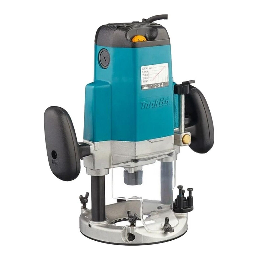
Makita 3612C Instruction Manual
Electronic router
Hide thumbs
Also See for 3612C:
- Instruction manual (29 pages) ,
- Parts breakdown (3 pages) ,
- Instruction manual (72 pages)
Summary of Contents for Makita 3612C
- Page 1 Router Electronic Router MODEL 3612 MODEL 3612C 005064 003647 DOUBLE INSULATION I N S T R U C T I O N M A N U A L WARNING: For your personal safety, READ and UNDERSTAND before using. SAVE THESE INSTRUCTIONS FOR FUTURE REFERENCE.
-
Page 2: Specifications
These values have been obtained according to must be collected separately and EN50144. returned to an environmentally com- For Model 3612C patible recycling facility. For European countries only Intended use Noise and Vibration The tool is intended for flush trimming and profiling of The typical A-weighted sound pressure level is 83 dB (A). -
Page 3: Safety Instructions
Responsible manufacturer: ardized documents, HD400, EN50144, EN55014, Makita Corporation Anjo Aichi Japan EN61000 in accordance with Council Directives, 73/23/ EEC, 89/336/EEC, 98/37/EC. Yasuhiko Kanzaki CE 2004 Director SAFETY INSTRUCTIONS ENA001-2 WARNING:... -
Page 4: Additional Safety Rules
17. Avoid unintentional starting. damaged should be properly repaired or replaced Do not carry a plugged-in tool with a finger on the by an authorized service center unless otherwise switch. Ensure switch is off when plugging in. indicated in this instruction manual. Have defective 18. -
Page 5: Functional Description
FUNCTIONAL CAUTION: DESCRIPTION • Always be sure that the tool is switched off and unplugged before adjusting or checking function on the tool. Adjusting the depth of cut 003652 Place the tool on a flat surface. Loosen the lock lever and lower the tool body until the bit just touches the flat surface. - Page 6 1. Lock-off button 2. Switch trigger Speed adjusting dial For model 3612C only 003802 The tool speed can be changed by turning the speed adjusting dial to a given number setting from 1 to 5.
-
Page 7: Operation
C00118 Number 9,000 12,000 15,000 19,000 23,000 CAUTION: • If the tool is operated continuously at low speeds for a long time, the motor will get overloaded, resulting in tool malfunction. • The speed adjusting dial can be turned only as far as 5 and back to 1. Do not force it past 5 or 1, or the speed adjusting function may no longer work. - Page 8 001984 1. Workpiece 2. Bit revolving direction 3. View from the top of the tool 4. Feed direction 001985 NOTE: • Moving the tool forward too fast may cause a poor quality of cut, or damage to the bit or motor. Moving the tool forward too slowly may burn and mar the cut.
- Page 9 Wider straight guide of desired dimensions may be made by using the conven- 003684 ient holes in the guide to bolt on extra pieces of wood. When using a large diameter bit, attach pieces of wood to the straight guide which have a thickness of more than 15 mm to prevent the bit from striking the straight guide.
- Page 10 Secure the templet to the workpiece. Place the tool on the templet and move 003695 the tool with the templet guide sliding along the side of the templet. NOTE: • The workpiece will be cut a slightly different size from the templet. Allow for the distance (X) between the bit and the outside of the templet guide.
- Page 11 3. Workpiece Dust cover (Accessory) 005079 To suit the tool when using in the inverted position with Makita Router Stand. This accessory prevents sawdust from being drawn through the tool in the inverted position. It is not recommended for use in the normal position. However, we do recom- mend its use in the inverted mode.
- Page 12 Use the vacuum head for dust extraction. Install the vacuum head on the tool 005074 base using the two screws. 1. Vacuum head 2. Screws For tool with lock plate 005075 Use the vacuum head for dust extraction. To Install the vacuum head, raise the lock lever on it.
-
Page 13: Maintenance
CAUTION: • These accessories or attachments are recommended for use with your Makita tool specified in this manual. The use of any other accessories or attachments might present a risk of injury to persons. Only use accessory or attachment for its stated purpose. - Page 14 Router bits Straight bit 005116 C00121 1/4” 1/2” 1/2” 1/4” 1/4” 1/2” “U”Grooving bit 005117 C00122 1/2” 1/4” “V”Grooving bit 005118 C00123 θ 90° 1/4” Dovetail bit 005119 C00124 θ 14.5 35° 15SE 3/8” 14.5 14.5 23° 15LE 3/8” 30° 3/8”...
- Page 15 Drill point flush trimming bit 005120 C00125 1/2” 3/8” 1/4” Drill point double flush trimming bit 005121 C00126 1/2” 3/8” 1/4” Slotting cutter 005122 C00127 1/2” 1/2” Board-jointing bit 005123 C00128 1/2” 1/2” 005124...
- Page 16 Corner rounding bit 005125 C00129 1/4” 1/2” 1/4” Chamfering bit 005127 C00130 1/2” C00131 005126 θ 30° 30° 30° E 1/4” 45° 45° 45° E 1/4” 60° 60° 60° E 1/4” Beading bit 005128 C00132 1/2” Cove beading bit 005129 C00133 1/4”...
- Page 17 Ball bearing flush trimming bit 005130 C00134 1/4” Ball bearing corner rounding bit 005131 C00135 1/4” 1/4” Ball bearing chamfering bit 005132 C00136 θ 45° 45° 45° E 1/4” 60° 60° 60° E 1/4” Ball bearing beading bit 005133 C00137 1/4”...
- Page 18 Ball bearing roman ogee bit 005135 C00139 1/4” 1/4” Double ball bearing round corner bit 005136 C00140 1/2”...
- Page 19 Memo...
- Page 20 Makita Corporation Anjo, Aichi, Japan 883865D229...


