Table of Contents
Advertisement
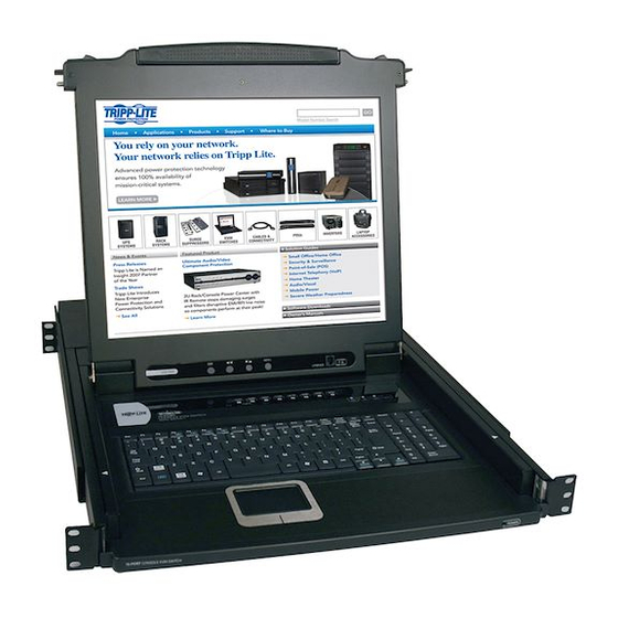
Owner's Manual
8- or 16-Port 1U Console KVM Switch or
16-Port 1U Rackmount KVM Switch
Model #: B020-008, B020-008-17, B020-016, B020-016-17 or B022-016
This package should consist of:
• 1 KVM Switch (B020-008, B020-008-17, B020-016, B020-016-17 or B022-016)
• 1 USB Keyboard/Mouse Adapter
• 1 Power Adapter with Power Cord
• Firmware Upgrade Cable
• 1 Owner's Manual with Quick Start Guide
• 1 Rackmount Kit (B022-016 only)
Check to see that the unit arrived undamaged, with all of its contents. Contact your dealer if there is a problem.
Tripp Lite World Headquarters
1111 W. 35th Street, Chicago, IL 60609 USA
(773) 869-1234, www.tripplite.com
NOTE: Follow these instructions and operating procedures to ensure correct performance
and to prevent damage to this unit or to its connected devices.
Copyright © 2005 Tripp Lite. All rights reserved. All trademarks are the property of their respective owners.
The policy of Tripp Lite is one of continuous improvement. Specifications are subject to change without notice.
Advertisement
Table of Contents

Related Manuals for Tripp Lite B020-008


Summary of Contents for Tripp Lite B020-008
- Page 1 Copyright © 2005 Tripp Lite. All rights reserved. All trademarks are the property of their respective owners. The policy of Tripp Lite is one of continuous improvement. Specifications are subject to change without notice.
-
Page 2: Table Of Contents
Specifications ... 25 Appendix B ... 26 Clear Log-in Information ... 26 Appendix C ... 27 Removing the KVM Module from the B020-008, B020-008-17, B020-016 and B020-016-17 ...27 Removing the Keyboard and Touchpad from the B020-008, B020-008-17, B020-016 and B020-016-17 ... 27 Appendix D ... -
Page 3: Overview
(keyboard, mouse, and monitor). Features Include: • Integrated KVM Console on the B020-016 and B020-008 Console KVM—Includes a 15" LCD Monitor, Keyboard and Touchpad in a 1U Rackmount Housing • Integrated KVM Console on the B020-016-17 and B020-008-17 Console KVM—Includes a 17" LCD Monitor, Keyboard and Touchpad in a 1U Rackmount Housing •... -
Page 4: System Requirements
Note: On the B020-016 and B020-008, since the integrated LCD monitor’s maximum resolution is 1024 × 768, the computer’s resolution setting must not exceed 1024 × 768. The B020-016-17 and B020-008-17 have a maximum resolution of 1280 x 1024, so the computer's resolution setting must not exceed 1280 x 1024. -
Page 5: Introduction
• Firmware Upgrade Port: The Firmware Upgrade Cable that transfers the firmware upgrade data from the administrator’s computer to the B020-008 or B020-016 plugs into this RJ-11 connector. • Firmware Upgrade Switch: During normal operation this switch should be in the NORMAL position. -
Page 6: B022-016
ELECTED Front View of B022-016 1. Port LEDs Port LEDs provide status information about their corresponding CPU Ports. The top row of LEDs corresponds to Ports 1 - 8; the bottom row corresponds to Ports 9 - 16. There are two LEDs for each Port. The left one is the On-Line LED;... -
Page 7: Rear View
This is a standard rocker switch that powers the unit On and Off. 5. External Console Section For flexibility and convenience, the B020-016/B020-008 supports an independent, external, KVM console. The external console’s keyboard, monitor, and mouse cables plug in here. -
Page 8: Installation
To set up a sin- gle-stage installation, do the following: 1. Use the correct Tripp Lite KVM cable kits (as described in the Cables page 4), to connect a computer’s Keyboard, Video and Mouse ports to any available port on the KVM switch. -
Page 9: Lcd Osd (On-Screen Display) Configuration
LCD OSD (On-Screen Display) Configuration The LCD OSD allows you to set up and configure the LCD display: • To open up the LCD OSD main menu, press the button marked Menu. • Use the s and tbuttons to navigate and make adjustments. After navigating to a setting choice, use the Menu button to bring up the adjustment screen. -
Page 10: Basic Operation
• Press buttons 1 & 2 simultaneously for two seconds to perform a keyboard and mouse reset. • Press buttons 7 & 8 (B020-008/B020-008-17) or 15 & 16 (B020-016/B020-016-17) simultaneously for two seconds to invoke Auto Scan Mode (see p. 12). -
Page 11: Hot Plugging
Basic Operation Hot Plugging All KVM Switches support hot plugging—components can be removed and added back into the installa- tion by unplugging their cables from the ports without having to shut the switch down. However, in order for Hot Plugging to work properly, these procedures must be followed: Switching Station Positions Switch station positions by simply unplugging from the old parent and plugging into a new one. -
Page 12: Hotkeys
Hotkeys Port Control Using Hotkeys Hotkey Port Control lets you connect to a computer by making the port selection directly from the keyboard. The Hotkey Port Control options are: • Selecting the Active Port • Auto Scanning • Previous/Next Switching Invoking the Hotkey Mode 1) All Hotkey operations begin by invoking the Hotkey Mode. -
Page 13: Setting The Scan Interval
Setting the Scan Interval The amount of time the KVM remains on each port during Auto Scan is set using the Scan Duration setting of the OSD’s F3 SET function (see page 17). The scan interval can be changed prior to activating Hotkey Auto Scanning by performing the following: 1) Invoke Hotkey Mode with the [NumLock] + [-] combination 2) Key in [T] [n]... -
Page 14: Skip Mode
Skip Mode This feature allows you to manually sequence between computers in order to monitor them. This manual version of the Auto Scan mode lets you dwell on a particular port for as long as you like. To invoke Previous/Next Switching, key in the following Hotkey combination: 1) Invoke Hotkey Mode with the [NumLock] + [-] combination 2) Key in [Arrow] refers to the arrow keys on the keyboard. -
Page 15: Osd (On-Screen Display) Operation
OSD (On-Screen Display) Operation OSD Overview The On Screen Display (OSD) is used for all computer control and switching procedures. All procedures start from the OSD Main Menu. To pop up the Main Menu, tap the [Scroll Lock] key twice. Note: You can change the Hotkey from the [Scroll Lock] key to the [Ctrl] key (see OSD Hotkey, page 17. -
Page 16: Osd Main Screen Headings
OSD Main Screen Headings Heading Explanation SN-PN This column lists the Port ID numbers (Station Number - Port Number) for all the CPU ports on the installation. The simplest method to access a particular computer is move the Highlight Bar to it, then press [Enter]. An arrow in this column indicates that the corresponding port is selected for Quick View scanning (see Set Quick View Ports, page 18). -
Page 17: F3 Set Environment (Set)
F3 Set Environment (SET) This function allows each User and the Administrator to set up their own working environment. A separate profile for each is stored by the OSD and is activated according to the Username that was provided during Login. To change a setting: 1) Double Click the item;... -
Page 18: F4 Administrator (Adm)
F4 Administrator (ADM) F4 is an Administrator-only function. It allows the Administrator to configure and control the overall oper- ation of the OSD. To change a setting Double Click it or use the Up / Down Arrow Keys to move the high- light bar to the item and press [Enter]. -
Page 19: F5 Skip (Skp)
Setting Function SET ACCESSIBLE Allows the Administrator to define a User’s access to the computers in the installation on a PORTS Port-by-Port basis. For each User, select the target Port and press the [Spacebar] to cycle through the choices: F (Full access), V (View Only), or blank. Repeat until all access rights have been set, then press [Enter]. -
Page 20: F7 Scan (Scan)
F7 Scan (SCAN) Invoke the Auto Scan Mode by clicking the F7 field or pressing [F7]. This function allows you automatical- ly cycle through available computers at regular intervals so that you can monitor their activity without hav- ing to take the trouble of switching yourself. •... -
Page 21: Firmware Upgrade Utility
Firmware Upgrade Utility Before You Begin To prepare for the firmware upgrade, do the following: 1. From a computer that is not part of your KVM installation go to our Internet support site and choose the model name that relates to your device to get a list of available Firmware Upgrade Packages. 2. -
Page 22: Starting The Upgrade
Starting the Upgrade To upgrade your firmware: 1) Run the downloaded Firmware Upgrade Package file, either by double licking the file icon or by opening a command line and entering the full path to it. The Firmware Upgrade Utility Welcome screen appears. 2) Read and Agree to the License Agreement (click the I Agree radio button). -
Page 23: Upgrade Succeeded
Upgrade Succeeded After the upgrade has completed, a screen appears to inform you that the procedure was successful: Click Finish to close the Firmware Upgrade Utility. Upgrade Failed If the upgrade failed to complete successfully, a dialog box appears asking if you want to retry. Click Yes to retry. -
Page 24: Appendix A
After it has been successfully upgraded, plug it back into the chain. Appendix A Computer Connection Table The following tables indicate the relationship between the number of Tripp Lite KVMs and the number of computers that they control: CPUs 1 x A... -
Page 25: Troubleshooting
* Via daisy-chaining of B022-016. Possible Cause Unit not receiving enough power. Improper mouse and/or keyboard reset. Station 1 has lost power. B020-008/ B020-008-17 504* Push Button OSD (On Screen Display), Hotkeys 8 (Orange) 8 (Green) 8 × SPDB-15 F 1 ×... -
Page 26: Appendix B
Appendix B Clear Log-in Information If you are unable to perform an Administrator login (because the Username and Password information has become corrupted, or you have forgotten it), you can clear the login information with the following procedure: 1. Power off the switch and remove the top cover from the unit chassis. 2. -
Page 27: Removing The Kvm Module From The B020-008, B020-008-17, B020-016 And B020-016-17
Appendix C Removing the KVM Module from the Console KVM The KVM module can be removed from the unit chassis. To do so: 1) Slide the unit to the out position. 2) Remove the eight module attachment screws (four above; four below). 3) Remove the cable attachment clip and unplug the data cable. -
Page 28: Optional Rack Mounting
The policy of TRIPP LITE is one of continuous improvement. Specifications are subject to change without notice. WARRANTY REGISTRATION Visit www.tripplite.com/warranty today to register the warranty for your new Tripp Lite product. You'll be automatically entered into a drawing for a chance to win a FREE Tripp Lite product!* * No purchase necessary. -
Page 29: Year Limited Warranty
1111 W. 35th Street, Chicago, IL 60609 USA (773) 869-1234, www.tripplite.com Copyright © 2005 Tripp Lite. All rights reserved. All trademarks are the property of their respective owners. The policy of Tripp Lite is one of continuous improvement. Specifications are subject to change without notice.