Table of Contents
Advertisement
Quick Links
MODEL G0533
3HP DRY SPRAY BOOTH
OWNER'S MANUAL
Copyright © deCeMBer, 2005 By grizzly industrial, inC., reVised april, 2011 (trts)
WARNiNG: NO PORTiON Of THiS MANUAL MAY BE REPRODUcED iN ANY SHAPE
OR fORM WiTHOUT THE WRiTTEN APPROvAL Of GRizzLY iNDUSTRiAL, iNc.
(For MaChines MFg. sinCe 3/11) #Bl5685 printed in taiWan
Advertisement
Table of Contents

Related Manuals for Grizzly G0533


Summary of Contents for Grizzly G0533
- Page 1 3HP DRY SPRAY BOOTH OWNER'S MANUAL Copyright © deCeMBer, 2005 By grizzly industrial, inC., reVised april, 2011 (trts) WARNiNG: NO PORTiON Of THiS MANUAL MAY BE REPRODUcED iN ANY SHAPE OR fORM WiTHOUT THE WRiTTEN APPROvAL Of GRizzLY iNDUSTRiAL, iNc.
- Page 2 This manual provides critical safety instructions on the proper setup, operation, maintenance, and service of this machine/tool. Save this document, refer to it often, and use it to instruct other operators. Failure to read, understand and follow the instructions in this manual may result in fire or serious personal injury—including amputation, electrocution, or death.
-
Page 3: Table Of Contents
Table of contents iNTRODUcTiON ..........2 SEcTiON 4: OPERATiONS ......18 Manual accuracy ........... 2 Filter indicator ..........18 Contact info............ 2 SEcTiON 5: MAiNTENANcE ......20 data sheet ............. 3 schedule ............20 identification ........... 5 exhaust Fan and Motor ....... 20 SEcTiON 1: SAfETY ........ -
Page 4: Introduction
Your Machine For your convenience, we post all available man- uals and manual updates for free on our website at www.grizzly.com. Any updates to your model of machine will be reflected in these documents as soon as they are complete. -
Page 5: Data Sheet
Data Sheet MACHINE DATA SHEET Customer Service #: (570) 546-9663 · To Order Call: (800) 523-4777 · Fax #: (800) 438-5901 MODEL G0533 3 HP DRY SPRAY BOOTH Product Dimensions: Weight................................607 lbs. Width (side-to-side) x Depth (front-to-back) x Height................. 63 x 52 x 100 in. Footprint (Length x Width).......................... - Page 6 Filter Info No. Of First Stage Filters..........................6 First Stage Filter Length........................19-1/2 in. First Stage Filter Width........................15-1/2 in. First Stage Filter Thickness........................1-3/4 in. No. Of Second Stage Filters..........................6 Second Stage Filter Length......................... 19-1/2 in. Second Stage Filter Width........................15-1/2 in. Second Stage Filter Thickness......................
-
Page 7: Identification
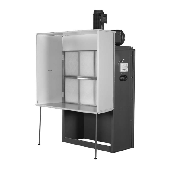
identification figure 1. g0533 identification. A. spray Booth Frame B. air Filter indicator c. First stage Filter D. right Curtain E. Work table leg Work table G. support Bar H. left Curtain top Curtain Motor Model g0533 (Mfg. since 3/11) -
Page 8: Section 1: Safety
SEcTiON 1: SAfETY For Your Own Safety, Read Instruction Manual Before Operating this Machine The purpose of safety symbols is to attract your attention to possible hazardous conditions. This manual uses a series of symbols and signal words intended to convey the level of impor- tance of the safety messages. - Page 9 DISCONNECTING POWER SUPPLY.Alwaysdis- FORCING MACHINERY.Donotforcemachine. connect machine from power supply before ser- It will do the job safer and better at the rate for vicing, adjusting, or changing cutting tools (bits, whichitwasdesigned. blades, cutters, etc.). Make sure switch is in OFF positionbeforereconnectingtoavoidanunexpect- GUARDS &...
-
Page 10: Additional Safety Instructions
Additional Safety instructions for Dry Spray Booths cODES AND STANDARDS. Follow all local fLAMMABLE MATERiAL DiSPOSAL. safely electrical, safety, and fire codes, national Fire and properly dispose used filters or paint-contam- protection association codes, the national inated items. electrical Code, and the occupational safety and health act. -
Page 11: Section 2: Power Supply
SEcTiON 2: POWER SUPPLY Availability circuit Requirements for 230v Before installing the machine, consider the avail- this machine is prewired to operate on a 230V ability and proximity of the required power supply power supply circuit that has a verified ground and circuit. -
Page 12: Section 3: Set Up
SEcTiON 3: SET UP Needed for Set Up This machine presents serious injury hazards the following items are needed to complete the to untrained users. Read set up process, but are not included with your through this entire manu- machine: al to become familiar with the controls and opera- DEScRiPTiON... -
Page 13: Inventory
inventory The following is a description of the main compo- nents shipped with your machine. Lay the compo- nents out to inventory them. If any non-proprietary parts are missing (e.g. a nut or a washer), we will gladly replace them; or for the sake of expediency, replacements can be obtained at your local hardware store. -
Page 14: Hardware Recognition Chart
Hardware Recognition chart -12- Model g0533 (Mfg. since 3/11) -
Page 15: Site Considerations
Site considerations Exhaust fan floor Load To install the exhaust fan housing: Refer to the Machine Data Sheet for the weight place the inlet gasket over the exhaust fan and footprint specifications of your machine. inlet. Some floors may require additional reinforcement to support both the machine and operator. -
Page 16: Outlet
Outlet To install the exhaust fan outlet: Place the outlet gasket and outlet over the exhaust fan, and secure with (10) ⁄ "-18 x 1" hex bolts, 20 flat washers, and 10 hex nuts, as shown in figure 5. support Bar figure 6. -
Page 17: Work Table
repeat Step 1 with the right curtain. Fasten each curtain brace to the top cover with four ⁄ "-18 x ⁄ hex bolts as shown in figure 8. Curtain Brace figure 10. top curtain attached to connector bar. Work Table figure 8. -
Page 18: Filters
Make sure the work table opens and closes smoothly. reach under the work table and fully extend the two support legs. lock the latches on the bottom of each cur- tain into the work table. filters To install the filters: figure 13. -
Page 19: Air Filter Indicator
Air filter indicator tubing Connector Fitting To install the air filter indicator: Mount the manometer to the side of the spray booth by threading the M4 x 45 tap screws into the pre-drilled holes (figure 15). figure 16. tubing installed onto spray booth chamber. -
Page 20: Section 4: Operations
Regardless of the con- zero adjustment Knob tent in this section, Grizzly industrial will not be held liable for accidents caused by figure 18. air filter indicator controls. lack of training, neglect or misuse. - Page 21 Multiply the reading from Step 6 times 2 (2x) With new filters installed, turn the spray booth ON, observe the rise in the reading, and mark and mark with the supplied red arrow (figure with the supplied green arrow as shown in the 20).
-
Page 22: Section 5: Maintenance
SEcTiON 5: MAiNTENANcE Air filter indicator Always disconnect power to the machine before Check the air filter indicator fluid level periodically performing maintenance. and refill as needed with dwyer red gauge oil. ® failure to do this may Clean the indicator with a soft, damp cloth. result in serious person- al injury. -
Page 23: Section 6: Service
SEcTiON 6: SERvicE review the troubleshooting and procedures in this section to fix or adjust your machine if a problem devel- ops. if you need replacement parts or you are unsure of your repair skills, then feel free to call our technical support at (570) 546-9663. -
Page 24: G0533 Wiring Diagram
G0533 Wiring Diagram Ground 230V Line 1 Power Supply Line 2 Have a qualified electrician install wiring according to NFPA 33, NEC, and local regulations. Thermostat wires (Not Used) Motor T3 T6 (Not Used) -22- Model g0533 (Mfg. since 3/11) -
Page 25: Main Parts Breakdown
Main Parts Breakdown 1-1V2 1-3V2 28-4 28-3 11-26 11-27 28-1 11-1 11-28 28-2 11-2 11-25 11-3 11-24 11-11 11-16 12-1 11-5 11-9 11-10 11-6 12-2 11-15 11-4 11-14 11-12 11-18 11-13 11-22 11-23 11-7 11-19 11-17 11-8 11-20 11-21 26-1 49-1 26-4 26-2... -
Page 26: Main Parts List
Main Parts List PART # DESCRIPTION PART # DESCRIPTION 1AV2 P0533001AV2 BLOWER HOUSING ASSY V2.03.11 11-20 P0533011-20 SIDE FILTER CASE SUPPORT P0533001V2 BLOWER HOUSING V2.03.11 11-21 PHTEK34 TAP SCREW 1/4 X 1/2 1-1V2 P0533001-1V2 IMPELLER 12" V2.03.11 11-22 PN05 HEX NUT 1/4-20 PB21 HEX BOLT 3/8-16 X 3/4 11-23... -
Page 27: Safety Label Placement And Parts List
Safety labels help reduce the risk of serious injury caused by machine hazards. If any label comes off or becomes unreadable, the owner of this machine MUST replace it in the original location before resuming operations. For replacements, contact (800) 523-4777 or www.grizzly.com. PART #... - Page 28 -26- Model g0533 (Mfg. since 3/11)
- Page 29 Would you recommend Grizzly Industrial to a friend? _____ Yes _____No Would you allow us to use your name as a reference for Grizzly customers in your area? Note: We never use names more than 3 times. _____ Yes _____No 10.
- Page 30 FOLD ALONG DOTTED LINE Place Stamp Here GRIZZLY INDUSTRIAL, INC. P.O. BOX 2069 BELLINGHAM, WA 98227-2069 FOLD ALONG DOTTED LINE Send a Grizzly Catalog to a friend: Name_______________________________ Street_______________________________ City______________State______Zip______ TAPE ALONG EDGES--PLEASE DO NOT STAPLE...
- Page 32 Buy Direct and Save with Grizzly – Trusted, Proven and a Great Value! ® ~Since 1983~ Visit Our Website Today For Current Specials! ORDER 24 HOURS A DAY! 1-800-523-4777...