Panasonic BT-LH1710 - Professional - LCD Production Monitor Operating Instructions Manual
Lcd video monitor
Hide thumbs
Also See for BT-LH1710 - Professional - LCD Production Monitor:
- Specifications (12 pages) ,
- Brochure & specs (12 pages) ,
- Brochure (16 pages)
Table of Contents
Advertisement
Advertisement
Table of Contents

Related Manuals for Panasonic BT-LH1710 - Professional - LCD Production Monitor


Summary of Contents for Panasonic BT-LH1710 - Professional - LCD Production Monitor
-
Page 1: Operating Instructions
Operating Instructions LCD Video Monitor BT-LH1760P Model No. BT-LH1760E Model No. BT-LH1710P Model No. BT-LH1710E Model No. Before operating this product, please read the instructions carefully and save this manual for future use. ENGLISH F1008T0 -P Printed in Japan VQT1Z04... -
Page 2: Read This First
CAUTION: The fact that the equipment operates satisfactorily This Monitor is for use only with Panasonic Wall does not imply that the power outlet is grounded or that Mount Adaptor, BT-WMA17G, or Panasonic Rack the installation is completely safe. -
Page 3: Important Safety Instructions
Responsible Party: Panasonic Corporation of North America One Panasonic Way, Secaucus, NJ07094 Support contact: Panasonic Broadcast & Television Systems Company 1-800-524-1448 This device complies with Part 15 of FCC Rules. Operation is subject to the following two conditions: (1) This device may not cause harmful interference, and (2) this device must accept any interference received, including interference that may cause undesired operation. - Page 4 No user serviceable parts inside. CAUTION: Refer servicing to qualified service personnel. This Monitor is for use only with Panasonic Wall Mount Adaptor, BT-WMA17G, or Panasonic Rack Mount Adaptor, BT-MA1710G. Use with other Wall CAUTION: Mount or Rack Mount Adaptor is capable of THE MAINS PLUG OF THE POWER SUPPLY resulting in instability causing possible injury.
-
Page 5: Transportation Precautions
If you lose the fuse cover the plug must not be used until a replacement cover is obtained. A replacement fuse cover can be purchased from your Fuse local Panasonic Dealer. indicates safety information. Transportation precautions Do not try to lift the... -
Page 6: Table Of Contents
Precautions for Use • The LCD screen is manufactured to precise specifications. Although over 99.99% of the pixels function normally, 0.01% of the pixels are either missing or constantly lit (red, blue or green). This is normal and not a cause for concern. -
Page 7: Outline
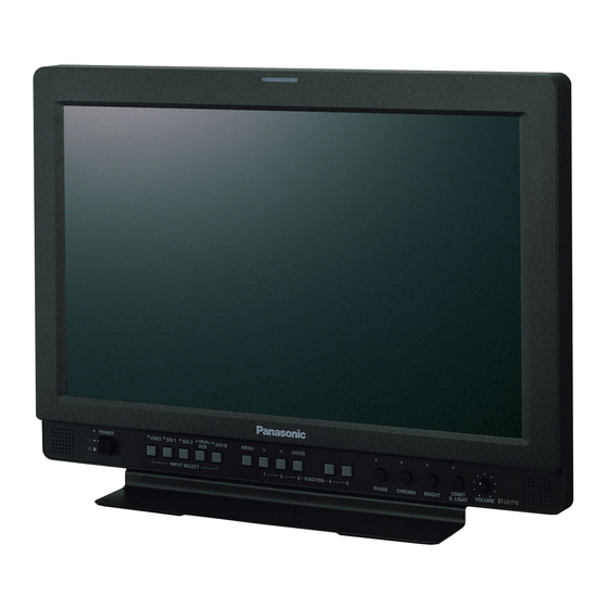
Outline The BT-LH1760/1710 LCD monitor was designed especially for broadcasting service and business use. It is equipped with a high performance 17.0-inch wide LCD display panel. ■ High performance LCD panel This monitor achieves outstanding color reproduction, a wide viewing angle, and high-speed response. The double-speed drive function has substantially reduced image lag (BT-LH1760 only). -
Page 8: Controls And Their Functions
Controls and Their Functions Video monitor unit Front view Tally ( page 29, 36) Front panel ( page 9) Rear view Rear panel ( page 10) Power supply [you can switch between AC and DC ( page 11)]... -
Page 9: Front Panel
Controls and Their Functions (continued) Front panel POWER switch Switches the power supply ON/OFF. When the power is ON, the LED (green) lights up. INPUT SELECT buttons Selects the signal input line. The green LED light above the button indicates the selected input signal. VIDEO Video input SDI1... -
Page 10: Rear Panel
Controls and Their Functions (continued) Rear panel SDI (HD/SD) terminal (BNC) : This is the SDI input terminal (compatible with HD/SD automatic switching). : This is the SDI input terminal (compatible with HD/SD automatic switching). SWITCHED OUT : This is the active through-out terminal for the SDI input signal being displayed on the screen. * SDI active through-out is only output when [SDI1] or [SDI2] is selected using the [INPUT SELECT] buttons. -
Page 11: Power Supply
Power Supply Connecting and fixing the power cord ■ When using external DC power (12V DC) 1. Attach the power cord to the monitor unit. You can slide open the power cover, and switch from AC input to external DC input. (When shipped from Using the power cord the factory, the power cover is up, and AC input is hook and the screw,... -
Page 12: How To Use The On Screen Menu
How to Use the On Screen Menu The screen displays eight types of information: input signal status, picture adjusting knob status, sharpness display, FUNCTION display, audio level meter display, menu display, time code display and closed caption display. Input signal status 1. - Page 13 How to Use the On Screen Menu (continued) FUNCTION display • Use the menu to open and set up functions. • When “FUNCTION DISPLAY” ( page 23) is set to press “FUNCTION1” “FUNCTION5” buttons to display the functions F1:MARKER assigned to the FUNCTION buttons. F2:WFM/VECTOR •...
- Page 14 How to Use the On Screen Menu (continued) Time code (TC) display • Use the menu to display the time code for HD-SDI signal input. It also allows you to switch display mode (VITC, LTC, VUB, LUB). In VITC and LTC display mode: •...
- Page 15 How to Use the On Screen Menu (continued) Menu operations 1. Press [MENU] to display the MAIN menu. 3. Press [ ] to select a sub menu and Press [ENTER]. The settings in the sub menu change to green. 2. Press [ ] to select a menu and press [ENTER].
-
Page 16: User Data
User Data You can save and load up to five combinations of menu settings and adjustments made with the picture adjustment knob as user data. You can also return settings and adjustments to their factory defaults. User data include the following settings. •... -
Page 17: Main Menu
Main Menu Menu configuration MAIN MENU MARKER MARKER 16:9 VIDEO CONFIG GAMMA SELECT FILM GAMMA CONT./BACK. BACK SYSTEM CONFIG COLOR TEMP. BACKLIGHT CENTER SHARPNESS MODE SUB WINDOW GPI PRESET1 SHARPNESS H MENU POSITION GPI PRESET2 SHARPNESS V STATUS DISPLAY MARKER TYPE I-P MODE SETUP LOAD CROSS HATCH... -
Page 18: Marker
MARKER TYPE TYPE2 <TYPE1> Conventional monitor marker size <TYPE2> Marker size compliant with the camera recorder (Panasonic) CROSS HATCH HIGH Turns the cross hatch grid on and off and sets its density. <HIGH> 70/256 (displays a dense cross hatch grid) <LOW>... -
Page 19: Marker Types
Main Menu (continued) Marker types ■ 16:9 marker ■ 4:3 marker (Displayed for SD input in 4:3 aspect ratio mode) (Displayed for HD input and SD input in 16:9 ratio This marker is displayed as a dotted line. mode.) This marker is only displayed as a vertical bar. The section becomes the “MARKER BACK”. -
Page 20: Video Config
Main Menu (continued) VIDEO CONFIG Underlined values indicate factory defaults. Sub menu Settings Description GAMMA STANDARD Selects gamma curve. *1*2 SELECT FILM <STANDARD> Standard mode <FILM> Film mode <STDIO/PST> Color emphasis mode (a mode that approximates CRT STDIO/PST display capability suitable for studio or postproduction application) mark appears at the top left of the screen when “FILM”... - Page 21 Main Menu (continued) IP mode “MODE1” performs IP conversion using inter-frame interpolation. Conventional inter-frame interpolation involved 1-frame or greater delay, but this monitor suppresses the delay to within 1 field. The factory default is “MODE1”. “MODE2” performs IP conversion using inter-field interpolation. Since interpolation is performed inside each field, this mode is suitable for checking interlace status.
-
Page 22: System Config
Main Menu (continued) SYSTEM CONFIG Underlined values indicate factory defaults. Sub menu Settings Description CONT./BACK. BACKLIGHT Selects function to be assigned to [CONTRAST/BACKLIGHT] (front panel CONTRAST knob). <BACKLIGHT> Adjusts the BACKLIGHT. <CONTRAST> Adjusts the CONTRAST. BACKLIGHT 0 - 60 Adjusts LCD backlight brightness. Adjust as required by ambient conditions. -
Page 23: Function
Main Menu (continued) FUNCTION Underlined values indicate factory defaults. Sub menu Settings Description FUNCTION 1 - HV DELAY Selects functions to be assigned to [FUNCTION1] - [FUNCTION5] FUNCTION 5 AUTOSETUP (front panel buttons). BLUE ONLY <HV DELAY> GAMMA SELECT Displays synchronizing signals (horizontal, vertical). SD ASPECT The display changes in the following order. - Page 24 Main Menu (continued) ■ FUNCTION setting restrictions Settings are not available under the following conditions. Setting Conditions that disable operation HV DELAY During SUB WINDOW, WFM, PIXEL TO PIXEL mode operation, “INVALID FUNCTION” appears to indicate that operation is disabled. When “RGB-COMP.”...
- Page 25 Main Menu (continued) ■ Functions displayed during FUNCTION button operation Pressing any of the [FUNCTION1] to [FUNCTION5] buttons displays the operations assigned to each button as shown below. • HV DELAY • MARKER DELAY OFF/V DELAY/H DELAY/HV DELAY MARKER OFF/4:3 MARKER/13:9 MARKER/14:9 •...
- Page 26 Main Menu (continued) • PART Resizes the main window to show only its center to also display a second image (two sub-windows). Press the FUNCTION button to which the SUB WINDOW function has been assigned. Normal window Before image input After image input (main window) (two sub-windows)
- Page 27 Main Menu (continued) ■ “PIXEL TO PIXEL” and “PIXEL POSITION” The “PIXEL TO PIXEL” function allows you to check images at their actual pixel resolution (1080I/P signals only). Press the button ([FUNCTION1] to [FUNCTION5] ( page 23)) to which the “PIXEL TO PIXEL” function has been assigned to turn the function on.
- Page 28 Main Menu (continued) ■ “CROSS HATCH” The “CROSS HATCH” function enables display of markers at regular vertical and horizontal intervals to facilitate composition and other tasks. The width of marker lines is 1 dot, the markers consist of 1 line, and are spaced 80 dots apart (fixed value).
-
Page 29: Gpi
Main Menu (continued) “GPI CONTROL” is used to enable and disable GPI functions and assign functions to each of the GPI terminal pins page 36). Underlined values indicate factory defaults. Sub menu Settings Description GPI CONTROL DISABLE Enables and disables GPI functions ENABLE <DISABLE>... -
Page 30: Input Select
Main Menu (continued) INPUT SELECT Underlined values indicate factory defaults. Sub menu Settings Description VIDEO AUTO Selects the video input format. NTSC <AUTO> Automatically selects NTSC or PAL. <NTSC> NTSC <PAL> PAL NTSC SETUP Selects NTSC setup level. <75> Select this function when using 7.5% setup signals. (Adjusts the interior of the monitor to the 7.5% setup level to suit the black level) <00>... - Page 31 Main Menu (continued) ■ COMP. Selecting “RGB-COMP.” under “YP /RGB” in the “INPUT SELECT” menu opens the following menu. Underlined values indicate factory defaults. Sub menu Settings Description AUTOSETUP Selecting “RGB-COMP.” under “YP /RGB” in the “INPUT SELECT” menu automatically adjusts the screen. A separate screen opens.
-
Page 32: Audio
Main Menu (continued) AUDIO Sets speaker and headphones output. Underlined values indicate factory defaults. Sub menu Settings Description INPUT AUTO Selects speaker and headphones output. SELECT ANALOG <AUTO> When an SDI input line is selected with the [INPUT SELECT] button on the front panel: embedded audio (SDI terminal) When input lines other than SDI1 or SDI2 are selected with the [INPUT SELECT] button on the front panel:... -
Page 33: Display Setup
Main Menu (continued) DISPLAY SETUP Underlined values indicate factory defaults. Sub menu Settings Description WFM/ Switches between “WFM/VECTOR” waveform and vector display. VECTOR <WFM> Displays waveforms. VECTOR <VECTOR> Displays vector waveforms. POSITION Selects the position for the “WFM/VECTOR” waveform display. <LB>... -
Page 34: Control
Main Menu (continued) CONTROL Underlined values indicate factory defaults. Sub menu Settings Description CONTROL LOCAL Selects operation. (with control clock) REMOTE <LOCAL> Enables front panel operation <REMOTE> Enables remote operation (front panel operation is locked) LOCAL DISABLE. Selects the disabled operation on the front panel when selecting INPUT “REMOTE”... - Page 35 Main Menu (continued) ■ List of setting restrictions ( × : available, : not available) Input SDI 1/2 RGB-VIDEO DVI-VIDEO VIDEO RGB-COMP. DVI-COMP. MARKER × × 16:9 × × × × BACK × × MARKER CENTER × × GPI PRESET1 ×...
-
Page 36: Remote Specifications
REMOTE Specifications This monitor permits remote operation via GPI/RS-232C terminal. GPI terminal GPI screen items correspond to the following terminals. Use the GPI menu to assign functions to each terminal ( page 29). Functions assigned to terminals are executed when GND (pin 5) is short-circuited (ON) or open (OFF). Pin number Signal ■... - Page 37 REMOTE Specifications (continued) ■ Priority of assigned functions • When both “MARKER1” and “MARKER2” are activated at the same time, “MARKER1” has priority. However, when the display aspect ratio is 4:3, the “MARKER1” aspect ratio is 16:9 and the “MARKER2” aspect ratio is 4:3, “MARKER2”...
- Page 38 REMOTE Specifications (continued) ■ Setting command No Command Description Data Response Input switch 0: SDI1 1: SDI2 2: VIDEO 3: YP /RGB 6: DVI-D Image quality CON00-60 : Contrast settings adjustment BRI00-60 : Brightness settings CRO00-60 : Chroma settings PHA00-60 : Phase settings Blue only 0: OFF 1: ON...
- Page 39 REMOTE Specifications (continued) ■ Query command Command Description Data Response Input selection 0: SDI1 1: SDI2 2: YP 3: RGB-VIDEO 4: VIDEO 6: RGB-COMP. 9: DVI-VIDEO 10: DVI-COMP. Image quality CON : Contrast setting value 00-60 adjustment : Brightness setting value 00-60 CRO : Chroma setting value 00-60...
-
Page 40: How To Attach The Rack Mount
How to Attach the Rack Mount The monitor can be fitted with an optional BT-MA1710G rack mount adaptor to enable mounting it in a standard 19- inch rack (7U size height). The steps below show how to attach it. 1. Remove the three screws on the back and base 2. -
Page 41: Error And Warning Displays
Error and Warning Displays If for any reason an error occurs in this monitor, the LEDs above the picture adjusting knob flash at 1-second intervals to inform of the error/warning. Error and Warning Symptom Remedy displays Inverter error If a malfunction occurs in the inverter that Turn off the power and then turn it back controls backlight brightness, the on. -
Page 42: Specifications
Specifications ■ General ■ Signal level Input power VIDEO EXT SYNC signal level: 0.3 Vp-p to 4.0 Vp-p Power supply: Power consumption: HD/VD signal level: TTL level 100 V - 240 V, 50/60 Hz 0.6 A - 0.3 A AUDIO 12 V (11 V - 17 V) 4.0 A AUDIO input level:... - Page 43 Specifications (continued) ■ List of compatible signal formats ( : Compatible, : Limited compatibility) Input signal formats VIDEO SDI1 SDI2 RGB-VIDEO RGB-COMP. DVI VIDEO DVI COMP. NTSC 480/59.94I 480/59.94P 576/50I 576/50P 720/50P 720/59.94P 720/60P 1035/59.94I 1035/60I 1080/23.98PsF 1080/24PsF 1080/23.98P 1080/24P 1080/25P 1080/29.97P 1080/30P...
- Page 44 Panasonic Broadcast & Television Systems Company Unit Company of Panasonic Corporation of North America Executive Office: One Panasonic Way 4E-7, Secaucus, NJ 07094 Tel: 201-348-7000 Eastern Zone: One Panasonic Way 4E-7, Secaucus, NJ 07094 Tel: 201-348-7196 Southeast Region: Tel: 201-392-6151 Western Zone: 3330 Cahuenga Blvd W., Los Angeles, CA 90068 Tel: 323-436-3608...