
Related Manuals for Panasonic BT-LH1760W


Summary of Contents for Panasonic BT-LH1760W
-
Page 1: Operating Instructions
Before operating this product, please read the instructions carefully and save this manual for future use. F0308T0 -P Printed in Japan Operating Instructions LCD Video Monitor BT-LH1760P Model No. BT-LH1760E Model No. ENGLISH VQT1R47... -
Page 2: Read This First
CAUTION: Operation at a voltage other than 120 V AC may require the use of a different AC plug. Please contact either a local or foreign Panasonic authorized service center for assistance in selecting an alternate AC plug. CAUTION: • Keep the temperature inside the rack to between 41°F to 95°F (5°C to 35°C). -
Page 3: Important Safety Instructions
Responsible Party: Panasonic Corporation of North America One Panasonic Way, Secaucus, NJ07094 Support contact: Panasonic Broadcast & Television Systems Company 1-800-524-1448 This device complies with Part 15 of FCC Rules. Operation is subject to the following two conditions: (1) This device may not cause harmful interference, and (2) this device must accept any interference received, including interference that may cause undesired operation. - Page 4 An improper installation could cause the monitor to fall off resulting in personal injury. CAUTION: Remove the wall mount adaptor when not used. Otherwise people moving in the vicinity of the monitor could get caught on the bracket and be injured...
-
Page 5: Transportation Precautions
(continued) FOR U.K. ONLY How to replace the fuse 1. Open the fuse compartment with a screwdriver. on the 2. Replace the fuse. Do not place the monitor face down during transportation to prevent damaging it. Keep it upright. Fuse... -
Page 6: Table Of Contents
Dimensions ....... . 7 Controls and Their Functions ....8 Video monitor unit ... 8 Front panel ... 9 Rear panel... -
Page 7: Outline
• Cross hatch overlay function Displays markers at regular vertical and horizontal intervals to facilitate composition. ■ REMOTE control Depending on the intended use of the monitor, you can select between parallel remote control (GPI) and serial remote control (RS232C). Dimensions Unit: mm (inches) 16(0.6) -
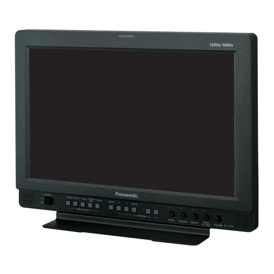
Page 8: Controls And Their Functions
Controls and Their Functions Video monitor unit Front view Front panel ( Rear view Tally ( page 29, 36) page 9) Rear panel ( page 10) Power supply [you can switch between AC and DC ( page 11)]... -
Page 9: Front Panel
When values are changed from the factory defaults, the LED above the knob (amber) lights. Settings are loaded when the monitor is turned on. The settings are saved when the knob is pressed, or when 10 seconds have elapsed after they have been changed. However, operating changes cannot be made in the following conditions. -
Page 10: Rear Panel
* SDI input audio is automatically selected by selecting [SDI1] or [SDI2] with [INPUT SELECT]. HEADPHONES output connector (Stereo mini-jack M3) Connect a pair of headphones to monitor the sound. * The sound volume and sound quality will depend on the headphones. Note that plugging in a pair of headphones turns off the speakers. -
Page 11: Power Supply
Power Supply Connecting and fixing the power cord 1. Attach the power cord to the monitor unit. Using the power cord hook and the screw, attach the power cord to the monitor unit. Power cord Power cord hook Screw 2. Connect the power cord to the power outlet. -
Page 12: How To Use The On Screen Menu
How to Use the On Screen Menu The screen displays eight types of information: input signal status, picture adjusting knob status, sharpness display, FUNCTION display, audio level meter display, menu display, time code display and closed caption display. Input signal status Picture adjusting knob status Sharpness display 1. - Page 13 How to Use the On Screen Menu FUNCTION display F1:MARKER F2:WFM/VECTOR F3:PIXEL TO PIXEL F4:TIME CODE F5:LEVEL METER XXXXX Audio level meter display Channel Level 0 dB line display display Menu display [MAIN MENU] Displays instructions on menu button operations. (continued) •...
- Page 14 How to Use the On Screen Menu Time code (TC) display Closed caption (CC) display (continued) • Use the menu to display the time code for HD-SDI signal input. It also allows you to switch display mode (VITC, LTC, VUB, LUB). In VITC and LTC display mode: •...
- Page 15 How to Use the On Screen Menu Menu operations 1. Press [MENU] to display the MAIN menu. 2. Press [ ] to select a menu and press [ENTER]. [MAIN MENU] To return to the previous screen Push [MENU]. (continued) 3. Press [ ] to select a sub menu and Press [ENTER].
-
Page 16: User Data
You can also return settings and adjustments to their factory defaults. User data include the following settings. • Menu settings except “SETUP LOAD/SAVE” (including button function settings on the monitor front panel) • Screen adjustments made with the picture adjusting knob Saving user data 1. -
Page 17: Main Menu
Main Menu Menu configuration MAIN MENU MARKER VIDEO CONFIG CONT./BACK. SYSTEM CONFIG BACKLIGHT SUB WINDOW MENU POSITION STATUS DISPLAY SETUP LOAD SETUP SAVE POWER ON SETUP COLOR SPACE POWER SAVE MODE BLACK DATA INSERTION FUNCTION1 FUNCTION FUNCTION2 FUNCTION3 FUNCTION4 FUNCTION5 FUNCTION DISPLAY INPUT SELECT VIDEO... -
Page 18: Marker
Selects conventional monitor or camera recorder marker size. <TYPE1> Conventional monitor marker size <TYPE2> Marker size compliant with the camera recorder (Panasonic) Turns the cross hatch grid on and off and sets its density. <HIGH> 70/256 (displays a dense cross hatch grid) <LOW>... -
Page 19: Marker Types
Main Menu (continued) Marker types ■ 16:9 marker (Displayed for HD input and SD input in 16:9 ratio mode.) This marker is only displayed as a vertical bar. The section becomes the “MARKER BACK”. 4:3 marker 14:9 marker VISTA marker, CNSCO marker This marker is displayed as a horizontal dotted line. -
Page 20: Video Config
Main Menu (continued) VIDEO CONFIG Sub menu Settings GAMMA STANDARD *1*2 SELECT FILM STDIO/PST VARICAM FILM GAMMA OTHER COLOR TEMP. USER0 - 63 VAR1 VAR2 VAR3 SHARPNESS HIGH MODE 0 - 30 SHARPNESS H 0 - 30 SHARPNESS V *2*6 MODE2 I-P MODE MODE1... - Page 21 (continued) IP mode “MODE1” performs IP conversion using inter-frame interpolation. Conventional inter-frame interpolation involved 1-frame or greater delay, but this monitor suppresses the delay to within 1 field. The factory default is “MODE1”. “MODE2” performs IP conversion using inter-field interpolation.
-
Page 22: System Config
BLACK DATA INSERTION *1 When the monitor is shipped, settings for “USER1” - “USER5” are identical to “FACTORY.” *2 “H-POSITION”, “V-POSITION”, “PHASE” and “CLOCK” ( *3 Double speed reduces image lag caused by black signal input but lowers resolution compared to standard speed and some images may generate flicker. -
Page 23: Function
Main Menu (continued) FUNCTION Sub menu Settings FUNCTION 1 - HV DELAY FUNCTION 5 AUTOSETUP BLUE ONLY GAMMA SELECT SD ASPECT SCAN SUB WINDOW WFM/VECTOR MARKER PIXEL TO PIXEL PIXEL POSITION LEVEL METER CROSS HATCH MONO TIME CODE CLOSED CAPTION UNDEF (Factory default: FUNCTION1:... - Page 24 Main Menu (continued) ■ FUNCTION setting restrictions Settings are not available under the following conditions. Setting Conditions that disable operation HV DELAY During SUB WINDOW, WFM, PIXEL TO PIXEL mode operation, “INVALID FUNCTION” appears to indicate that operation is disabled. When “RGB-COMP.”...
- Page 25 Main Menu (continued) ■ Functions displayed during FUNCTION button operation Pressing any of the [FUNCTION1] to [FUNCTION5] buttons displays the operations assigned to each button as shown below. • HV DELAY DELAY OFF/V DELAY/H DELAY/HV DELAY • AUTOSETUP AUTOSETUP/COMPLETE/INCOMPLETE/NOT RGB-COMP.CH •...
- Page 26 Main Menu (continued) • PART Resizes the main window to show only its center to also display a second image (two sub-windows). Press the FUNCTION button to which the SUB WINDOW function has been assigned. Normal window (main window) Press the button again Video Crops the image to show its...
- Page 27 Main Menu (continued) ■ “PIXEL TO PIXEL” and “PIXEL POSITION” The “PIXEL TO PIXEL” function allows you to check images at their actual pixel resolution (1080I/P signals only). Press the button ([FUNCTION1] to [FUNCTION5] ( been assigned to turn the function on. Then press the button ([FUNCTION1] to [FUNCTION5] ( which the “PIXEL POSITION”...
- Page 28 Main Menu (continued) ■ “CROSS HATCH” The “CROSS HATCH” function enables display of markers at regular vertical and horizontal intervals to facilitate composition and other tasks. The width of marker lines is 1 dot, the markers consist of 1 line, and are spaced 80 dots apart (fixed value).
-
Page 29: Gpi
Main Menu (continued) “GPI CONTROL” is used to enable and disable GPI functions and assign functions to each of the GPI terminal pins page 36). Sub menu Settings GPI CONTROL DISABLE ENABLE GPI1 - GPI8 UNDEF MARKER1 ON/OFF MARKER2 ON/OFF MARKER BACK HALF MARKER BACK... -
Page 30: Input Select
0.7 Vp-p at 100% chroma. <B75> Select this when connecting a Betacam or similar device with a setup function. (Adjusts the interior of the monitor to the 7.5% setup level to suit the black level) <B00> Select this when connecting a Betacam or similar device without a setup function. - Page 31 Main Menu (continued) ■ COMP. Selecting “RGB-COMP.” under “YP Sub menu Settings AUTOSETUP H POSITION 0 - 60 (Factory preset settings: 30) V POSITION 0 - 60 (Factory preset settings: 30) PHASE 0 - 31 (Factory preset settings: 16 CLOCK 700 - 1800 (Factory preset settings: WXGA/XGA...
-
Page 32: Audio
Main Menu (continued) AUDIO Sets speaker and headphones output. Sub menu Settings INPUT AUTO SELECT ANALOG EMBEDDED CH1 - CH8 SELECT L (Factory default: CH1) EMBEDDED CH1 - CH8 SELECT R (Factory default: CH2) LEVEL METER CH SELECT 0dB POINT CH INFO. -
Page 33: Display Setup
Main Menu (continued) DISPLAY SETUP Sub menu Settings WFM/ VECTOR VECTOR POSITION VECTOR × 8 MODE × 4 × 2 × 1 VECTOR 100% SCALE TIME CODE MODE SELECT VITC CLOSED CAPTION MODE SELECT *1 Available during HD-SDI input signals. *2 Available during VIDEO (NTSC) input. -
Page 34: Control
Main Menu (continued) CONTROL Sub menu Settings CONTROL LOCAL REMOTE LOCAL DISABLE. INPUT ENABLE *1 The menu can be displayed when the lock is engaged. Only “CONTROL/LOCAL ENABLE” menu items are available when the lock is engaged. The picture adjusting knob is disabled when the lock is engaged. The “LOCAL ENABLE”... - Page 35 Main Menu (continued) ■ List of setting restrictions ( Input VIDEO MARKER 16:9 BACK MARKER CENTER GPI PRESET1 GPI PRESET2 MARKER TYPE CROSS HATCH GAMMA SELECT FILM GAMMA COLOR TEMP. SHARPNESS MODE SHARPNESS H VIDEO SHARPNESS V CONFIG I-P MODE MONO ANAMO SD ASPECT...
-
Page 36: Remote Specifications
REMOTE Specifications This monitor permits remote operation via GPI/RS-232C terminal. GPI terminal GPI screen items correspond to the following terminals. Use the GPI menu to assign functions to each terminal ( page 29). Functions assigned to terminals are executed when GND (pin 5) is short-circuited (ON) or open (OFF). - Page 37 REMOTE Specifications ■ Priority of assigned functions • When both “MARKER1” and “MARKER2” are activated at the same time, “MARKER1” has priority. However, when the display aspect ratio is 4:3, the “MARKER1” aspect ratio is 16:9 and the “MARKER2” aspect ratio is 4:3, “MARKER2”...
- Page 38 REMOTE Specifications ■ Setting command No Command Description Input switch Image quality adjustment Blue only HV Delay Backlight Cross hatch Status display Analog mode SELECT Sync DVI-D mode Marker settings Gamma selection Color temperature settings Sharpness settings IP mode settings Monochrome settings SD aspect settings Scan settings...
- Page 39 REMOTE Specifications ■ Query command Command Description Input selection Image quality adjustment Blue only Backlight Cross hatch Marker Gamma Color temperature Sharpness IP mode Monochrome Aspect Scan Analog mode SELECT sync DVI-D mode Format Model *1 When both 16:9 and 4:3 markers are displayed, the 16:9 marker state is returned. (continued) Data 0: SDI1...
-
Page 40: How To Attach The Rack Mount
How to Attach the Rack Mount The monitor can be fitted with an optional BT-MA1710G rack mount adaptor to enable mounting it in a standard 19- inch rack (7U size height). The steps below show how to attach it. 1. Remove the three screws on the back and base 2. -
Page 41: Error And Warning Displays
Error and Warning Displays If for any reason an error occurs in this monitor, the LEDs above the picture adjusting knob flash at 1-second intervals to inform of the error/warning. Error and Warning displays Inverter error If a malfunction occurs in the inverter that... -
Page 42: Specifications
Specifications ■ General Input power Power supply: 100 V - 240 V, 50/60 Hz 12 V (11 V - 17 V) is the safety information. Dimensions: • Including stand 430 (W) mm × 323.5 (H) mm × 198 (D) mm (W) inches ×... - Page 43 Specifications (continued) ■ List of compatible signal formats ( Input signal formats VIDEO NTSC 480/59.94I 480/59.94P 576/50I 576/50P 720/50P 720/59.94P 720/60P 1035/59.94I 1035/60I 1080/23.98PsF 1080/24PsF 1080/23.98P 1080/24P 1080/25P 1080/29.97P 1080/30P 1080/50I 1080/50P 1080/59.94I 1080/60I 1080/59.94P 1080/60P 640 × 400 (70 Hz) 640 ×...
- Page 44 San Gabriel Industrial Park, 65th Infantry Ave., Km. 9.5, Carolina, Puerto Rico 00630 (787) 750-4300 Professional & Broadcast IT Systems Business Unit Europe Panasonic AVC Systems Europe a Division of Panasonic Marketing Europe GmbH Hagenauer Str. 43, 65203 Wiesbaden-Biebrich Deutschland Tel: 49-611-235-481...