Advertisement
Quick Links
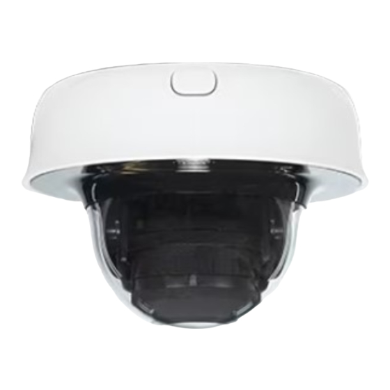
MV13 Installation Guide
Overview
The Cisco Meraki MV13 series are network cameras that are exceptionally simple to deploy and configure due to their
integration into the Meraki Dashboard and cloud-augmented edge storage. The MV family eliminates complex and costly
servers and video recorders required by traditional solutions, removing the limitations typically placed on video
surveillance deployments.
Package Contents:
In addition to the MV camera, the following are provided:
1
Advertisement

Related Manuals for Cisco Meraki MV13 Series


Summary of Contents for Cisco Meraki MV13 Series
- Page 1 MV13 Installation Guide Overview The Cisco Meraki MV13 series are network cameras that are exceptionally simple to deploy and configure due to their integration into the Meraki Dashboard and cloud-augmented edge storage. The MV family eliminates complex and costly servers and video recorders required by traditional solutions, removing the limitations typically placed on video surveillance deployments.
- Page 2 Unit MV13-HW Mounting Equipment 1 x T10 Torx key...
-
Page 3: Pre-Install Preparation
1 x Small Mounting Plate 1 x Conduit Adapter MV13 series does not ship with mounting screws and anchors as an included accessory in the packaging content. Screw Recommendation: • Type: Self-Tapping Screw • Size: M4 • Length: Minimum 25mm •... -
Page 4: Check And Configure Firewall Settings
2. Find the network to which you plan to add your cameras or create a new network. 3. Add your cameras to your network. You will need your Meraki order number (found on your invoice) or the serial number of each camera, which looks like Qxxx-xxxx-xxxx and is on the bottom of the unit. 4. - Page 5 Microphone Cut-off Switch & Factory Reset Button: The MV13 has a new microphone cut-off switch at the camera's base. This switch can be used to disable audio and override the Dashboard Audio Settings for an added layer of security. If the regulations require disabling audio or Dashboard control for Audio enablement needs to be disabled, the microphone cut-off switch can be leveraged and set to Disabled.
- Page 6 Installing the conduit box to MV13 series: (optional)
- Page 7 4. MV13 series comes with two base mount plates, a small plate and a large plate. The functionality of both plates is identical. Please refer to the guidelines below on using the base plate mounting to any surface or on top of a mounting accessory.
- Page 9 • Twist the camera while holding the button until a click is heard. • The camera is locked onto the plate and secured. • Remove the protective cover The MV13 Series cameras have a button to engage the locking mechanism. Press the button while aligning the MV13 series to the base plate.
- Page 10 6. Aim the lens. Look through the camera on the Meraki Dashboard to fine-tune the picture. The camera sensor and lens unit can be physically tilted through 65 degrees, rotated through a range of +/-90 degrees, and panned through 354 degrees.