Advertisement
Quick Links
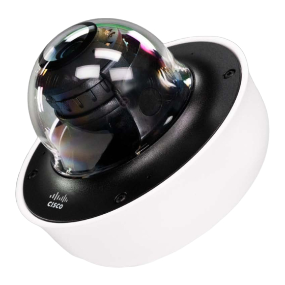
MV63 Installation Guide
MV63 Series Overview
The Cisco Meraki MV63 series are network cameras that are exceptionally simple to deploy and configure due to their integration into the Meraki Dashboard and
cloud-augmented edge storage. The MV family eliminates complex and costly servers and video recorders required by traditional solutions, removing the
limitations typically placed on video surveillance deployments.
Package Contents:
In addition to the MV camera, the following are provided:
1
Advertisement

Related Manuals for Cisco Meraki MV63


Summary of Contents for Cisco Meraki MV63
- Page 1 MV63 Series Overview The Cisco Meraki MV63 series are network cameras that are exceptionally simple to deploy and configure due to their integration into the Meraki Dashboard and cloud-augmented edge storage. The MV family eliminates complex and costly servers and video recorders required by traditional solutions, removing the limitations typically placed on video surveillance deployments.
- Page 2 MV63-HW Unit MV63X-HW 1 x T10 Torx key 2 x desiccant pack 1 x base mount plate small Mounting Equipment 1x base mount plate large 1x Decorative cover 1 x conduit adapter MV63 series does not ship with mounting screws and anchors as an included accessory in the packaging content. Screw Recommendation:...
-
Page 3: Pre-Install Preparation
• Type: Self-Tapping Screw • Size: M4 • Length: Minimum 25mm • Screw head diameter: Maximum 10mm • Driver Type: ANY (eg: Philips) • Head Type: ANY (Eg: Pan Head) • Build Material: Stainless Steel Note: The insertion diameter of the anchor should be smaller than that of the screw, and the length of the anchor should be longer than that of the screw. -
Page 4: Assigning Ip Addresses
Assigning IP Addresses Currently, the MV63 series camera does not support static IP assignment. MV63 units must be added to a subnet that uses DHCP and has available DHCP addresses to operate correctly. Installation Instructions Note: During first-time setup, the MV93 series will automatically update to the latest stable firmware. Some features may be unavailable until this automatic update is completed. - Page 6 Microphone Cut-off Switch: The MV63 Series has a new microphone cut-off switch at the camera's base. This switch can be used to disable audio and override the Dashboard Audio Settings for an added layer of security. If the regulations require disabling audio or Dashboard control for Audio enablement needs to be disabled, the microphone cut-off switch can be leveraged and set to Disabled.
- Page 7 2. Follow this in-depth cable gland assembly guide to connect the PoE cable to the camera cable gland and ensure the seal is water-tight. This step is very important and may damage the camera if done improperly. Note: If installing external conduit terminated at the camera, ensure the camera conduit adapter and terminal adapter are pulled over the camera pigtail before making the connection to avoid the risk of water damage leading to hardware failure and warranty void.
- Page 8 3. If using a conduit adapter, attach the terminal adapter to the conduit adapter. Route the conduit over the water-tight cable gland assembly and terminate at the terminal adapter. Ensure the camera conduit adapter is securely placed on the base mount plate as pictured.
- Page 9 Installing the conduit box to MV63 series: (optional) 4. MV63 series comes with two base mount plates, a small plate and a large plate. The functionality of both plates is identical. Please refer to the guidelines below on using the base plate mounting to any surface or on top of a mounting accessory.
- Page 10 MV63 Mount using small base plate: • Mount the small base plate onto the wall surface using the paper template provided. • Use 3x Wall anchor and screws to fix the base plate to the wall. • The MV63 Series cameras have a button to engage the locking mechanism. Press the button while aligning the MV63 series to the small base plate.
- Page 11 • Twist the camera while holding the button until a click is heard. • The camera is locked onto the plate and secured.
- Page 12 MV63 Mount using large base plate: • Mount the large base plate onto the wall surface using the paper template provided. • Use 4x Wall anchor and screws to fix the base plate to the wall. • The MV63 Series cameras have a button to engage the locking mechanism. Press the button while aligning the MV63 series to the large base plate.
- Page 13 • Twist the camera while holding the button until a click is heard. • The camera is locked onto the plate and secured.
- Page 14 MV63 Mount using the large base plate and Decorative Cover: • Mount the large base plate onto the wall surface using the paper template provided. • Use 4x Wall anchor and screws to fix the base plate to the wall. •...
- Page 15 • The MV63 Series cameras have a button to engage the locking mechanism. Press the button while aligning the MV63 series to the small base plate. • Twist the camera while holding the button until a click is heard.
- Page 16 • The camera is locked onto the plate and secured. 5. Once completed, twist and lock the camera to the base plate; a click is heard when the camera is locked. 6. Observe the status LED on the left side of the camera lens assembly and ensure the camera is connected via Ethernet (solid green) or WiFi (solid blue). An MV must first be provisioned over a wired Ethernet connection before it can be deployed wirelessly.
- Page 17 6. Aim the lens. Look through the camera on the Meraki Dashboard to fine-tune the picture. The camera sensor and lens unit can be physically tilted through 65 degrees, rotated through a range of +/-90 degrees, and panned through 354 degrees. The image can only be rotated by 180 degrees in software, and no other adjustments can be made.
- Page 18 7. Re-install the optical dome and completely secure all four Torx head security screws. Remove the protective plastic cover.