Advertisement
Quick Links
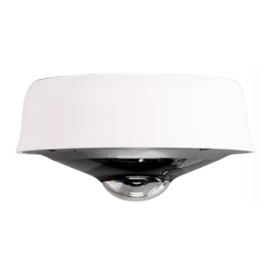
MV93 Series Installation Guide
MV93 Series Overview
The Cisco Meraki MV93 series MVs are the 3rd Generation network cameras that are exceptionally simple to deploy and configure due to their integration into
the Meraki Dashboard and cloud-augmented edge storage. The MV family eliminates complex and costly servers and video recorders required by traditional
solutions, removing the limitations on video surveillance deployments.
Package Contents:
In addition to the MV camera, the following are provided:
1
Advertisement

Related Manuals for Cisco Meraki MV93 Series


Summary of Contents for Cisco Meraki MV93 Series
- Page 1 MV93 Series Overview The Cisco Meraki MV93 series MVs are the 3rd Generation network cameras that are exceptionally simple to deploy and configure due to their integration into the Meraki Dashboard and cloud-augmented edge storage. The MV family eliminates complex and costly servers and video recorders required by traditional solutions, removing the limitations on video surveillance deployments.
- Page 2 MV93-HW Unit MV93X-HW 4 x wall anchors 4 x wall screws 1 x base mount plate small Mounting Equipment 1x base mount plate large 1x Decorative cover 1 x conduit adapter...
-
Page 3: Pre-Install Preparation
Powering the MV93 Series The MV93 features a 1000BASE-TX Ethernet port and requires 802.3at PoE+ minimally for operation. Route the Ethernet cable from an active port on a PoE switch or injector. Note: Power over Ethernet supports a maximum cable length of 300 ft (100 m). Pre-Install Preparation You should complete the following steps before going on-site to perform an installation: Configure Your Network in the Dashboard... -
Page 4: Mounting Instructions
Mounting Instructions For most mounting scenarios, the MV93 wall mount provides a quick, simple, and flexible means for mounting your device. The installation should be done in a few simple steps: Note: Leave the protective plastic cover on the optical dome throughout the installation process to prevent any damage to the dome. The protective cover should be removed once the installation process is completed. - Page 5 Note: If the microphone switch is disabled and the camera is mounted, toggling the switch back ON would require accessing the camera's base. 1. Use the template to determine mounting hole locations for wall mounting before screwing in the base mount plate. Peel backing from the mounting template to stick on the wall.
- Page 6 2. Follow this in-depth cable gland assembly guide to connect the PoE cable to the camera cable gland and ensure the seal is water-tight. This step is very important and may damage the camera if done improperly. Note: If installing external conduit terminated at the camera, ensure the camera conduit adapter and terminal adapter are pulled over the camera pigtail before making the connection to avoid the risk of water damage leading to hardware failure and warranty void.
- Page 7 2. If using a conduit adapter, attach the terminal adapter to the conduit adapter. Route the conduit over the water-tight cable gland assembly and terminate at the terminal adapter. Ensure the camera conduit adapter is securely placed on the base mount plate as pictured.
- Page 8 Installing the conduit box to MV93 series: (optional) 3. MV63 series comes with two base mount plates, a small plate and a large plate. The functionality of both plates is identical. Please refer to the guidelines below on using the base plate mounting to any surface or on top of a mounting accessory.
- Page 9 MV93 Mount using small base plate: • Mount the small base plate onto the wall surface using the paper template provided. • Use 3x Wall anchor and screws to fix the base plate to the wall. • The MV93 Series cameras have a button to engage the locking mechanism. Press the button while aligning the MV93 series to the small base plate.
- Page 10 • Twist the camera while holding the button until a click is heard. • The camera is locked onto the plate and secured.
- Page 11 MV93 Mount using large base plate: • Mount the large base plate onto the wall surface using the paper template provided. • Use 4x Wall anchor and screws to fix the base plate to the wall. • The MV93 Series cameras have a button to engage the locking mechanism. Press the button while aligning the MV93 series to the large base plate.
- Page 12 • Twist the camera while holding the button until a click is heard. • The camera is locked onto the plate and secured.
- Page 13 MV93 Mount using large base plate and Decorative Cover: • Mount the large base plate onto the wall surface using the paper template provided. • Use 4x Wall anchor and screws to fix the base plate to the wall. • Place the decorative cover on top of the large base plate and press the cover against the plate.
- Page 14 • The MV93 series cameras have a button to engage the locking mechanism. Press the button while aligning the MV93 series to the small base plate. • Twist the camera while holding the button until a click is heard.
- Page 15 • The camera is locked onto the plate and secured. 4. Once completed, twist and lock the camera to the base plate. A click is heard when the camera is locked in place. Remove the protective cover when the installation is complete. 5.