Cisco PVC2300 Administration Manual
Internet video cameras with audio
Hide thumbs
Also See for PVC2300:
- Quick start manual ,
- Datasheet (6 pages) ,
- Reference manual (85 pages)

Related Manuals for Cisco PVC2300


Summary of Contents for Cisco PVC2300
- Page 1 ADMINISTRATION GUIDE Cisco Small Business PVC2300 and WVC2300 Internet Video Cameras with Audio...
- Page 2 Cisco TelePresence, Cisco Unified Computing System, Cisco WebEx, DCE, Flip Channels, Flip for Good, Flip Mino, Flip Video, Flip Video (Design), Flipshare (Design), Flip Ultra, and Welcome to the Human Network are trademarks; Changing the Way We Work, Live, Play, and Learn, Cisco Store, and Flip Gift Card are service marks; and Access Registrar,...
-
Page 3: Table Of Contents
Back Panel Antenna Connectors Reset Ethernet Activity LED PVC2300 PoE LED Power GPIO Mic In Spkr Out Side Panel Chapter 4: Connecting the Camera Cisco Wired Network Cisco Wireless Network Cisco PVC2300 and WVC2300 Internet Video Cameras with Audio Administration Guide... - Page 4 Log Out About Help Video Options Icons Setup Chapter 8: Configuring the PVC2300 and WVC2300 Cameras Accessing the Setup Options Setup > Basic Setup Device Settings Network Settings Wireless Settings Cisco PVC2300 and WVC2300 Internet Video Cameras with Audio Administration Guide...
- Page 5 Firmware Upgrade Audio/Video > Video MPEG-4 Settings MJPEG Settings Mobile Settings Video Adjustments Options Day/Night Switch Audio/Video > Audio Audio Settings Applications > Mail Primary SMTP Server Secondary SMTP Cisco PVC2300 and WVC2300 Internet Video Cameras with Audio Administration Guide...
- Page 6 Output Ports Manual Control Applications > RS-485 Port Settings Preset Position Patrol Sequence Applications > SMB/CIFS Status > System Status > Image MPEG-4 MJPEG Status > Network Network Wireless Cisco PVC2300 and WVC2300 Internet Video Cameras with Audio Administration Guide...
- Page 7 Appendix A: Troubleshooting Questions and Answers Windows Help TCP/IP Shared Resources Network Neighborhood/My Network Places Appendix B: WVC2300 Camera Bandwidth Test Appendix C: Specifications PVC2300 Specifications WVC2300 Specifications I/O Port Specifications Cisco PVC2300 and WVC2300 Internet Video Cameras with Audio Administration Guide...
- Page 8 Contents Appendix D: Where to Go From Here Cisco PVC2300 and WVC2300 Internet Video Cameras with Audio Administration Guide...
-
Page 9: Chapter 1: Introduction
The Cisco camera surveillance solutions are high quality solutions which can be optimized for many different applications. The box-type form factor allows these cameras to be used as-is or put inside an outdoor enclosure for interior or exterior applications. The cameras use removable CS-mount lenses and can be customized with Zoom, Wide-Angled, Vari-focal, Auto-Iris (DC type), or other type of lenses as required for the specific application. -
Page 10: Minimum Requirements
3G phones and Quicktime clients on PCs or Wi-Fi phones. Support for multiple network protocols like 802. 1 p priority, 802. 1 q VLANs, and Dynamic DNS, make the solution ideal for multiple IP surveillance applications. The cameras can also be managed securely using HTTPS. -
Page 11: Camera Lens Specifications
NVidia high performance or equivalent with a minimum 256 MB Browser Internet Explorer 6.0 (or later) or Mozilla Firefox More than eight cameras can be monitored if you reduce the resolution and frame NOTE rate settings for the video captures. The resolution and video quality can be adjusted from the Audio/Video >... - Page 12 Introduction Camera Lens Specifications For more information about camera accessories, see the Cisco Small Business Camera Accessories Installation and Administration Guide. Cisco PVC2300 and WVC2300 Internet Video Cameras with Audio Administration Guide...
-
Page 13: Chapter 2: Planning Your Wireless Network
If the computers on the wireless network need to be accessed by a wired network or need to share a peripheral, such as a printer, with the wired network computers, the wireless network should be set up in infrastructure mode. The basis of infrastructure mode centers around an access point, which serves as the main point of communications in a wireless network. -
Page 14: Wireless Network Layout
Planning Your Wireless Network Wireless Network Layout If the wireless network is relatively small and needs to share resources only with the other computers on the wireless network, then the ad-hoc mode can be used. Ad-hoc mode allows computers equipped with wireless transmitters and receivers to communicate directly with each other, eliminating the need for an access point. -
Page 15: Security Threats Facing Wireless Networks
WVC2300” on page 120. Wireless networks are easy to find. Hackers know that in order to join a wireless network, wireless networking products first listen for “beacon messages.” These messages can be easily decrypted and contain much of the network’s information, such as the network’s SSID (Service Set Identifier). - Page 16 Planning Your Wireless Network Security Threats Facing Wireless Networks WEP Encryption. Wired Equivalent Privacy (WEP) is often looked upon as a cure-all for wireless security concerns. This is overstating WEP’s ability. Again, this can only provide enough security to make a hacker’s job more difficult. There are several ways that WEP can be maximized: •...
-
Page 17: Chapter 3: Getting To Know The Pvc2300 And Wvc2300 Cameras
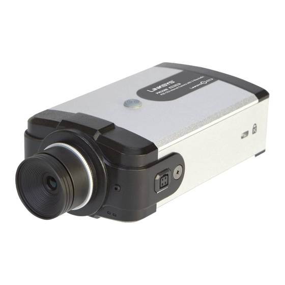
Front Panel, page 9 • Back Panel, page 11 • Side Panel, page 14 Front Panel The LEDs, camera lens, and built-in microphone are located on the front panel of the camera. Cisco PVC2300 and WVC2300 Internet Video Cameras with Audio Administration Guide... -
Page 18: Ready Led (Amber)
• Off—Camera is powered off. • On—Camera is powered on. • Flashing—The Ready LED will flash during start up. This will take 15 to 20 seconds. Network LED (Green) The Network LED has the following states: • Off—Network connection not detected. -
Page 19: Back Panel
Getting to Know the PVC2300 and WVC2300 Cameras Back Panel Back Panel The ports and reset button are located on the back panel of the camera.The following shows the back panel of the PVC2300. The following shows the back panel of the WVC2300. -
Page 20: Reset
Restore Factory Defaults—To restore the factory default settings, press the Reset button for more than 10 seconds. When you let go of the button, the LEDs on the front of the camera will flash and then return to a normal state when the camera is ready. -
Page 21: Activity Led
On the back panel, the green LED is the PoE indicator and when on, indicates that you have PoE power. If you plug in the power supply, this LED will not light up. Another good indicator is if you happen to plug in both the PoE and regular power supply, if the green LED is on, this indicates you have PoE power and if not, it indicates you have lost power from your PoE switch. -
Page 22: Power
This jack is used to connect powered speakers to the camera. Side Panel The security slot is located on a side panel of the camera and can be used to attach a Kensington lock. Cisco PVC2300 and WVC2300 Internet Video Cameras with Audio Administration Guide... -
Page 23: Chapter 4: Connecting The Camera
Connecting the Camera This chapter will guide you through the hardware installation for the Cisco PVC2300 and WVC2300 Internet Video Cameras. There are procedures for installing the camera into a wired or wireless network. The following sections are included: •... -
Page 24: Cisco Wired Network
Connecting the Camera Cisco Wired Network Cisco Wired Network The following illustration provides an example of a Cisco wired network: Cisco PVC2300 and WVC2300 Internet Video Cameras with Audio Administration Guide... -
Page 25: Cisco Wireless Network
Connecting the Camera Cisco Wireless Network Cisco Wireless Network The following illustration provides an example of a Cisco wireless network: Cisco PVC2300 and WVC2300 Internet Video Cameras with Audio Administration Guide... -
Page 26: Camera Installation Guidelines
• If using the microphone in the camera, note that the cameras are designed to pick up audio from a distance (unlike a web camera that you would place near you.) • If using an external microphone or speaker, place the microphone far enough away from the speaker to avoid feedback. - Page 27 Attach the swivel head directly to the stand base. • If an extension is necessary, attach the camera extension to the stand base and then attach the swivel head to the extension. Connect the camera stand to the bottom of the camera.
- Page 28 Connect the other end of the cable to the camera Ethernet port. STEP 6 If your network switch provides Power over Ethernet (PoE), proceed to step 8. If you NOTE are not sure if the switch provides PoE, refer to the switch documentation.
- Page 29 Camera Hardware Installation If your network switch does not provide PoE, connect the included power adapter STEP 7 to the Power port of the camera and insert the other end into a standard electrical outlet. Verify that the camera LEDs are lit.
-
Page 30: Adjusting The Lens
If you are installing the PVC2300 camera, you are done with the camera installation. NOTE However, if you are installing the WVC2300 camera, proceed to the next step. Connect each of the two antennas to the antenna connectors on the back of the STEP 9 camera. -
Page 31: Audio Options
The microphone you use must have its own source of power, like your computer NOTE speakers. Connect the 3.5 mm input jack of your microphone to the MIC IN port on the STEP 1 camera’s back panel. The built-in microphone will automatically be disabled. -
Page 32: Chapter 5: Installing The Camera Software
Setup Wizard that is included on the product CD. There are two ways to use the Setup Wizard: 1. Launch the Setup Wizard from the CD. Launching from the CD is useful if you do not want to install the software on your computer. - Page 33 Configuring the Basic Camera and Network Settings To configure the basic camera and network settings, follow these steps: Insert the Setup CD into your CD-ROM drive. If the CD doesn’t run automatically, go STEP 1 to My Computer and click on your CD-ROM drive.
- Page 34 Configuring the Basic Camera and Network Settings The License Agreement window appears. Click Next if you agree. STEP 3 The Wizard searches your network for your camera and displays a list of all STEP 4 cameras found. Cisco PVC2300 and WVC2300 Internet Video Cameras with Audio Administration Guide...
- Page 35 From the Camera Discovery window, highlight the camera you want to configure STEP 5 and click Next. If the camera you want to configure is not displayed in the Selection box, enable UPnP on your computer as described in Appendix A, “Troubleshooting”...
- Page 36 When prompted, type admin in both the Administrator Name and Administrator STEP 6 Password fields. The default user name and password is admin. Click OK. For security purposes, it is recommended that you change the password using the NOTE camera’s web-based utility at a later time. See “Administration >...
- Page 37 From the Basic Settings window, configure the following settings: STEP 7 • Camera Name—Enter a unique name for the camera, up to 16 characters in length. Unique names are helpful when you are using multiple cameras on the same network.
- Page 38 In the Network Settings window, select Static IP address from the drop-down list STEP 9 if you want to assign the IP address. Otherwise, leave the default setting as Obtain An IP Address Automatically (DHCP) and click Next. Cisco PVC2300 and WVC2300 Internet Video Cameras with Audio Administration Guide...
- Page 39 Installing the Camera Software Configuring the Basic Camera and Network Settings The current settings of the camera are displayed. Make any changes needed for STEP 10 your network and click Next. Cisco PVC2300 and WVC2300 Internet Video Cameras with Audio Administration Guide...
- Page 40 Installing the Camera Software Configuring the Basic Camera and Network Settings From the Review Camera Settings window, click Next to confirm the settings or STEP 11 click Back to make changes. Cisco PVC2300 and WVC2300 Internet Video Cameras with Audio Administration Guide...
- Page 41 Installing the Camera Software Configuring the Basic Camera and Network Settings From the Confirm Settings window, click OK to continue or Cancel to close the STEP 12 Confirm Settings window. When Cancel is clicked, you can click Back to make changes.
- Page 42 Installing the Camera Software Configuring the Basic Camera and Network Settings When OK is clicked, the new settings are saved. Cisco PVC2300 and WVC2300 Internet Video Cameras with Audio Administration Guide...
- Page 43 Installing the Camera Software Configuring the Basic Camera and Network Settings A dialog box appears indicating that the configuration has been saved STEP 13 successfully. Click OK to continue. Cisco PVC2300 and WVC2300 Internet Video Cameras with Audio Administration Guide...
- Page 44 Installing the Camera Software Configuring the Basic Camera and Network Settings Congratulations! Your camera is now configured. Click Finish to complete the STEP 14 process. The PVC2300 or WVC2300 Internet Camera Home window launches. STEP 15 Cisco PVC2300 and WVC2300 Internet Video Cameras with Audio Administration Guide...
- Page 45 Installing the Camera Software Configuring the Basic Camera and Network Settings When prompted, enter admin in both the User name and Password fields on the STEP 16 login window. The default username and password is admin. Internet Explorer prompts you to install ActiveX. In order to view video, you must STEP 17 accept the ActiveX.
- Page 46 Installing the Camera Software Configuring the Basic Camera and Network Settings Click Install ActiveX Control. STEP 18 Click Install. STEP 19 Cisco PVC2300 and WVC2300 Internet Video Cameras with Audio Administration Guide...
-
Page 47: Setting Up The Wireless Connection On The Wvc2300 Camera
Setting Up the Wireless Connection on the WVC2300 Camera To configure the WVC2300 camera for wireless connectivity, follow these steps: Click Setup in the toolbar to open the Setup > Basic Setup window. STEP 1 Enter the appropriate Wireless Settings: STEP 2 •... - Page 48 Installing the Camera Software Setting Up the Wireless Connection on the WVC2300 Camera • Channel No—If the camera is set to ad-hoc mode, select its channel setting from the drop-down list. When using Infrastructure mode, the channel setting is configured automatically.
- Page 49 Setting Up the Wireless Connection on the WVC2300 Camera The following describes the settings for each Security Mode option. • TX Key—Select the number of the key used for the wireless network. • WEP Encryption—Select the appropriate option for key length based on your network settings.
- Page 50 Shared Key—Enter the shared key used for accessing the wireless network. WPA /WPA2 Enterprise The options vary depending on the protocol type selected. • Protocol Type—Select EAP-TLS or EAP-TTLS. Cisco PVC2300 and WVC2300 Internet Video Cameras with Audio Administration Guide...
- Page 51 User CA—A user certificate is a signed private key certificate, which implies that you trust your browser’s publisher to include correct user certificates and in turn the certificate authorities it trusts, and anyone to whom the CA may have issued a certificate-issuing-certificate, to faithfully authenticate the users of all their certificates.
- Page 52 Click Save to save the wireless security settings and close the window. STEP 4 From the Setup > Basic Setup window, click Save to save the wireless settings. STEP 5 Cisco PVC2300 and WVC2300 Internet Video Cameras with Audio Administration Guide...
- Page 53 STEP 6 Disconnect the Ethernet cable from the camera. STEP 7 The wireless connection will not work if an Ethernet cable is attached to the camera NOTE when it is powered on. Cisco PVC2300 and WVC2300 Internet Video Cameras with Audio Administration Guide...
-
Page 54: Wired And Wireless Modes
NOTE After the initial configuration, you can use the camera in one of two modes: wired or wireless. Verify the mode you are in by viewing the LEDs. You cannot use the camera in both modes simultaneously. To switch between wired and wireless modes, see “Moving the Camera to... - Page 55 Installing the Camera Software Moving the Camera to Another Network To move the camera from a wireless network to a wired network, follow these steps: Unplug the power adapter from the camera. STEP 1 Connect the Ethernet network cable to your PC, router, or switch.
-
Page 56: Chapter 6: Upgrading The Camera Firmware
In the Address field, enter 192.168.1.99 and press Enter. STEP 2 The web-based utility login window appears. If this is your first time accessing the web-based utility, follow these steps at the STEP 3 login window: a. Enter admin in the User name field. - Page 57 Click Administration > Firmware. The current version is displayed. STEP 5 Click Upgrade. STEP 6 From the Upgrade Firmware window, click Browse to locate the firmware file. STEP 7 Click Upgrade and follow the on-screen instructions. STEP 8 Cisco PVC2300 and WVC2300 Internet Video Cameras with Audio Administration Guide...
- Page 58 Cisco recommends that you upgrade the camera’s firmware within your network. NOTE In other words, use a computer within the camera’s local network. If you attempt to upgrade the camera’s firmware from a remote location—using a computer outside of the camera’s local network—the upgrade may fail.
-
Page 59: Chapter 7: Using The Web-Based Configuration Utility
Setup, page 57 Launching the Web-Based Configuration Utility By default, the cameras are set to receive an IP address from a DHCP server. If you do not have a DHCP server on your network, you can set a static IP address by pressing the Reset button on the camera for less than three seconds. -
Page 60: Home
Using the Web-Based Configuration Utility Home If this is your first time accessing the web-based utility, follow these steps at the STEP 3 login window: a. Enter admin in the User name field. b. Enter admin in the Password field. -
Page 61: Setup
Connected User Displays the number of users. The maximum number of users is 10. Also, there are 10 video streams available for MJPEG and MPEG-4 in any combination, for example 5/5, 6/4, 7/3, 8/2, or 9/1. Log Out Log out from viewing the camera image. -
Page 62: Help
The camera software includes detailed Help files for all configuration tasks. To view a Help page, click the Help link in the top right corner of the window. A new window appears with information about the task that you are currently viewing. -
Page 63: Video Options Icons
Using the Web-Based Configuration Utility Home Video Options Icons The video options icons on the Home window are used to control the real-time view of your camera. The icons allow you to control the basic functions of the PVC2300 or WVC2300 cameras. Icon Description Click to turn on the selected output. - Page 64 Pelco D protocol device for the Move Control to work. Resolution Select the desired resolution from the drop-down list. The options are AUTO, 640 x 480, 320 x 240, 160 x 120. The default is AUTO and lets the camera determine the resolution. Zoom Click zoom and then drag your mouse to select the section you want to magnify.
-
Page 65: Setup
Streaming Video Set the video format to either MPEG-4 or MJPEG. Format Setup To access the setup options for the cameras, click Setup in the toolbar. For more information about Setup, see Chapter 8, “Configuring the PVC2300 and WVC2300 Cameras.”... -
Page 66: Chapter 8: Configuring The Pvc2300 And Wvc2300 Cameras
Configuring the PVC2300 and WVC2300 Cameras This chapter describes how to configure the Cisco PVC2300 and WVC2300 Internet Video Cameras using the web-based configuration utility. The following sections are included: • Accessing the Setup Options, page 59 • Setup > Basic Setup, page 59 •... -
Page 67: Accessing The Setup Options
Setup > Basic Setup The Setup > Basic Setup window displays the current device and network settings. If you are viewing the Setup > Basic Setup window of the WVC2300, the wireless NOTE settings are displayed also. See “Wireless Settings” on page... -
Page 68: Device Settings
Current Date/Time—Displays the current date and time. Click Change to modify the time settings. To change the current date and time, uncheck the check box Check here if you NOTE want to update the time automatically through the NTP Server on the Internet. - Page 69 NTP Server Address—Enter the address of the NTP Server. • NTP Port—The default NTP port is 123. If using a different port, enter the NTP port number (1024 to 65535) in the field provided. Cisco PVC2300 and WVC2300 Internet Video Cameras with Audio Administration Guide...
-
Page 70: Network Settings
Configuring the PVC2300 and WVC2300 Cameras Setup > Basic Setup If connecting to a router, it may be necessary to enable port forwarding. See NOTE “Configuring Port Forwarding” on page 117. Network Settings • Configuration Type—From the drop-down list, choose the configuration type: Fixed IP Address—Use this option to assign a fixed (static) IP address... - Page 71 Channel No—If the camera is set to Ad-hoc mode, select the appropriate channel from the list provided to correspond with your network settings. All devices in your wireless network must use the same channel in order to function correctly. In Infrastructure mode, you cannot specify a channel setting on the camera.
- Page 72 WPA /WPA2 Personal This security mode option offers two encryption methods, TKIP and AES, with dynamic encryption keys. Enter the Shared Key, which can have 8 to 63 characters. Then enter the Key Renewal Timeout, which instructs the device how often it should change the encryption keys.
- Page 73 Protocol Type—Select EAP-TLS or EAP-TTLS. EAP-TLS With EAP-TLS you enter the user ID and password for the RADIUS server and choose where the camera should check for the server and user certificate. Cisco PVC2300 and WVC2300 Internet Video Cameras with Audio Administration Guide...
- Page 74 User ID—User ID is used to login to your RADIUS server. • Root CA—A root certificate is an unsigned public key certificate, or a self- signed certificate, which implies that you trust your browser’s publisher to include correct root certificates and in turn the certificate authorities it trusts, and anyone to whom the CA may have issued a certificate-issuing- certificate, to faithfully authenticate the users of all their certificates.
- Page 75 EAP-TTLS With EAP-TTLS you choose the authentication protocol (MS-CHAP V2, MS-CHAP, PAP, EAP-MD5) to transfer the CA to the RADIUS server. You will also enter the User ID, Password, and Anonymous ID for the RADIUS server and choose where the camera should check for the server certificate.
-
Page 76: Setup > Advance Setup
The port number must be specified in the URL when accessing the camera’s web-based utility via the LAN or Internet. For example, if the camera’s IP address is 192. 1 68. 1 .99 and the port is defined as 1028, you would specify the following address: http://192. 1 68. 1 .99:1028. -
Page 77: Rtp/Rtsp
The port number must be specified in the URL when accessing the camera’s web-based utility via the LAN or Internet. For example, if the camera’s IP address is 192. 1 68. 1 .99 and the port is defined as 1032, you would specify the following address: https://192. 1 68. 1 .99:1032. -
Page 78: Upnp
A value in the range of 1 to 255 can be defined. The default value is 16. UPnP •... -
Page 79: Bonjour
Enable UPnP Traversal (Port Mapping)—When enabled will create a port forwarding rule on a NAT router automatically for opened HTTP, HTTPS, RTP, and RTPS ports. UPnP must be enabled on the NAT router for the Enable Traversal feature to NOTE work. -
Page 80: Setup > Ip Filter
Setup > IP Filter From the Setup > IP Filter window, you can configure IP Filter Settings to deny or allow camera access to a specific IP address or range of IP addresses. -
Page 81: Administration > Users
Enable and Allow the Following IP Address—Allows only the IP addresses specified access to the camera. From the drop-down list, select Single to enter a specific IP address or Range to enter a range of IP addresses. Up to 10 values can be configured. -
Page 82: Demo
Viewer—Provides the specified user video viewing privileges only. Click Add to add a new user ID or click Delete to remove an existing user ID. Click Save to save the user configuration. Cisco PVC2300 and WVC2300 Internet Video Cameras with Audio Administration Guide... -
Page 83: Administration > Maintenance
Administration > Users Administration > Maintenance From the Administration > Maintenance window, you can restore factory defaults, restart the camera, save the configuration settings, or upload a configuration file. Restore Factory Defaults • Restore—Restores the camera to the factory default settings. -
Page 84: Administration > Firmware
Configuring the PVC2300 and WVC2300 Cameras Administration > Firmware Administration > Firmware The Administration > Firmware window allows you to upgrade the firmware. Firmware Upgrade • Upgrade—Update the camera’s firmware. For more information, see Chapter 6, “Upgrading the Camera Firmware.”... -
Page 85: Audio/Video > Video
MPEG-4 Settings MPEG is the designation for a group of audio and video coding standards and related technology agreed upon by the ISO/IEC. The primary uses for the MPEG-4 standard are web (streaming media), CD distribution, and broadcast television. -
Page 86: Mjpeg Settings
Max Frame Rate—Select the desired maximum frame rate. The default value is 30 fps. MJPEG Settings MJPEG (Motion JPEG) is a video codec where each video field (frame) is separately compressed into a JPEG image. • Resolution—Select the desired video resolution format. The default resolution is 320x240. -
Page 87: Options
Cisco logo or user defined image. The upper left corner value is 0, 0. Increasing the X value (X: 0 - 639) will move the image to the right. Increasing the Y value (Y: 0 - 479) will move the image down. -
Page 88: Day/Night Switch
To use the camera in locations with poor lighting or at night, the IR-cut filter can be manually turned off or a schedule can be used to turn off the filter at a set time. An infrared lamp can be used to improve illumination in night surveillance applications without producing any extra visible light. -
Page 89: Audio Settings
Enable Audio—Enable audio by checking the Enable Audio check box. When audio is enabled, an icon is displayed on the Home window and audio is picked up through the camera. You can use the icons to turn audio on and off. - Page 90 Enable Speaker—When the speaker is enabled, an icon is displayed on the Home window. You can use the icons to turn the speaker on and off. The check box is auto-checked depending on the audio mode you set. If you set the audio mode to Simplex (Listen Only), then the check box is auto- checked.
-
Page 91: Applications > Mail
From the Applications > Mail window, you can configure and test primary and secondary SMTP servers. You can also configure the e-mail setup. Only one SMTP server is used, even if both the primary and secondary SMTP NOTE servers are enabled. The secondary SMTP server is used if the camera cannot connect to the primary server. -
Page 92: Secondary Smtp
SMTP server if the camera cannot connect to the primary SMTP server. • SMTP Mail Server—Enter the address of the Simple Mail Transport Protocol (SMTP) server to be used to send e-mail. You can use the IP address or the domain name. •... -
Page 93: E-Mail Setup
• Password—Enter the password associated with the account name. • POP Server Name—Enter the name of the POP3 mail server that is being used to receive e-mail. • Test SMTP Server—Click to test the configuration. You will get an error message if the transaction does not complete. -
Page 94: Applications > Ftp
From the Applications > FTP window, you can configure a primary and secondary FTP server. Only one FTP server is used, even if both the primary and secondary FTP servers NOTE are enabled. The secondary FTP server is used if the camera cannot connect to the primary server. -
Page 95: Secondary Ftp
• Enable Passive Mode—Check the box to enable the passive mode feature. Passive mode is a more secure form of data transfer. The use of passive FTP ensures all data flow initiation comes from inside the network rather than from the outside. -
Page 96: Applications > Instant Messaging
Presence Protocol (XMPP) and geared to provide message exchange in real time between two points on the Internet. Jabber is similar to IM systems such as AIM, ICQ and MSN but is open source, extensible through XML, and decentralized (allowing anyone to run a Jabber server). -
Page 97: Applications > Motion Detection
Applications > Motion Detection Applications > Motion Detection From the Applications > Motion Detection window, you can set the area(s) of the video image to be examined and adjust the sensitivity of detection for each area. Motion detection cannot be configured using the Firefox browser. Internet Explorer NOTE must be used to configure motion detection. - Page 98 Configuring the PVC2300 and WVC2300 Cameras Applications > Motion Detection • Full Screen—Enable this option to detect motion events within the full view of the screen. Indicator—Displays the level of motion detected. This option cannot be configured but is useful for determining a motion threshold.
-
Page 99: Applications > Event
(E-mail account or FTP server). Other actions performed by event types can include the activation of an output port. It is important to note that adding a new event will stop any event that is currently NOTE running. A scheduled event will automatically resume, if the time is still within the scheduled period. -
Page 100: Event Schedule
• End Time—Select the event end time in hours and minutes. Use the 24-hour time format. Click Add to add a new schedule or Clear to clear options and enter a new schedule. Trigger Event A triggered event type is activated when a specific internal or external trigger condition is met. - Page 101 Input 1/2—Describes the states that the input(s) must be in for an event to be triggered. Only one input can be used. Also, note that the states for all the inputs used must first be reached before the event will be triggered.
-
Page 102: Event Attachment
Jabber settings in the Applications > Instant Messaging window. See “Applications > Instant Messaging” on page Event Attachment When trigger events are enabled and an e-mail or FTP action is selected, the following options are enabled: • Overwrite/Replace oldest video file—Check the box to overwrite and replace the oldest video clip with the current recording when detecting device’s SDRAM is full. -
Page 103: Applications > Ddns
IP address. • Service Provider—Select the service provider that you have an account with. The choices are DynDNS, TZO, and 3322. If you do not have an account, you can select a service provider and click Web Site. •... -
Page 104: Applications > I/O Ports
Password—Enter the password for the DDNS account. • Check WAN IP Address—This option allows you to set how often the device should check to see if the Internet IP address has changed. If the IP address has changed, the DDNS server will be notified. •... -
Page 105: Input Ports
While the camera is restarting, the output will be in the Default State (i.e. High) for at least as long as it takes for the camera to fully initialize. Please consider this carefully when connecting equipment to the output. After a full restart, the unit will then switch to Low or Low Pulse (but only if configured to do so). -
Page 106: Applications
From the Applications > RS-485 window, you can define port settings, such as the baud rate, data bits, and parity type. You can also define the camera preset point position and configure how the camera will move when set to rotate. -
Page 107: Port Settings
Tilt Speed—Select the desired speed for camera tilting. Default value is 5. Patrol Sequence This feature determines how the camera will move when it is set to rotate. You can set a number of preset positions. The camera will go to the first position, then move through the list of preset positions until it is finished. - Page 108 Configuring the PVC2300 and WVC2300 Cameras Applications > RS-485 You can add the same preset position more than once. This can be used to make NOTE the camera stay longer at one position. To delete a position from the sequence, select the desired position and click Remove.
- Page 109 STEP 2 The Set Pan/Tilt window displays. From the Set Pan/Tilt window, configure the following options: STEP 3 • Preset Name—Enter a suitable name for the current desired position. Cisco PVC2300 and WVC2300 Internet Video Cameras with Audio Administration Guide...
-
Page 110: Applications > Smb/Cifs
Pan Speed—Select the desired speed for camera panning. • Tilt Speed—Select the desired speed for camera tilting. Click Add to add to the preset list or Back to return to the previous screen. STEP 4 Applications > SMB/CIFS The Applications > SMB/CIFS window shows options for SMB/CIFS. SMB/CIFS allows the camera to record directly into a Network Attached Storage (NAS) device. -
Page 111: Status > System
MAC Address—Displays the MAC address of the camera. • Camera Name—Displays the name of the camera, as defined in the Setup > Basic Setup window. By default, the last six digits of the camera name come from the last three bytes of the MAC address. •... -
Page 112: Status > Image
Configuring the PVC2300 and WVC2300 Cameras Status > Image Status > Image The Status > Image window displays MPEG-4 and MJPEG image status. MPEG-4 • Resolution—Displays the image size of the video stream. • Image Quality—Displays the image quality of the video stream. -
Page 113: Status > Network
Configuring the PVC2300 and WVC2300 Cameras Status > Network Status > Network The Status > Network window displays the network information, such as IP address, gateway, primary and secondary DNS used by the camera. Network • Network Type—Displays the type of network the camera is connected to. -
Page 114: Wireless
Security—Indicates which wireless security is being used by the camera. Status > Syslog & Log The Status > Syslog & Log window has options for Log Type, Syslog Server, and Log List. Cisco PVC2300 and WVC2300 Internet Video Cameras with Audio Administration Guide... -
Page 115: Log Type
Configuring the PVC2300 and WVC2300 Cameras Status > Syslog & Log Log Type Check the check box of the types of logs that you want to view on the Log List. • System Log • FTP Log • SMTP Log •... -
Page 116: Status > Video Log
Configuring the PVC2300 and WVC2300 Cameras Status > Video Log Status > Video Log From the Status > Video Log window, you can erase a single entry or all entries in the video log. Video Log • This displays all video log(s). Click on each individual log to playback the video recorded when alerts were detected. -
Page 117: Chapter 9: Sample Configurations
Setting Security Precautions on the Cisco WVC2300, page 120 Configuring Instant Recording To configure instant recording, follow these steps: From the Home window, click Start Instant Recording in the Video Options Icons. STEP 1 “Video Options Icons” on page Click Save in the dialog box if you agree with the default location STEP 2 \My Documents\Record. -
Page 118: Defining Preset Positions For Patrol Sequence
Sample Configurations Defining Preset Positions for Patrol Sequence Defining Preset Positions for Patrol Sequence You can only use this feature if you have an external PTZ base that supports NOTE Pelco D Protocol. To define preset positions for the camera patrol sequence, follow these steps: Click Setup in the toolbar. -
Page 119: Using Patrol Sequence
Patrol sequence determines how the camera will move when it is set to rotate. You can set a number of preset positions. The camera will go to the first position, then move through the list of preset positions until it is finished.The camera will stop at the last position on the list. - Page 120 In Patrol Sequence, select the desired Preset in the left column and click the STEP 4 Add>>. Repeat until the desired sequence is complete. You can add the same preset position more than once to make the camera stay longer in one position. Click Save.
-
Page 121: Configuring E-Mail Alerts
Sample Configurations Configuring E-Mail Alerts Configuring E-Mail Alerts When using motion detection, you may want to be advised by e-mail when movement is detected. Configure your e-mail settings first and then configure scheduling an event. See “Scheduling an Event” on page 115 “Configuring... - Page 122 In Secondary SMTP Server, repeat the above steps if you are configuring a STEP 4 secondary SMTP server. Only one SMTP server is used, even if both the primary and secondary SMTP NOTE servers are enabled. The secondary SMTP server is used if the camera cannot connect to the primary server.
-
Page 123: Scheduling An Event
Motion Detection—Check the box so that movement in a motion detection window can be used to trigger events. • E-mail—Check the check box, so that an e-mail will be delivered to the account configured in the Applications > Mail window when a trigger event occurs. -
Page 124: Configuring Motion Detection Area And Sensitivity
Motion Detection cannot be configured using the Firefox browser. Internet Explorer NOTE must be used to configure motion detection. To set the motion detection area of the video image to be examined and adjust the sensitivity of detection, follow these steps: Click Setup in the toolbar. -
Page 125: Configuring Port Forwarding
For example, you have two cameras behind a NAT router – one is on alternate port 1024 and the second one is on port 1028. To access each camera individually, setup two port forwarding rules to access the web interface of the camera. - Page 126 Enter the IP address of your router in your web browser’s Address field and press STEP 4 Enter. In this example, the default IP address of the router is used (192. 1 68. 1 . 1 .). Cisco PVC2300 and WVC2300 Internet Video Cameras with Audio Administration Guide...
- Page 127 STEP 6 a. Enter the Application name, such as Camera. b. Enter the Start and End port. In this example, 1028 is used and this should match the alternate HTTP port configured on the camera in Step 2 on page 118.
-
Page 128: Setting Security Precautions On The Cisco Wvc2300
This example shows the Summary window of the Cisco WRVS4400N router. Now you should be able to access your camera over the Internet by typing in the WAN IP address of your router, a colon, and the defined port number in the following format: http://router’s WAN IP address:port... - Page 129 Use the highest encryption algorithm possible. STEP 4 • Use WPA if it is available. From the Setup > Basic window, scroll to Wireless settings. Please note that this may reduce your network performance. • If using WEP, change the WEP encryption keys periodically. From the Setup >...
-
Page 130: Appendix A: Troubleshooting
Microsoft Internet Explorer (IE) is the supported browser for the Cisco PVC2300 NOTE and WVC2300 cameras. When I try to connect to the camera, I am prompted for a username and password. You should be prompted for a username and password when you first connect to the camera. - Page 131 You must use a static IP address (you can copy the DHCP Address), but the DNS server must be that of the ISP and not of the router. You can find this address in the router's status log for WAN IP Address.
- Page 132 UPnP Is automatically enabled on the cameras. In a Windows environment, it may or may not be enabled. With Windows XP, you must log on to the computer as a system administrator to install the UPnP components. If using Windows Vista, UPnP Is enabled by default.
-
Page 133: Windows Help
Before a computer can communicate with an access point or router, TCP/IP must be enabled. TCP/IP is a set of instructions, or protocol, all PCs follow to communicate over a network. Your PCs will not be able to use networking without having TCP/IP enabled. -
Page 134: Appendix B: Wvc2300 Camera Bandwidth Test
• One user viewing video Actual bandwidth will vary based on the image complexity. Number of colors, brightness, amount of motion, and other factors will determine the actual bandwidth. The values provided in the following table are provided for reference only. - Page 135 320 x 240 Very High 1600 2000 1200 1600 Normal 1440 1840 1440 Very Low 1600 1200 160 x 120 Very High 1600 1440 1120 Normal 1200 Very Low 1040 Cisco PVC2300 and WVC2300 Internet Video Cameras with Audio Administration Guide...
-
Page 136: Appendix C: Specifications
PVC2300 Standards IEEE802.3, IEEE802.3u, IEEE802. 1 p (QoS Priority), IEEE802. 1 q (VLAN) Protocols TCP/IP, HTTP, DHCP, SMTP, FTP, NTP, DNS, UPnP, RTP, RTSP, and DDNS Supported Ports Ethernet with POE, Microphone IN, Speaker OUT, Power (12V, 1A), GPIO, 4-pin IRIS port... - Page 137 Lens Sensor 1/4-inch Progressive CCD Sensor Illumination 0.4LUX@F1.4 Lens Type CS-mount lens, fixed focus. Adapter also included for lenses that require more distance between sensor and lens. Focal Length 500mm~Infinity (for included lens) Field of View 60º (for included lens)
- Page 138 Recording • Advanced search histogram or by time and date. Software • Recording set up to record by motion trigger, manual or schedule recording and playback. Security User List User rights list to view video and/or to camera control functions.
- Page 139 1. 1 5 lb (0.52 kg) Power External power adapter 12 VDC 1A 110~120VAC/60Hz switching or POE 48V/0.3A Certification FCC part 15C class B, CE, UL, EMC/EMI part 15B class B for US Operating 32 to 122ºF (0 to 50ºC) Temperature Storage -4 to 158ºF (-20 to 70ºC)
-
Page 140: Wvc2300 Specifications
Description Model WVC2300 Standards IEEE802. 1 1g, IEEE802. 1 1b, IEEE802.3, IEEE802.3u, IEEE802. 1 p (QoS Priority), IEEE802. 1 q (VLAN), 802. 1 1e (Wireless QoS) Protocols TCP/IP, HTTP, DHCP, SMTP, FTP, NTP, DNS, UPnP, RTP, RTSP and DDNS Supported... - Page 141 WVC2300 Specifications Resource Description Management Web Browser Internet Explorer 6.0 (or above) with ActiveX support for viewing, recording, playback, and setting motion detection; limited support for Safari and Mozilla Firefox (no motion detection). Event Logging Event Logging (SYSLOG) Web F/W Upgrade Firmware upgradable through web-browser.
- Page 142 Real-Time Protocol, Real-Time Streaming Protocol allow for viewing from any client supporting these protocols, like 3G phones or Quicktime client. Network Time Protocol keeps time of camera in sync with your network. SMTP Simple Mail Transfer Protocol Client allows video clips to be e-mailed.
-
Page 143: I/O Port Specifications
1. 1 5 lb (0.52 kg) Power External power adapter 12 VDC 1A 110~120VAC/60Hz switching Certification FCC part 15C class B, CE, UL, EMC/EMI part 15B class B for US Operating Temp. 32 to 122ºF (0 to 50ºC) Storage Temp. - Page 144 Specifications I/O Port Specifications The following table provides function and description detail for the I/O pins for the PVC2300 and WVC2300 cameras. Function Description 12VDC Output With a maximum load of 100mA, this output to be used with an external device.
- Page 145 Optional power supply Power supply is not required when internal power is supplied from pins 1 and 2 You can manually turn on or off the output ports using the video options icons in the NOTE camera’s Home window. See “Video Options Icons”...
-
Page 146: Where To Go From Here
Where to Go From Here Cisco provides a wide range of resources to help you and your customer obtain the full benefits of the Cisco PVC2300 and WVC2300 Internet Video Cameras. Product Resources Support Cisco Small Business www.cisco.com/go/smallbizsupport Support Community Online Technical Support www.cisco.com/support... - Page 147 Safety Information ps9944/prod_installation_guides_list.html for the Wired and Wireless Internet Cameras Cisco Small Business Cisco Partner Central for www.cisco.com/web/partners/sell/smb Small Business (Partner Login Required) www.cisco.com/smb Cisco Small Business Home Marketplace www.cisco.com/go/marketplace Cisco PVC2300 and WVC2300 Internet Video Cameras with Audio Administration Guide...