Advertisement
Quick Links
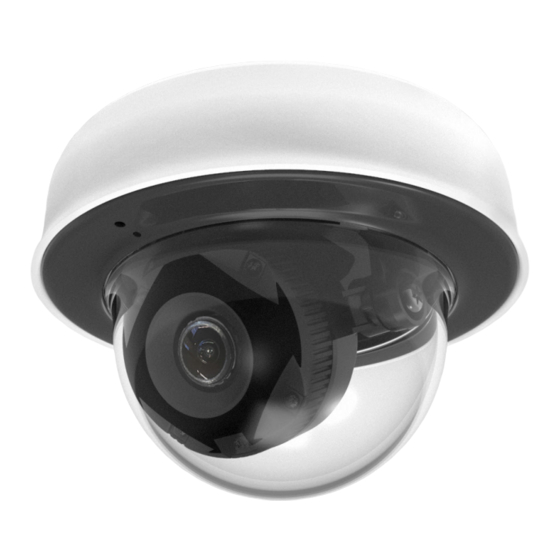
MV12 Installation Guide
Overview
The Cisco Meraki MV12 is a networked camera that is exceptionally simple to deploy and configure due to its integration
into the Meraki dashboard and the use of cloud augmented edge storage. The MV family eliminates the complex and
costly servers and video recorders required by traditional solutions which removes the limitations typically placed on
video surveillance deployments.
Package Contents
In addition to the MV camera, the following are provided:
• Phillips head wall mounting screws
• Wall screw anchors for masonry (brick, concrete)
• Torx key
• Wall mount plate
Ethernet Port
The MV12 features a 1000BASE-T Ethernet port that supports 802.3af Power-over-Ethernet (PoE).
Pre-Install Preparation
You should complete the following steps before going on-site to perform an installation.
Configure Your Network in Dashboard
The following is a brief overview only of the steps required to add an MV12 to your network. For detailed instructions
about creating, configuring and managing Meraki Camera networks, refer to the online documentation
(https://documentation.meraki.com/MV).
1
Advertisement

Related Manuals for Cisco Meraki MV12


Summary of Contents for Cisco Meraki MV12
-
Page 1: Package Contents
Overview The Cisco Meraki MV12 is a networked camera that is exceptionally simple to deploy and configure due to its integration into the Meraki dashboard and the use of cloud augmented edge storage. The MV family eliminates the complex and costly servers and video recorders required by traditional solutions which removes the limitations typically placed on video surveillance deployments. -
Page 2: Dns Configuration
1. Login to http://dashboard.meraki.com. If this is your first time, create a new account. 2. Find the network to which you plan to add your cameras or create a new network. 3. Add your cameras to your network. You will need your Meraki order number (found on your invoice) or the serial number of each camera, which looks like Qxxx-xxxx-xxxx, and is found on the bottom of the unit. - Page 3 2. Use template to determine mounting hole locations before screwing in the mount plate. Peel backing from mount template to stick on wall. Screw the mounting plate onto the wall in pre-determined locations. Use template holes to align the mounting plate. Connect PoE cable to camera.
- Page 4 5. Align camera to mounting plate studs. Slide camera onto studs and turn camera clockwise to secure camera to plate. If cable run is not coming from directly behind the camera, the cable guard will need to be removed. Below are two mounting examples.
- Page 5 6. Further secure camera to mounting plate by tightening the green security screw. 7. Aim the lens. Inspect the camera feed on the Meraki Dashboard to fine tune the picture. The camera sensor and lens unit can be physically tilted through a range of 65 degrees, rotated through a range of 350 degrees, and panned through a range of 350 degrees.
- Page 6 8. Replace the plastic dome. Turn dome clockwise to lock. 9. Remove protective cap from camera bubble.
-
Page 7: Wlan Capability
Powering the MV12 Remove the cable guard and route the Ethernet cable from an active port on a 802.3af PoE switch or PoE injector. Note: PoE supports a maximum cable length of 300 ft (100 m). WLAN Capability MV12 cameras running MV firmware 3.16 and newer can be configured as wireless clients. To learn how to configure MV12 wireless settings, check out our MV Wireless Configuration Guide.