
Related Manuals for GE AKTA ready XL


Summary of Contents for GE AKTA ready XL
- Page 1 185018004599 ÄKTA™ ready XL Operating Instructions Original instructions gelifesciences.com TeDIS Valid on Date Printed Printed on: 15-09-2023 11:27:35 ***...
-
Page 2: Table Of Contents
Table of Contents Table of Contents Introduction ......................4 About this manual ............................. 5 Important user information ........................6 Associated documentation ........................9 Abbreviations .............................. 11 Safety instructions ....................12 Safety precautions ............................ 13 Labels ................................21 Emergency procedures ........................... 24 System description .................... - Page 3 Table of Contents Controlled shutdown and removal of flow kit ................. 139 Maintenance ......................143 Troubleshooting ...................... 146 Reference information ................... 149 Specifications .............................. 150 Flow kit ordering information ........................ 152 Chemical resistance ..........................153 Recycling information ..........................156 Regulatory information ........................... 157 9.5.1 Contact information ...........................
-
Page 4: Introduction
1 Introduction Introduction About this chapter This chapter contains important user information, descriptions of safety notices, reg- ulatory information, intended use of ÄKTA ready XL, and lists of associated docu- mentation. In this chapter Section See page About this manual Important user information Associated documentation Abbreviations... -
Page 5: 1.1 About This Manual
1 Introduction 1.1 About this manual About this manual Purpose of this manual The Operating Instructions provide you with the information needed to install, oper- ate, and maintain the product in a safe way. Scope of this manual This manual is specific for ÄKTA ready XL and describes the safety instructions and procedures required to operate ÄKTA ready XL together with either the ¾... -
Page 6: Important User Information
1 Introduction 1.2 Important user information Important user information Read this before operating the product All users must read the entire Operating Instructions before installing, operat- ing or maintaining the product. Always keep the Operating Instructions at hand when operating the product. Do not operate the product in any other way than described in the user documenta- tion. - Page 7 1 Introduction 1.2 Important user information Prerequisites In order to operate ÄKTA ready XL in the way it is intended, the following prerequi- sites must be fulfilled: • The user must be acquainted with the use of general bioprocessing equipment and with handling of biological materials.
- Page 8 1 Introduction 1.2 Important user information Notes and tips Note: A note is used to indicate information that is important for trouble-free and optimal use of the product. Tip: A tip contains useful information that can improve or optimize your proce- dures.
-
Page 9: Associated Documentation
Bill of Material Description of process-related compo- nents. Spare Part List List of spare parts available from GE Healthcare. Third-party component documentation Documentation for components produced by a third-party are, if existent, also inclu- ded in the document package. - Page 10 1 Introduction 1.3 Associated documentation Related literature This list describes related literature that may be useful. Contact your GE Healthcare representative for more details. Document Product Product code ÄKTA ready XL chromatography system Data file KA1755181217DF ReadyToProcess columns User Manual...
-
Page 11: Abbreviations
1 Introduction 1.4 Abbreviations Abbreviations Introduction This section explains abbreviations that appear in the user documentation for ÄKTA ready XL. Terminology Term Definition Control unit Phosphate-buffered saline PTFE Polytetrafluoroethylene Hygienic tubing connection Uninterruptible power supply Pneumatically actuated valve (automatic valve) ÄKTA ready XL Operating Instructions 29281616 AE TeDIS Valid on Date Printed Printed on: 15-09-2023 11:27:35 ***... -
Page 12: Safety Instructions
2 Safety instructions Safety instructions About this chapter This chapter describes safety precautions, labels and symbols that are attached to the equipment. In addition, the chapter describes emergency and recovery proce- dures, and provides recycling information. In this chapter Section See page Safety precautions Labels... -
Page 13: Safety Precautions
2 Safety instructions 2.1 Safety precautions Safety precautions Introduction ÄKTA ready XL is powered by mains voltage and handles materials that may be haz- ardous. Before installing, operating or maintaining the system, you must be aware of the hazards described in this manual. The safety precautions in this section are grouped into the following categories: •... -
Page 14: Flammable Liquids And Explosive Environment
2 Safety instructions 2.1 Safety precautions WARNING Do not operate the product in any other way than described in the user documentation. WARNING Do not use the product if it is not working properly, or if it has suf- fered any damage, for example: •... -
Page 15: Personal Protection
Installing and moving WARNING The product must be installed and prepared by GE Healthcare personnel or a third party authorized by GE Healthcare. WARNING Move transport crates. Make sure that the lifting equipment has the capacity to safely lift the crate weight. - Page 16 2 Safety instructions 2.1 Safety precautions CAUTION Heavy object. Because of the significant weight of the product, great care must be taken not to cause squeezing or crushing inju- ries during movement. • At least three people are needed when rolling the system out of the transport crate.
- Page 17 2 Safety instructions 2.1 Safety precautions Power supply WARNING Protective ground. The product must always be connected to a grounded power outlet. WARNING Access to power switch and power cord with plug. Do not block access to the power switch and power cord. The power switch must always be easy to access.
-
Page 18: Operation
2 Safety instructions 2.1 Safety precautions Operation WARNING Cap unused connections before operation. Make sure that all connections not in use are capped or directed to waste to avoid accidental hazardous leakage during operation. WARNING Never exceed the operating limits stated in this document and on the system label. - Page 19 2 Safety instructions 2.1 Safety precautions WARNING Use columns that withstand expected pressures. Otherwise the columns might rupture, resulting in injury. Use external safety pressure relief devices to protect the column, such as burst or rupture discs. WARNING The filter design pressure shall be same or higher than the flow kit design pressure.
- Page 20 WARNING Use only approved parts. Only spare parts and accessories that are approved or supplied by GE Healthcare may be used for main- taining or servicing the product. ÄKTA ready XL Operating Instructions 29281616 AE TeDIS Valid on Date Printed...
-
Page 21: Labels
2 Safety instructions 2.2 Labels Labels Introduction This section describes the various labels on ÄKTA ready XL and their meaning. System nameplate The system nameplate is located on the electrical cabinet. The texts and symbols that can be found on the system nameplate are explained in the table below. - Page 22 2 Safety instructions 2.2 Labels Label text Description Type of enclosure The enclosure type. Field wiring diagram Electrical schematics. This symbol indicates that electrical and electronic equipment must not be disposed of as unsorted municipal waste and must be collected separately. Please contact an authorized representative of the manufacturer for information concerning the de- commissioning of equipment.
- Page 23 IMPORTANT! Before service/maintenance or return to GE Healthcare, clean the equipment and accom- pany it with a decontamination statement, specifying substances with which it has been in contact during use and the method of cleaning.
-
Page 24: Emergency Procedures
2 Safety instructions 2.3 Emergency procedures Emergency procedures Introduction Under normal circumstances, ÄKTA ready XL should always be shut down as descri- bed in Section 6.3 Controlled shutdown and removal of flow kit, on page 139. Shutting down ÄKTA ready XL by pressing the EMERGENCY STOP button should only be performed if an emergency situation prevents normal shutdown. - Page 25 2 Safety instructions 2.3 Emergency procedures WARNING Emergency stop. Pressing the EMERGENCY STOP will not shut off mains power to the electrical cabinet. Pressing the EMERGENCY STOP button (B) will result in the following: • Pump motors stop immediately. • The built-in computer and other components will remain powered.
- Page 26 2 Safety instructions 2.3 Emergency procedures NOTICE Do not shut down ÄKTA ready XL by turning the Power switch (A), disconnecting the power cord or switching off the fixed power supply isolation switch. If shutdown is performed in such a way: •...
- Page 27 Reset the EMERGENCY STOP button by turning it clockwise. Restart the control software. NOTICE If ÄKTA ready XL fails to restart correctly following an emergency shutdown or power failure, contact GE Healthcare for further ad- vice and assistance. Power failure WARNING Power failure.
- Page 28 2 Safety instructions 2.3 Emergency procedures When power is lost, the onboard computer will continue to run for one more minute before it is automatically shut down in a controlled manner. However, the interface control unit of the control software, CU-960, located inside the electrical cabinet, is immediately shut down and the system is stopped.
- Page 29 2.3 Emergency procedures NOTICE If ÄKTA ready XL fails to restart correctly following an emergency shutdown or power failure, contact GE Healthcare for further ad- vice and assistance. ÄKTA ready XL Operating Instructions 29281616 AE TeDIS Valid on Date Printed...
-
Page 30: System Description
3 System description System description About this chapter This chapter provides an overview of the technical properties of ÄKTA ready XL sys- tem. The flow kits, that can be used with the system, are described in Section 3.5 Flow kits, on page In this chapter Section... -
Page 31: Overview
3 System description 3.1 Overview Overview Introduction This section describes the system and where further information may be found. The separate documents referred to are part of the documentation package provided in the delivery. ÄKTA ready XL is intended to be operated as an isocratic or gradient, low pressure, automated liquid chromatography system using ¾... - Page 32 3 System description 3.1 Overview If UNICORN is used as the control software, an operator console with integrated touchscreen and a keyboard is fitted to the system frame. Also, a computer and a control unit are installed in the electrical cabinet. Refer to the Bill of Material for more information on the computer and components in the electrical cabinet.
-
Page 33: Illustrations
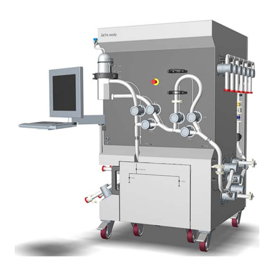
3 System description 3.2 Illustrations Illustrations ÄKTA ready XL with fitted flow kit and gradient section Note: Components of the flow kit and gradient section are described in Section 3.5 Flow kits, on page Part Function ÄKTA ready XL system ÄKTA ready XL flow kit and gradient section (ordered separately). - Page 34 3 System description 3.2 Illustrations Components on system — inlet side The illustration below shows the location of components on the inlet side of ÄKTA ready XL. The system is shown without the flow kit. Part Component ID tag Function Air trap vent XV-023 A valve controlling the level in air trap.
- Page 35 3 System description 3.2 Illustrations Part Component ID tag Function Installation The switch is used for releasing and engag- switch ing valves during flow kit and column instal- lation. The switch has three different posi- tions: Flow kit install: : This mode opens all valves.
- Page 36 3 System description 3.2 Illustrations Components on system — front The illustration below shows the location of components on the front of the system. The system is shown without the flow kits. Part Component ID tag Function Level sen- LEL-166 The level sensors LEL-166 and LEH-167 sors, fitting are used to measure the liquid level in the...
- Page 37 3 System description 3.2 Illustrations Part Component ID tag Function EMERGEN- The button stops the pump and places the CY STOP system in pause mode. button Air trap XV-021 , Three-valve assembly for air trap bypass/ valves XV-022, inline. XV-024 Cable con- Cable connectors and cables (not illustra- nectors and...
- Page 38 3 System description 3.2 Illustrations Components on system — outlet side The illustration below shows the location of components on the outlet side of the system. The system is shown without flow kit. Part Component ID tag Function Cable for AE-152 A cable connection to air sensor AE-152 connection...
- Page 39 3 System description 3.2 Illustrations Part Component ID tag Function Cable for CE-102/ A cable for connection to conductivity and connection TE-102 temperature sensor CE-102/TE-102 that is to conductiv- prefitted on the flow kit. ity and tem- perature sen- Cable for AE-121/ A cable for connection to pH meter connection...
- Page 40 3 System description 3.2 Illustrations Components on system — back The illustration below shows the location of components on the back of the system. The system is shown without flow kit. Part Function Inlet for lower cooling units Outlet for upper cooling unit System electrical cabinet door ÄKTA ready XL Operating Instructions 29281616 AE TeDIS Valid on Date Printed...
- Page 41 3 System description 3.2 Illustrations Components on system — pump wagon The illustration below shows the location of components on the ÄKTA ready XL pump wagon. The system is shown without flow kit. Part Function Pump head drive unit (2 pcs) Pressure plate for pump head (2 pcs) Pump wagon handle bar Pump wagon lock...
- Page 42 3 System description 3.2 Illustrations Location of connectors Connectors for the system power, compressed air, customer I/O, PROFIBUS™, and computer network are located on the inlet left-hand side of the system. The commu- nication cables for the operator console (only applicable for system with UNICORN) are located on the front of the system.
-
Page 43: Flowchart
3 System description 3.3 Flowchart Flowchart Diagram The flow path of ÄKTA ready XL is illustrated below. • Blue color illustrates system components. • Green color illustrates isocratic flow kit components and tubing (wetted compo- nents). • Orange color illustrates gradient section components and tubing (wetted com- ponents). - Page 44 3 System description 3.3 Flowchart AE-151 P-201.A P-201.B CE-101/TE-101 PE-111 XV-021 XV-024 XV-025 XV-027 PE-112 AE-152 PE-113 FE-141 CE-102/TE-102 AE-121/TE-121 AE-131 ÄKTA ready XL Operating Instructions 29281616 AE TeDIS Valid on Date Printed Printed on: 15-09-2023 11:27:35 ***...
- Page 45 3 System description 3.3 Flowchart Process component and meters The table below describes the system components and flow kit components shown in the flowchart. Part Function AE-121/TE-121 pH/temperature sensor AE-131 UV cell AE-151 and AE-152 Air sensors AT-221 Air trap BA1 to BA6 Buffer A inlets BB1 to BB4...
- Page 46 3 System description 3.3 Flowchart Part Function XV-027 Filter outlet valve XV-031 Column top inlet valve XV-032 Column top outlet valve XV-033 Column bottom inlet valve XV-034 Column bottom outlet valve XV-035 Column bypass valve XV-051 to XV-056 Outlet valves ÄKTA ready XL Operating Instructions 29281616 AE TeDIS Valid on Date Printed Printed on: 15-09-2023 11:27:35 ***...
-
Page 47: System Components
3 System description 3.4 System components System components In this section Section See page 3.4.1 Skid and electrical cabinet 3.4.2 Control system components 3.4.3 System pumps 3.4.4 Valves 3.4.5 Transmitters and sensors Introduction This section provides descriptions of ÄKTA ready XL and an overview of all compo- nents, including the control system. -
Page 48: Skid And Electrical Cabinet
3 System description 3.4 System components 3.4.1 Skid and electrical cabinet 3.4.1 Skid and electrical cabinet Skid and cabinet The system is designed for use in a production environment. The system occupies a compact space that makes it easy to fit into any location in the production facility. The stainless steel design supports process components and the electrical cabinet in one unit. -
Page 49: Control System Components
Software Description control UNICORN Control software developed by GE Healthcare and owned by GE. The control software is part of the configuration. DeltaV Control software developed and owned by Emerson Process Management group of companies. The control software can be part of the configuration and configured by GE Healthcare. - Page 50 3 System description 3.4 System components 3.4.2 Control system components NOTICE Forcing the control software or the Microsoft Windows operating system to close during upload of data from the control unit will cause the unsaved data to be lost. Computer (only applicable to systems with UNICORN) The computer is built into the electrical cabinet and fully protected from the outside environment.
-
Page 51: System Pumps
3 System description 3.4 System components 3.4.3 System pumps 3.4.3 System pumps Introduction This section describes the pumps of ÄKTA ready XL. Description ÄKTA ready XL is equipped with two identical pumps with disposable pump cham- bers (heads). • P-201.A allows for isocratic operation. •... - Page 52 3 System description 3.4 System components 3.4.3 System pumps Note: Avoid locking the pump wagon wheels when the wagon is pinlocked under the system if the system is intended to be moved. A pump needs an open flow path, and the switch set to Run, to receive a start signal. For instructions on how to fit the pump chamber to the motor see Section 5.2 Install disposable flow kits, on page...
- Page 53 3 System description 3.4 System components 3.4.3 System pumps Safety monitor indicator and alarm reset A button with blue indicator light, labeled Reset, is located on the system's inlet side. The light indicates the status for safety monitoring. After an alarm, the button is used to reset safety monitoring.
- Page 54 3 System description 3.4 System components 3.4.3 System pumps Note: The Reset button must also be pressed after using the installation switch. ÄKTA ready XL Operating Instructions 29281616 AE TeDIS Valid on Date Printed Printed on: 15-09-2023 11:27:35 ***...
-
Page 55: Valves
3 System description 3.4 System components 3.4.4 Valves 3.4.4 Valves Introduction This section describes the valves and provides valve macros for the air trap, filter and column. Refer to the Software Design Specification for more information on valve macros. Description There are 28 pinch valves in total, of which 27 are large pinch valves and one is a small pinch valve. - Page 56 3 System description 3.4 System components 3.4.4 Valves Step Action Put the pin in to the unlocked position to enable the valve to be opened or closed. Note: The valves are fitted to minimize the length of the tubing. Therefore the di- rection of the pin to lock or unlock varies due to how the valves are fitted on the system.
- Page 57 3 System description 3.4 System components 3.4.4 Valves Step Action Slide the valve finger guard to open the valve tubing compartment ÄKTA ready XL Operating Instructions 29281616 AE TeDIS Valid on Date Printed Printed on: 15-09-2023 11:27:35 ***...
- Page 58 3 System description 3.4 System components 3.4.4 Valves Overview Valves Description Default posi- tion XV-001 to Inlet A valves, located on the left-hand side Closed XV-006 of the system. XV-011 to Inlet B valves, located on the left-hand side Closed XV-014 of the system XV-021 to...
- Page 59 3 System description 3.4 System components 3.4.4 Valves Filter valves The filter valve blocks are directly connected to the air trap valve blocks and to tubing going to the air sensor prior to the column. If no customer filter is used, set the valves to bypass.
-
Page 60: Transmitters And Sensors
3 System description 3.4 System components 3.4.5 Transmitters and sensors 3.4.5 Transmitters and sensors Introduction With the exception of the air trap level sensors, all sensors are disposable and deliv- ered separately as part of the flow kit. The transmitters and level sensors that are de- livered with the system are briefly described in this section. - Page 61 3 System description 3.4 System components 3.4.5 Transmitters and sensors The level sensors can be fitted to the disposable air trap (part of the flow kit) for auto- matic liquid level control and liquid detection. The sensor assembly consists of a low level sensor, LEL-166 (A), and a high level sen- sor, LEH-167 (B).
-
Page 62: Flow Kits
3 System description 3.5 Flow kits Flow kits In this section Section See page 3.5.1 Flow kit description 3.5.2 Flow kit parts and components 3.5.3 Gradient section and components Introduction This chapter provides descriptions of the disposable flow kits and an overview of the components. -
Page 63: Flow Kit Description
Flow kit description Introduction NOTICE Only use flow kits supplied by GE Healthcare. ÄKTA ready XL is used with specific flow kits that include all the necessary tubing, from inlet to outlet, including flow cell, air trap, column connection tubing, and pump heads. - Page 64 3 System description 3.5 Flow kits 3.5.1 Flow kit description Flow kit durability The total time for usage for each disposable flow kit is a total of 48 hours. The 48 hours are limited to a period of 14 days from the initial wetting of the flow kit. After 48 hours of usage or 14 days after initial wetting of the flow kit, the kit must be discar- ded.
-
Page 65: Flow Kit Parts And Components
3 System description 3.5 Flow kits 3.5.2 Flow kit parts and components 3.5.2 Flow kit parts and components Introduction This section describes the isocratic flow kit. Flow kit parts The flow kit is delivered in five separate parts. Part Function Inlet manifold Tubing with 6 connectors for inlets and one outlet for connecting to the pump head, including air... - Page 66 3 System description 3.5 Flow kits 3.5.2 Flow kit parts and components Part Function Column connec- Tubing with one connector for the air trap tubing tion tubing and one outlet connecting to the outlet manifold. The column connection part also has two connec- tors for a column.
- Page 67 3 System description 3.5 Flow kits 3.5.2 Flow kit parts and components Part Component Function Air sensor AE-151 A sensor detecting air in the line. The sensor can be fitted to any inlet. Inlet mani- XV-001 to Manifold with 6 inlets corresponding to fold XV-006 valves XV-001 to XV-06.
- Page 68 3 System description 3.5 Flow kits 3.5.2 Flow kit parts and components Part Component Function Pressure PE-112 Flow cell for pressure sensor PE-112. sensor The sensor measures the pressure be- tween the air trap or filter and the col- umn, and is part of the high pressure safety monitoring.
- Page 69 3 System description 3.5 Flow kits 3.5.2 Flow kit parts and components Part Component Function Flow meter FE-141 Flow cell for flow meter sensor FE-141. cell Pressure PE-113 Flow cell for safety pressure sensor sensor PE-113, measures pressure between the column and the outlet manifold, and is part of the high pressure safety monitoring.
- Page 70 3 System description 3.5 Flow kits 3.5.2 Flow kit parts and components Part Component Function Conductivity CE-101/ Sensor measuring the conductivity and and temper- TE-101 temperature of the liquid. ature sensor Reducer Tubing size adapter. Only used in iso- cratic mode. Sanitization All parts of the flow kit are delivered double bagged and sanitized through gamma ir- radiation.
-
Page 71: Gradient Section And Components
3 System description 3.5 Flow kits 3.5.3 Gradient section and components 3.5.3 Gradient section and components Introduction This section describes the gradient section. Gradient section parts The gradient section is delivered as three parts. Each part constituting the gradient section are sanitized by gamma irradiation and ready for use with ÄKTA ready XL. Detailed specifications for the section are found in the product documentation sup- plied with each section. -
Page 72: Process Control Software
Prerequisite knowledge A working knowledge of the control software is required to operate ÄKTA ready XL in a safe manner. Contact your local GE Healthcare or your control software representative for advice if required. System networks ÄKTA ready XL can be controlled from a stand-alone computer or remotely from a network. - Page 73 3 System description 3.6 Process control software Software modules Provided your system is delivered with UNICORN, the UNICORN control software consists of four modules: Module Function Administration File handling and administration tasks; for example, definition of systems and managing user profiles. Method Editor Method creation and editing for preprogram- med control of the system.
- Page 74 3 System description 3.6 Process control software Workflow The workflow for using UNICORN software for automatic control includes the follow- ing general steps: Step Action Program a method run using the UNICORN software. It is possible to use an existing method or modify an existing method to meet your run objec- tives.
- Page 75 3 System description 3.6 Process control software Alarms Signals If any equipment is connected that has lower limits than the system, the alarm levels must be set accordingly. If an analog or digital signal passes the predetermined alarm level, several things happen at once: •...
-
Page 76: Installation
4 Installation Installation About this chapter This chapter describes how to transport, move and setup ÄKTA ready XL. The system is designed for ease-of-use and is easy to install and set up. Components are either fitted on the system or provided as part of the flow kit. In this chapter Section See page... -
Page 77: Site Requirements
4 Installation 4.1 Site requirements Site requirements System dimensions Property Value Width × Depth × Height (approximate 1295 × 1215 × 1920 mm ±10 mm) System dry weight (approximate) 715 kg Space requirements Make sure to have enough free space on the sides and in front of the system when it has been installed to allow for service and maintenance. -
Page 78: Transport And Moving Of The System
4 Installation 4.2 Transport and moving of the system Transport and moving of the system Introduction This section outlines important information that must be considered when trans- porting ÄKTA ready XL. For detailed information regarding transporting the transport crate and the removal of the system from the crate, refer to ÄKTA ready XL Unpacking Instructions, 29302613. - Page 79 4 Installation 4.2 Transport and moving of the system • Knife NOTICE Do not use a forklift to remove the system from the crate. The sys- tem must be rolled out using the enclosed ramp. Step Action Remove the bolts marked with black circles supporting the short ends of the crate.
- Page 80 4 Installation 4.2 Transport and moving of the system Step Action Tighten the bolts to raise the lower crossbeam at the back of the system. Remove the bottom leverage blocks. Tip: You may need to use a hammer to remove the leverage blocks. Remove the lower crossbeam and the support blocks under the system.
- Page 81 Examine the equipment for any apparent damage. If damage is found, document this carefully. If any equipment is missing or damage is found, contact your GE Healthcare repre- sentative immediately. Move the system on level surfaces ÄKTA ready XL can be rolled on hard and level surface with brakes on wheels on the system and the pump wagon released.
- Page 82 4 Installation 4.2 Transport and moving of the system Moving ÄKTA ready XL over uneven surfaces requires the use of a forklift. Before lift- ing the system the pump wagon must be disconnected. Follow the instructions below to disconnect the pump wagon from the system and move the wagon and system using a forklift.
- Page 83 4 Installation 4.2 Transport and moving of the system Step Action Unscrew the eight screws on the pump motor cover. Note: Repeat this step for the second pump. Disconnect the two cables on the pump motor. The connections can be turned for easier access.
- Page 84 4 Installation 4.2 Transport and moving of the system Step Action Remove the bolts and fitting for the grounding wire and the cable holders so that the cables and holders can be placed on the system. Pull the disconnected pump wagon away from the system. Position buffering blocks on the lifting forks.
- Page 85 4 Installation 4.2 Transport and moving of the system Move the system Step Action Make sure the pump wagon is disconnected from the system. Position buffering blocks on the lifting forks. Carefully position the lifting forks so that they are positioned under the system.
-
Page 86: Setup
4 Installation 4.3 Setup Setup Introduction This section describes the steps that need to be taken to set up ÄKTA ready XL be- fore use. In this section Section See page 4.3.1 Assembly 4.3.2 Setup of control system and network 4.3.3 Connect compressed air supply 4.3.4 Guidelines for connections ÄKTA ready XL Operating Instructions 29281616 AE... -
Page 87: Assembly
4 Installation 4.3 Setup 4.3.1 Assembly 4.3.1 Assembly Introduction ÄKTA ready XL is delivered fully assembled apart from the operator console. This section describes how to assemble the operator console and how to lock the wheels. Lock the wheels After positioning the system at its designated location, lock the wheels (illustrated below). - Page 88 4 Installation 4.3 Setup 4.3.1 Assembly NOTICE Operator console • Do not use the operator console to push or drag the system • Do not lean on the console The console arm is only designed to support the weight of the op- erator console.
- Page 89 4 Installation 4.3 Setup 4.3.1 Assembly Step Action Carefully slide the console arm over the system console rod (B) until it is firmly attached. Keep the foam protection (A) in place when attaching the console arm. Remove the foam protection. Fit the two cables to the connectors on the back of the console.
-
Page 90: Setup Of Control System And Network
A customer I/O connection is located on the communications panel on the side of the electrical cabinet. There are many different applications for customer I/O connec- tions. Contact your local GE Healthcare representative for more detailed technical infor- mation. ÄKTA ready XL Operating Instructions 29281616 AE... -
Page 91: Connect Compressed Air Supply
4 Installation 4.3 Setup 4.3.3 Connect compressed air supply 4.3.3 Connect compressed air supply Introduction This section describes how to connect the compressed air supply. For requirements on air supply, refer to Section 4.1 Site requirements, on page 77 Section 9.1 Specifications, on page 150. -
Page 92: Guidelines For Connections
4 Installation 4.3 Setup 4.3.4 Guidelines for connections 4.3.4 Guidelines for connections Introduction This section provides guidelines for the connection of process components to ÄKTA ready XL. Process connections • Use non-collapsible piping or tubing that has an internal diameter sufficient for the flow rate specified. -
Page 93: Power Supply
Power supply Power supply connection The mains power supply must be connected and configured by authorized service personnel. Contact your GE Healthcare representative to arrange assistance if re- quired. Use the supplied network cables for connection to network as appropriate. -
Page 94: Preparation
Flammable liquids and explosive environment, on page 14 • Personal protection, on page 15 • Operation, on page 18 NOTICE Only use flow kits supplied by GE Healthcare. ÄKTA ready XL Operating Instructions 29281616 AE TeDIS Valid on Date Printed Printed on: 15-09-2023 11:27:35 ***... - Page 95 5 Preparation NOTICE Always perform a flow kit installation test when installing a flow kit. The test includes verification of the sensors. NOTICE Disconnect power. To prevent equipment damage, always dis- connect the power from the product before an instrument mod- ule is removed or installed, or a cable is connected or disconnec- ted.
-
Page 96: Start The System And Log On To Control Software
5 Preparation 5.1 Start the system and log on to control software Start the system and log on to control software Introduction ÄKTA ready XL is normally left switched on between runs. Switch off the system only during monthly maintenance and repair, or when not in operation for a longer period of time (more than a few days). -
Page 97: Install Disposable Flow Kits
5 Preparation 5.2 Install disposable flow kits Install disposable flow kits Introduction This section describes how to install the flow kit and the gradient section. The installation is divided into several procedures that are recommended to be per- formed in the following sequence: Prepare the system for flow kit installation. - Page 98 5 Preparation 5.2 Install disposable flow kits The flow kit serial number is found on the label of the transport box. Prepare the system for flow kit installation Step Action Unlock all large pinch valves on the system by setting each locking pin to the unlocked position.
- Page 99 5 Preparation 5.2 Install disposable flow kits Step Action Lock all large pinch valves on the system by setting each locking pin to the locked position. Note: Locking the pinch valves is done to prevent the valves from actuating and closing while installation is occurring.
- Page 100 5 Preparation 5.2 Install disposable flow kits Step Action Open the door in front of the pump wagon (A). Then release the pump wag- on from the system, pull out and turn the two locking pins clockwise (B) on either side of the pump wagon frame. Pull out the pump wagon from under the system without pulling the cables (C).
- Page 101 5 Preparation 5.2 Install disposable flow kits Step Action Remove the screw cap that covers the clamp ring screw (D) using the tool illustrated. Take the 8 mm HEX attachment head and fit it to the tool as illustrated be- low.
- Page 102 5 Preparation 5.2 Install disposable flow kits Step Action Fit the pump chamber to the pump motor and the pressure plate to the pump head. Make sure the pump head is oriented so that the clamp ring screw (F) loca- ted at the back is aligned with the hole for the screw cap.
- Page 103 5 Preparation 5.2 Install disposable flow kits Step Action Change the attachment head of the torque tool to tighten the clamp ring screw (F) at the back of the pump chamber to a torque of 5 Nm with the torque tool. Tip: It is recommended to fit the 5 mm attachment head onto the clamp ring screw first, then attach the torque tool to the attachment head due to limi-...
- Page 104 5 Preparation 5.2 Install disposable flow kits Position the isocratic inlet manifold Step Action Locate and open the bag with the isocratic inlet manifold. Hang the isocratic inlet manifold so it is supported by the inlet A valves (XV-001 to XV-006) (A). Then connect the isocratic inlet manifold to the isocratic pump chamber inlet labeled IN using a TC clamp (B).
- Page 105 5 Preparation 5.2 Install disposable flow kits Step Action Hang the gradient inlet manifold so that it is supported by the inlet valves but shifted back against the system. Position and connect the gradient inlet manifold to the gradient pump chamber inlet labeled IN with a TC clamp as illustrated below.
- Page 106 5 Preparation 5.2 Install disposable flow kits Step Action Locate the jumper tubing in the gradient section. Connect the two pump head outlets, labeled OUT, with the pump jumper tubing using TC clamps. Note: The T-connection on the pump jumper tubing must be positioned closest to the gradient pump.
- Page 107 5 Preparation 5.2 Install disposable flow kits Position the air trap tubing Step Action Locate the air trap tubing that contains the air trap, tubing size adapter, and the sensors CE-101/TE-101, PE-111, PE-112, and AE-152. Hold the air trap at its base with your left hand and the filter tubing loop with your right hand, then push in the air trap in its snap holder.
- Page 108 5 Preparation 5.2 Install disposable flow kits Step Action Hang the air trap tubing on the valves on the front of the system as illustra- ted below. Then position the tubing so that it is located on the opening side of each valve.
- Page 109 5 Preparation 5.2 Install disposable flow kits Step Action For the isocratic setup, connect the air trap tubing (A) to the pump cham- ber outlet labeled OUT with a TC clamp with the tubing size adapter (B). The illustration above shows the isocratic setup. For the gradient setup, connect the air trap tubing to the jumper tubing without using the tubing size adapter.
- Page 110 5 Preparation 5.2 Install disposable flow kits Step Action Connect the CE-101/TE-101 sensor to the the cable connector located on the air trap flow kit leading to the pump chamber. Secure the connection by twisting the locking ring clockwise on the cable connector.
- Page 111 5 Preparation 5.2 Install disposable flow kits Install the inlet manifolds and air trap tubing Note: Open the pinch valve, insert tubing and close the valve by performing the following actions: 1. Position the tubing and open the valve safety cover. 2.
- Page 112 5 Preparation 5.2 Install disposable flow kits Step Action If your process requires a gradient setup, insert the tubing of the gradient inlet manifold into the inlet valves, then close the valves. Tip: Position the tubing as close to the system frame as possible, then open the valve safety cover and let the inlet tubing rest on the covers before starting to inserting the tubing.
- Page 113 5 Preparation 5.2 Install disposable flow kits Step Action Insert the air trap tubing into the valves, then close the valves. Position and install the column tubing Step Action Locate the column tubing of the flow kit. ÄKTA ready XL Operating Instructions 29281616 AE TeDIS Valid on Date Printed Printed on: 15-09-2023 11:27:35 ***...
- Page 114 5 Preparation 5.2 Install disposable flow kits Step Action Hang the column tubing on the valves so it is supported by the column valves located on the right side of the system. Insert the tubing in the column valves starting from the top and close the valves.
- Page 115 5 Preparation 5.2 Install disposable flow kits Position and install the outlet manifold Step Action Locate the outlet manifold. Position the outlet manifold on the corresponding outlet valves on the right side of the system. Open the valves and insert the tubing into the valves, then close the valves. ÄKTA ready XL Operating Instructions 29281616 AE TeDIS Valid on Date Printed Printed on: 15-09-2023 11:27:35 ***...
- Page 116 5 Preparation 5.2 Install disposable flow kits Step Action Connect the outlet manifold to the column tubing with a TC clamp. Make sure that the fastening handles of the TC clamps are facing out- wards. ÄKTA ready XL Operating Instructions 29281616 AE TeDIS Valid on Date Printed Printed on: 15-09-2023 11:27:35 ***...
- Page 117 5 Preparation 5.2 Install disposable flow kits Step Action Insert and fasten the rigid Krohne™ tube on the outlet tubing into the flow meter FE-141 located in the indention on the right side of the system. a. Open the tube holder (A). b.
- Page 118 5 Preparation 5.2 Install disposable flow kits Step Action Make sure to position the outlet manifold tubing on the left side of the hook. Install system components to the flow kit Step Action Locate the level sensor fixture (with level sensors LEL-166 and LEL-167), the lever, and the strap on the system.
- Page 119 5 Preparation 5.2 Install disposable flow kits Step Action Fit the reusable level sensor fixture to the air trap using the strap (A). Tighten the fixture to the air trap using the lever (B). The base of the level sensor should be positioned flush to the air trap rim. Fit the air trap vent tubing into the air trap vent valve, XV-023, and close the valve lock.
- Page 120 5 Preparation 5.2 Install disposable flow kits Connect the sensors Step Action Connect the AE-151 air sensor to cables from the cable gland located on the inlet side of the system cabinet. Connect the three pressure cells (PE-111, PE-112, and PE-113) with ca- bles from their respective cable glands (A, B, and C) on the front and inlet (right) side of the system cabinet.
- Page 121 5 Preparation 5.2 Install disposable flow kits Step Action Connect the two optical fiber cables for UV sensor, AE-131 (D) NOTICE Do not overbend the optical fiber cables for the UV sen- sor. This can result in the optical fibers breaking. Connect the pH and temperature sensor, AE-121/TE-121 (E).
- Page 122 5 Preparation 5.2 Install disposable flow kits Step Action Unlock the pin locks on all large pinch valves. Turn the installation switch to the Run position. Then press the Reset but- ton. The flow kit is assembled and the system can be prepared for the relevant flow kit installation test, see Section 5.3 Perform flow kit installation test, on page...
-
Page 123: Perform Flow Kit Installation Test
5 Preparation 5.3 Perform flow kit installation test Perform flow kit installation test Introduction The flow kit must be tested to verify that sensors and meters are correctly installed before use. A flow kit installation test method is available for this purpose. A success- ful test provides an installation report that can be saved as a pdf or printed. - Page 124 5 Preparation 5.3 Perform flow kit installation test Prepare for the dry flow kit installation test Step Action Make sure the system is set up with a flow kit without any connections to liquid, and that the flow kit is completely dry. Make sure each flow kit serial number is noted.
- Page 125 5 Preparation 5.3 Perform flow kit installation test Stage Description Monitor the test on the screen. A message window displays the running steps. Scrolling will be needed to view all the results in the message window. To clear the message window of the currently displayed re- sults, click Confirm.
-
Page 126: Prime To Remove Air From The Pump And Flow Path
5 Preparation 5.4 Prime to remove air from the pump and flow path Prime to remove air from the pump and flow path Introduction This section describes the recommended procedure on how to remove air from the pump and flow path. The procedure is necessary to perform when a previously un- used inlet is connected, and/or when changing the tank to a previously used inlet. - Page 127 5 Preparation 5.4 Prime to remove air from the pump and flow path Priming procedure This instruction sets column and filter to bypass, and ramps up the pump adequately for priming. Note: The air trap is set to inline as default and can be used to visually detect air bubbles.
- Page 128 5 Preparation 5.4 Prime to remove air from the pump and flow path Step Action If your system is equipped with a second pump and the gradient setup, re- peat the the procedure from step one for the inlets on the B line. Tip: Inlet B4 is the inlet located furthest from the pump, Inlet B3 is the second furthest etc.
-
Page 129: Install Filter (Optional)
5 Preparation 5.5 Install filter (optional) Install filter (optional) Introduction The disposable flow kit is prepared to be fitted with a customer supplied filter. This section describes how to install the filter to the flow kit. Install filter Step Action Open the TC clamp by Filter position above pinch valve XV-025. -
Page 130: Operation
6 Operation Operation About this chapter This chapter provides the information required to start, run and shut down ÄKTA ready XL after a run. For instructions on method/phase creation and results evaluation, refer to the con- trol software user documentation. Note: Make sure the installation steps described in the previous chapter have been performed. -
Page 131: Connect A Column
6 Operation 6.1 Connect a column Connect a column Introduction This section outlines the steps needed to connect a column to ÄKTA ready XL using UNICORN control software. For other control software, refer to the provided documentation for instructions. Although ReadyToProcess columns are recommended for use with ÄKTA ready XL, other columns may be used provided they are capable of withstanding the maximum system pressure. - Page 132 6 Operation 6.1 Connect a column Preparations The alarm for the air sensor located before the column must be disabled before filling the system/column with liquid (Alarms →Air_Alarm →Disabled). Connect an empty column Follow the instruction below to connect an empty column to ÄKTA ready XL. Step Action Connect tubing between the system valve marked COLUMN BOTTOM...
- Page 133 6 Operation 6.1 Connect a column Connect a packed column with bypass lines/valves Follow the instruction below to connect a pre-packed column with bypass lines/ valves to ÄKTA ready XL. Step Action Connect tubing between the column bottom and the system valve marked COLUMN BOTTOM.
-
Page 134: Run A Method
6 Operation 6.2 Run a method Run a method Introduction Running a method or phase on ÄKTA ready XL can be a largely automatic procedure. User interaction can be mainly required in the preparation phase, which includes connecting the column and the required containers, checking that all connections are correctly assigned, and that flow kit type and volumes are correct. - Page 135 6 Operation 6.2 Run a method Step Action Select the method to start. Click OK. A Start Protocol is displayed, consisting of a number of dialog boxes. For example, on the Variables page, it is possible to fine-tune the method be- fore proceeding.
- Page 136 6 Operation 6.2 Run a method More information regarding the monitoring possibilities that the UNICORN user in- terface offers is available in the UNICORN User Manual. End - Normal completion If no unexpected events occur during the run, UNICORN enters END state at method completion without need for user interaction.
- Page 137 6 Operation 6.2 Run a method Step Action Double-click the result file. The result file opens in a Chromatogram panel. To change the layout of the Chromatogram panel, right-click and and then click Customize. Select which curves to display by clicking them in the Curves tab.
- Page 138 6 Operation 6.2 Run a method Step Action In the Print Chromatograms dialog box, select print format and layout options. Click Preview. In the Customise Report window, verify that the layout is correct. Click Exit to return to the Print Chromatograms dialog box. Click OK.
-
Page 139: Controlled Shutdown And Removal Of Flow Kit
6 Operation 6.3 Controlled shutdown and removal of flow kit Controlled shutdown and removal of flow kit Introduction This section provides instructions on how to remove the disposable flow kit and to shut down ÄKTA ready XL and the control software. Remove flow kit after the run (optional) There are several optional ways to remove the flow kit. - Page 140 6 Operation 6.3 Controlled shutdown and removal of flow kit Step Action Disconnect the flow kit sensors from the system. Make sure to fit caps to all sensor connections on the system with the caps provided on the system. Disconnect and remove customer tubing. Set the switch to Flowkit install to open the pinch valves, and press Re- set.
- Page 141 6 Operation 6.3 Controlled shutdown and removal of flow kit Step Action Carefully disconnect and lift off the air trap level sensor fixture, level sen- sors, lever, and the strap from the disposable air trap. These items are re- usable and must not be removed from the system NOTICE Do not remove the level sensor fixture, level sensors, lever, and the strap from the system.
- Page 142 6 Operation 6.3 Controlled shutdown and removal of flow kit Step Action Carefully disconnect and lift off the air trap level sensor fixture, level sen- sors, lever, and the strap from the disposable air trap. These items are re- usable and must not be removed from the system NOTICE Do not remove the level sensor fixture, level sensors, lever, and the strap from the system.
-
Page 143: Maintenance
ÄKTA ready XL. This chapter provides instructions for maintenance by the user. Preventive mainte- nance should be performed on a yearly basis by qualified service personnel author- ized by GE Healthcare. Contact your GE Healthcare representative for more service information. Precautions... - Page 144 It is important that the user is always attentive about the status and operation of the equipment. The cause of any abnormal behavior or aberrant noise should be exam- ined and removed. If the problem is non-trivial, contact your local GE Healthcare rep- resentative.
- Page 145 7 Maintenance Step Action Empty the air trap completely from liquid using the Drain instruction for the air trap (see Air trap valves, on page 58). Use the instruction System →Calibrate →LSL166_air to calibrate the low level sensor using air. Use the instruction System →Calibrate →LSH167_air to calibrate the high level sensor using air.
-
Page 146: Troubleshooting
ÄKTA ready XL. If the suggested actions in this guide do not solve the problem or if the problem is not covered by this guide, contact your GE Healthcare representative. Precautions... - Page 147 5 sec, restart sys- software. tem. If this action do not solve the problem, contact GE Healthcare Service for support. Communication failure • Make sure the system is switched on. Check net- during a run.
- Page 148 8 Troubleshooting Component Problem Corrective action Valves The alarm Valve error A valve lock may be open. Check the valve locks. (valve error) is dis- Note: played. Before attempting to close the manual valve lock, A valve lock may be make sure the valve is in an open position.
-
Page 149: Reference Information
9 Reference information Reference information About this chapter This chapter provides reference information that may become useful when installing, operating, maintaining and troubleshooting ÄKTA ready XL. In this chapter Section See page Specifications Flow kit ordering information Chemical resistance Recycling information Regulatory information Health and Safety Declaration Forms More information... -
Page 150: Specifications
9 Reference information 9.1 Specifications Specifications General specifications Refer to the system nameplate and the General specification document in the turn- over package for additional specification information. Property Value Dimensions (Width × Depth × Height) 1295 × 1215 × 1920 mm System dry weight (approximate) Maximum 715 kg Power supply... - Page 151 9 Reference information 9.1 Specifications Property Value Process temperature 5°C to 30°C (41 to 86°F) Liquid temperature 5°C to 30°C (41 to 86°F) Liquid density 0.8 to 1.2 kg/L Relative air humidity 20% to 95%, non-condensing. Ambient temperature 5°C to 30°C (41 to 86°F) Altitude 2000 m System capacity...
-
Page 152: Flow Kit Ordering Information
9 Reference information 9.2 Flow kit ordering information Flow kit ordering information Introduction This section contains ordering information for ÄKTA ready XL flow kits and gradient flow section. Flow kit options Product Code No. ÄKTA ready XL Flow kit ¾ inch 29482435 ÄKTA ready XL Flow kit 1 inch 29482436... -
Page 153: Chemical Resistance
You must consider the compatibility of the wetted parts and your process chemicals so that no negative in- teraction takes place. Contact your local GE Healthcare representative if you are not sure of the compati- bility of your chemicals. List of chemicals allowed The table below lists chemicals that can be used with ÄKTA ready XL flow kits. - Page 154 9 Reference information 9.3 Chemical resistance Chemical allowed Concentration Benzyl alcohol DTE/DTT 100 mM EDTA 100 mM Ethanol Formaldehyde 0.1% Glycerol Glycine Guanidine hydrochloride Hydrochloric acid 0.1 M Imidazole Mercaptoethanol 20 mM Pluronic™ F-68 Polyethylene glycol, PEG 500 Polyethylene glycol, PEG 1000 Polyethylene glycol, PEG 5000 Potassium phosphate 1-propanol...
- Page 155 9 Reference information 9.3 Chemical resistance Chemical allowed Concentration Sorbitol Sucrose Tween™ 20 Tween 80 Urea Repeated exposure to sodium hydroxide will decrease pH sensor performance. ÄKTA ready XL Operating Instructions 29281616 AE TeDIS Valid on Date Printed Printed on: 15-09-2023 11:27:35 ***...
-
Page 156: Recycling Information
Recycling of hazardous substances The product contains hazardous substances. Detailed information is available from your GE Healthcare representative. Disposal of electrical components Waste electrical and electronic equipment must not be disposed of as unsorted mu- nicipal waste and must be collected separately. Contact an authorized representa- tive of the manufacturer for information concerning the decommissioning of the equipment. -
Page 157: Regulatory Information
9 Reference information 9.5 Regulatory information Regulatory information Introduction This section lists the regulations and standards that apply to ÄKTA ready XL. Your system can be CE marked or UL Listed. Classification information for your sys- tem is described on the specific system nameplate. Refer to the General specification provided in the documentation package for applicable codes and standards. -
Page 158: Contact Information
Manufacturing information The table below summarizes the required manufacturing information. Requirement Information Name and address of manufacturer GE Healthcare Bio-Sciences AB Björkgatan 30 SE 751 84 Uppsala Sweden Telephone number of manufacturer + 46 771 400 600 ÄKTA ready XL Operating Instructions 29281616 AE... -
Page 159: European Union And European Economic Area
9 Reference information 9.5 Regulatory information 9.5.2 European Union and European Economic Area 9.5.2 European Union and European Economic Area Introduction This section describes regulatory information for the European Union and European Economic Area that applies to ÄKTA ready XL. Conformity with EU Directives See the EU Declaration of Conformity for the directives and regulations that apply for the CE marking. -
Page 160: Eurasian Economic Union
9 Reference information 9.5 Regulatory information 9.5.3 Eurasian Economic Union Евразийский экономический союз 9.5.3 Eurasian Economic Union Евразийский экономический союз This section describes the information that applies to the product in the Eurasian Economic Union (the Russian Federation, the Republic of Armenia, the Republic of Belarus, the Republic of Kazakhstan, and the Kyrgyz Republic). - Page 161 9 Reference information 9.5 Regulatory information 9.5.3 Eurasian Economic Union Евразийский экономический союз Требование Информация Информацию об изготовлении Наименование, адрес и номер См. телефона производителя Импортер и/или лицо для ООО "Глобал Лайф Сайэнсиз получения информации об Солюшнз Рус" импортере Российская Федерация, 123112 Пресненская...
-
Page 162: Regulations For Usa
Note: The user is cautioned that any changes or modifications not expressly ap- proved by GE Healthcare could void the user’s authority to operate the equipment. This equipment has been tested and found to comply with the limits for a Class A dig- ital device, pursuant to part 15 of the FCC Rules. -
Page 163: Regulatory Statements
9 Reference information 9.5 Regulatory information 9.5.5 Regulatory statements 9.5.5 Regulatory statements Introduction This section shows regulatory statements that apply to regional requirements. General statement NOTICE This equipment is not intended for use in residential environ- ments and may not provide adequate protection to radio recep- tion in such environments. -
Page 164: Declaration Of Hazardous Substances (Dohs)
9 Reference information 9.5 Regulatory information 9.5.6 Declaration of Hazardous Substances (DoHS) 9.5.6 Declaration of Hazardous Substances (DoHS) This section describes the information that applies to the product in China. 根据 SJ/T11364-2014《电子电气产品有害物质限制使用标识要求》特提供如下 有关污染控制方面的信息。 The following product pollution control information is provided according to SJ/ T11364-2014 Marking for Restriction of Hazardous Substances caused by electrical and electronic products. - Page 165 9 Reference information 9.5 Regulatory information 9.5.6 Declaration of Hazardous Substances (DoHS) 有害物质的名称及含量 Name and Concentration of Hazardous Substances 产品中有害物质的名称及含量 Table of Hazardous Substances’ Name and Concentration 部件名称 有害物质 Compo- Hazardous substance nent name 铅 汞 镉 六价铬 多溴联苯 多溴二苯醚 (Pb) (Hg) (Cd)
-
Page 166: Additional Regulations And Standards
9 Reference information 9.5 Regulatory information 9.5.7 Additional regulations and standards 9.5.7 Additional regulations and standards Introduction This section describes additional information that applies to ÄKTA ready XL. Biological and chemical compatibility The system has no wetted parts. All wetted parts are part of the separate disposable flow kit. -
Page 167: Health And Safety Declaration Forms
Service Ticket #: To make the mutual protection and safety of GE service personnel and our customers, all equipment and work areas must be clean and free of any hazardous contaminants before a Service Engineer starts a repair. To avoid delays in the servicing of your equipment, please complete this checklist and present it to the Service Engineer upon arrival. - Page 168 To make sure the mutual protection and safety of GE personnel, our customers, transportation personnel and our environment, all equipment must be clean and free of any hazardous contaminants before shipping to GE. To avoid delays in the processing of your equipment, please complete this checklist and include it with your return.
-
Page 169: More Information
Training GE Healthcare recommends that all new operators attend the training courses avail- able from GE Healthcare. The courses will provide all information necessary for inex- perienced operators to safely operate ÄKTA ready XL. Courses in the field of biopro- cess development and manufacturing are available from GE Fast Trak™... -
Page 170: Index
Index Index Accessories, 169 Gradient flow kit, 71 main parts, 71 Gradient pump, 45 Gradient section, 71 CE, 159 conformity, 159 marking, 159 Compressed air, 91 Important user information, 6 Control software, 75 Installation, 76 alarms, 75 control system, 72 Control system, 90 Labels, 21, 22 setup, 90... - Page 171 Index Recycling information, 156 Weight, 77 decontamination, 156 disposal of electrical compo- nents, 156 recycling of hazardous sub- stances, 156 Reference information, 149 Regulatory information, 157 Restart, 26 after emergency shutdown, Restart after power failure, 28 RPM flow, 135 Safety labels, 22 Safety notices, 7 Safety precautions, 6 general precautions, 6...
- Page 172 © 2009-2020 General Electric Company All goods and services are sold subject to the terms and conditions of sale of the company within GE Healthcare which supplies them. A copy of these terms and conditions is available on request. Contact your local GE Healthcare representative for the most current information.