Table of Contents
Advertisement
Quick Links
GE Healthcare
Mobile C-arm X-ray Product
Service Manual
Brivo OEC 715/Brivo OEC 785/Brivo OEC 865
For USA, OEC Brivo Prime/OEC Brivo Essential/OEC Brivo Plus are respectively described as
Brivo OEC 715/Brivo OEC 785/Brivo OEC 865 in the manual.
5358651-1EN
Rev. 18
© 2021
General Electric Company
All Rights Reserved
Advertisement
Table of Contents
Troubleshooting

Related Manuals for GE Brivo OEC 715


Summary of Contents for GE Brivo OEC 715
- Page 1 Brivo OEC 715/Brivo OEC 785/Brivo OEC 865 5358651-1EN Rev. 18 © 2021 General Electric Company All Rights Reserved For USA, OEC Brivo Prime/OEC Brivo Essential/OEC Brivo Plus are respectively described as Brivo OEC 715/Brivo OEC 785/Brivo OEC 865 in the manual.
- Page 3 IMPORTANT SAVE THESE INSTRUCTIONS. PLEASE READ THIS MANUAL BEFORE USING Brivo OEC 715/Brivo OEC 785/Brivo OEC 865 Mobile C-Arm X-ray Product. This manual may not be reproduced, in whole or in part, without the written permission of GE Healthcare. Other product and company names mentioned herein are the property of their respective owners.
- Page 4 REGULATORY REQUIREMENTS International Electrotechnical Commission (IEC), international standards organization, when applicable. Brivo OEC 715/Brivo OEC 785/Brivo OEC 865 complies with the regulatory requirements of the following: Council Directive 93/42/EEC concerning medical devices. CE label affixed to the product testifies compliance to all requirements of the Directive.
- Page 5 Brivo OEC 715/785/865 Mobile C-Arm X-Ray Product Service Manual The list below is Essential Characteristic, it can provide essential indicator. SEC table Description Location Leakage current test Section 3.5.4 and Section 8.4.6 Ground continuity test Section 3.5.4 and Section 8.4.5 System emergency switch function test Section 3.5.4 and Section 8.6.2...
- Page 6 Brivo OEC 715/785/865 Mobile C-Arm X-Ray Product Service Manual WARNING This service manual is available in English only. (EN) If a customer's service provider requires a language other than english, it is the customer's responsibility to provide translation services. Do not attempt to service the equipment unless this service manual has been consulted and is understood.
- Page 7 Brivo OEC 715/785/865 Mobile C-Arm X-Ray Product Service Manual ADVARSEL Denne servicemanual findes kun på engelsk. (DA) Hvis en kundes tekniker har brug for et andet sprog end engelsk, er det kundens ansvar at sørge for oversættelse. Forsøg ikke at servicere udstyret uden at læse og forstå denne servicemanual.
- Page 8 κινδύνους. FIGYELMEZTETÉS Ezen karbantartási kézikönyv kizárólag angol nyelven érhető el. (HU) Ha a vevő szolgáltatója angoltól eltérő nyelvre tart igényt, akkor a vevő felelőssége a fordítás elkészíttetése. Ne próbálja elkezdeni használni a berendezést, amíg a karbantartási kézikönyvben leírtakat nem értelmezték.
- Page 9 Brivo OEC 715/785/865 Mobile C-Arm X-Ray Product Service Manual RĪDINĀJUMS Šī apkopes rokasgrāmata ir pieejama tikai angļu valodā. (LV) Ja klienta apkopes sniedzējam nepieciešama informācija citā valodā, klienta pienākums ir nodrošināt tulkojumu. Neveiciet aprīkojuma apkopi bez apkopes rokasgrāmatas izlasīšanas un saprašanas.
- Page 10 Brivo OEC 715/785/865 Mobile C-Arm X-Ray Product Service Manual ОСТОРОЖНО! Данное руководство по техническому обслуживанию представлено только на английском языке. (RU) Если сервисному персоналу клиента необходимо руководство не на английском, а на каком-то другом языке, клиенту следует самостоятельно обеспечить перевод.
-
Page 11: Table Of Contents
Brivo OEC 715/785/865 Mobile C-Arm X-Ray Product Service Manual Contents Chapter1. Introduction and Safety ............................1 1.1. Introduction ................................... 2 1.1.1. Objective ................................2 1.1.2. Scope ..................................2 1.1.3. Service Philosophy ............................2 1.1.4. Qualifications ..............................2 1.1.5. Unauthorized Modifications ........................2 1.1.6. - Page 12 Brivo OEC 715/785/865 Mobile C-Arm X-Ray Product Service Manual 2.2.4. Display Board ............................. 2-32 2.2.5. Keyboard Control Board ........................2-35 2.2.6. Updown Board ............................2-37 2.2.7. System Interface Board ........................2-42 2.2.8. Collimator Control Board ........................2-47 2.2.9. kV control and IGBT assembly ......................2-50 2.2.10.
- Page 13 Brivo OEC 715/785/865 Mobile C-Arm X-Ray Product Service Manual 3.5.6. DICOM Setup and Check ........................3-25 3.5.7. DICOM Worksheet ............................3-33 3.6. Functional Checks ...............................3-36 3.6.1. Workstation Checks ..........................3-36 3.6.2. C-Arm Checks .............................3-39 3.6.3. Auto Technique Tracking ........................3-45 3.6.4. Image Resolution ............................3-46 3.6.5.
- Page 14 Brivo OEC 715/785/865 Mobile C-Arm X-Ray Product Service Manual 4.3. mA Measurement and Calibration ....................... 4-8 4.3.1. mA Measurement and Accuracy Check ..................4-8 4.3.2. mA calibration ............................4-12 4.4. mAs Measurement and Calibration ......................4-17 4.4.1. mAs Measurment and Accuracy Check ..................4-17 4.4.2.
- Page 15 Brivo OEC 715/785/865 Mobile C-Arm X-Ray Product Service Manual 5.2.3. Calibration ..............................5-5 5.2.4. Exposure Management..........................5-6 5.2.5. Imaging Processing Config ........................5-12 5.2.6. Maintenance ...............................5-13 5.2.7. Log Viewer ..............................5-15 5.3. Software Installation and Upgrade ......................5-17 5.3.1. Install Operating System ........................5-17 5.3.2.
- Page 16 Brivo OEC 715/785/865 Mobile C-Arm X-Ray Product Service Manual 7.3.9. PWAs ................................7-30 7.3.10. Parts in Computer and Peripheral ....................7-39 7.3.11. Exposure Indicator (5331638) ......................7-42 7.3.12. Monitors ................................ 7-43 7.3.13. CCD Camera ............................... 7-44 7.3.14. Image Intensifier with power supply ....................7-45 7.3.15.
- Page 17 Brivo OEC 715/785/865 Mobile C-Arm X-Ray Product Service Manual 8.6.2. C-Arm Checks .............................8-10 8.6.3. Workstation Checks ..........................8-13 8.7. X-ray Generator Accuracy Tests........................8-14 8.7.1. kVp Accuracy ..............................8-14 8.7.2. mA Accuracy ...............................8-14 8.7.3. mAs Accuracy .............................8-14 8.8. Image Quality check ............................8-15 8.8.1.
- Page 18 Brivo OEC 715/785/865 Mobile C-Arm X-Ray Product Service Manual 9.4.2. Single Load Ratings ............................9-12 9.4.3. Thermal Characteristic ............................. 9-13 9.5. Radiation Safety Specification ........................9-14 9.5.1. Scatter Data ................................9-14 9.5.2. Scatter radiation specification ........................9-15 9.6. Material Safety Data Sheets .......................... 9-21 9.7.
-
Page 19: Introduction And Safety
Chapter1. Introduction and Safety... -
Page 20: Introduction
Brivo OEC 715/785/865 Mobile C-Arm X-Ray Product Service Manual 1.1. Introduction 1.1.1. Objective Provide Brivo OEC 715/785/865 Mobile C-Arm X-Ray Product service documentation that is consistently organized, easy to access and is designed to aggressively expedite fault isolation and decrease product down-time. 1.1.2. Scope This manual’s contents document the necessary information for service. - Page 21 Introduction and Safety • Installation Procedure –Information of pre-installation, unpacking and installation check. • Calibration-Procedures for tuning and calibration relevant at the subsystem and system level. • Software Maintenance- Provides procedures for software maintenance and service mode utilities. • Troubleshooting- Provides error code, error messages, and diagnostic programs that expedite the diagnostic process.
-
Page 22: Safety
Brivo OEC 715/785/865 Mobile C-Arm X-Ray Product Service Manual 1.2. Safety Do not attempt to service or maintain this equipment before reading this entire section 1.2.1. Safety Hazard Alerts There are three hazard classifications used in this document. They are:... -
Page 23: Electrical Shock
Introduction and Safety 1.2.3. Electrical Shock If the equipment must be serviced with the covers removed, observe the following precautions: Equipment that contains high power electrical components must be serviced only by WARNING personnel familiar with proper safety procedures for working near these components. Disconnect AC power (and battery packs if used) before discharging static electricity in components such as electrolytic capacitors and high voltage cables. -
Page 24: Thermal Hazards
1.2.6. Equipment Stability Brivo OEC 715/785/865 Mobile C-Arm X-Ray Product is mounted on wheels. And if it is moved or operated improperly it could roll out of control. Follow these guidelines: Two people should maintain control of the equipment when moving up or down an incline. -
Page 25: Motorized Mechanical Movement
1.2.9. Work on Parts with Lead Materail Brivo OEC 715/785/865 Mobile C-Arm X-Ray Product has parts with touchable lead material. They are Monoblock, Image Intensifier, Image Intensifier cover, lead ring of collimator and collimator cover. When working on those parts, Do Not directly touch the lead material. -
Page 26: Labels
Brivo OEC 715/785/865 Mobile C-Arm X-Ray Product Service Manual 1.2.11. Labels Even though this manual is supplied only in English, some labels may have a foreign language equivalent that will appear on your system. Item Label Quantity Description This label indicates the position of the C-Arm Wig-Wag movement handle. - Page 27 Introduction and Safety This label indicates the position of the C-Arm orbital movement handle. When the handle is rotated to the dashed position, the brake is released. When the handle is in solid line position, the brake is locked. This label indicates the position of the C-Arm horizontal movement handle.
- Page 28 Brivo OEC 715/785/865 Mobile C-Arm X-Ray Product Service Manual This label is attached below Workstation handles to note that do not use the workstation handles to lift this system; This label is attached by printer cabinet to note that please pay attention to the printer slide when moving the workstation.
- Page 29 Introduction and Safety Pay attention to keep your hands/fingers away from this area. This label indicates that you should not touch the connector and the patient at the same time. The connector must be connected to the appointed device only. This port is only used for user to store patient image by USB disk.
- Page 30 Brivo OEC 715/785/865 Mobile C-Arm X-Ray Product Service Manual System rating plate indicates manufacture information and input power requirements. Generator tube head rating plate...
- Page 31 Introduction and Safety Total filtration label This is the label of collimator. This is the label of laser warning. (The label will only be required if there is laser aimer)
- Page 32 Brivo OEC 715/785/865 Mobile C-Arm X-Ray Product Service Manual This label warns the operator or the patient not to look at the laser beams directly. (The label will only be required if there is laser aimer) This label indicates the...
- Page 33 Introduction and Safety Unique Device Identifier (UDI) label(US only) Every medical device has a unique marking for identification. Note that this is only an example of a UDI marking. The characters used in the UDI marking represent specific identifiers. Device identifier: (01)= GS1 global trade item ...
- Page 34 Brivo OEC 715/785/865 Mobile C-Arm X-Ray Product Service Manual USB warning label C-Arm weight label Workstation weight label Image Intensifier label for Brivo OEC 715/785. Image Intensifier label for Brivo OEC 865.
- Page 35 Introduction and Safety Image Intensifier label for Brivo OEC 715/785/865. Hg label is attached on the monitor back. removable copper 0.1mm Cu removable Grid skin spacer This label indicates the system complies with the Brazil local regulation. It is only on the system in Brazil.
- Page 36 Brivo OEC 715/785/865 Mobile C-Arm X-Ray Product Service Manual This label indicates the key switch. Turn the key switch located on the C-arm interface panel to enable X-Rays and motorized mechanical movement. This is the label of functional earth ground connection.
- Page 37 Introduction and Safety 0.8mmAl. It’s on the tube. For Brivo OEC 715/785/865. This is the label of fuse This is the label of J3 connector. Remove the workstation back cover. The label is near the connector on the bottom. PLC label DC BUS fuse label WIFI label.
- Page 38 Brivo OEC 715/785/865 Mobile C-Arm X-Ray Product Service Manual FCC ID label. The Circuit Breaker or other over current protector used in power supply for this product shall meet the requirements. This warning label is on the Workstation front cover.
- Page 39 Introduction and Safety Spot Film Device label This is the label of collimator. Remove the tube head cover. This label is on the collimator.
-
Page 40: Locations Of The Labels
Brivo OEC 715/785/865 Mobile C-Arm X-Ray Product Service Manual 1.2.12. Locations of the Labels... - Page 41 Introduction and Safety...
- Page 42 Brivo OEC 715/785/865 Mobile C-Arm X-Ray Product Service Manual 31/27/24 18/49 45/23...
-
Page 43: Symbols
Introduction and Safety 1.2.13. Symbols Be familiar with the following symbols that may appear on equipment and schematics so you can safely maintain and operate the system: Dangerous Voltage This symbol identifies areas where hazardous voltages may be present. Use appropriate safety precautions. - Page 44 Brivo OEC 715/785/865 Mobile C-Arm X-Ray Product Service Manual Type B This symbol indicates the equipment is protected against electric shock by a protective earth ground connection. Ionization Radiation This symbol indicates that there is ionization radiation.
-
Page 45: Electromagnetic Compatibility Statement
There may be RISKS of reciprocal interference posed by this equipment during specific investigations and treatments. To provide reasonable protection against such interference, the Brivo OEC 715/785/865 Mobile C-arm X-ray Product system complies with emissions limits for a Group 1, Class A Medical Devices and has applicable immunity level as stated in IEC60601-1-2. - Page 46 Brivo OEC 715/785/865 Mobile C-Arm X-Ray Product Service Manual To comply with the regulations applicable to an electromagnetic interface for a Group 1, Class A Medical Device, and to minimize interference risks, the following requirements shall be applied: 1. All cables to peripheral devices must be shielded and properly grounded. The use...
- Page 47 Introduction and Safety Guidance and manufacturer’s declaration - Electromagnetic Immunity Brivo OEC 715/785/865 Mobile C-arm X-ray Product is intended to use in the electromagnetic Brivo OEC 715/785/865 environment specified below. The purchaser or operator of the Mobile C-arm X- ray Product should assure that it is used in an electromagnetic environment as described below:...
- Page 48 RF transmitters, an electromagnetic site survey should be performed. If the measured field strength exceeds the RF compliance level above, observe the Brivo OEC 715/785/865 Mobile C-Arm X-Ray Product to verify normal operation in each use location. If abnormal performance is observed, additional measures may be necessary, such as re-orienting or relocating the [EQUIPMENT and/or SYSTEM].
- Page 49 Recommended Separation Distances for Portable and Mobile RF Communications Equipment and the Brivo OEC 715/785/865 system The Brivo OEC 715/785/865 Mobile C-arm X-ray Product is intended to use in the electromagnetic environment where the RF interference is controlled. According to the power rating of the communication...
- Page 50 Brivo OEC 715/785/865 Mobile C-Arm X-Ray Product Service Manual Guidance and manufacturer’s declaration - Electromagnetic Immunity The Brivo OEC 715/785/865 Mobile C-arm X-ray Product is intended to use in the electromagnetic environment specified below. The purchaser or operator of the Brivo OEC 715/785/865 Mobile C-arm X-ray Product should...
- Page 51 Introduction and Safety It is applicable for Ed4.0 only Portable RF communications equipment (including peripherals such as antenna cables and external antennas) should be used no closer than 30 cm (12 inches) to any part of WARNING this equipment, including cables specified by the manufacturer. Otherwise, degradation of the performance of this equipment could result.
-
Page 52: Lock-Out, Tag-Out
Brivo OEC 715/785/865 Mobile C-Arm X-Ray Product Service Manual 1.2.15. Lock-Out, Tag-Out This procedure meets the basic LOTO requirements established by OSHA and follows the policy of GE Healthcare for energy-isolation during the service/maintenance of this equipment. It is designed to insure that each employee involved in servicing this equipment has exclusive control over when the equipment is reenergized (i.e. - Page 53 Introduction and Safety 11. Power is now locked out. In the event service will continue into another day, and/or the machine will cause a hazard if reenergized after the authorized employee leaves the location, leave the A/C cord cover installed with a “transition” lock and yellow tag attached. If more than authorized employee is going to conduct service on the same system, at the same time, multiple locking devices must be employed and each authorized employee must adhere to the entire LOTO procedure.
- Page 54 Brivo OEC 715/785/865 Mobile C-Arm X-Ray Product Service Manual Restore Power after Service 1. Re-inspect work area for hazards. 2. Reinstall Workstation covers. 3. Turn on breaker on the Workstation. 4. Connect main interconnect cable to the C-arm. 5. Notify all affected personnel that power is being restored.
-
Page 55: System Overview
Chapter2. System Overview... -
Page 56: System Descriptions
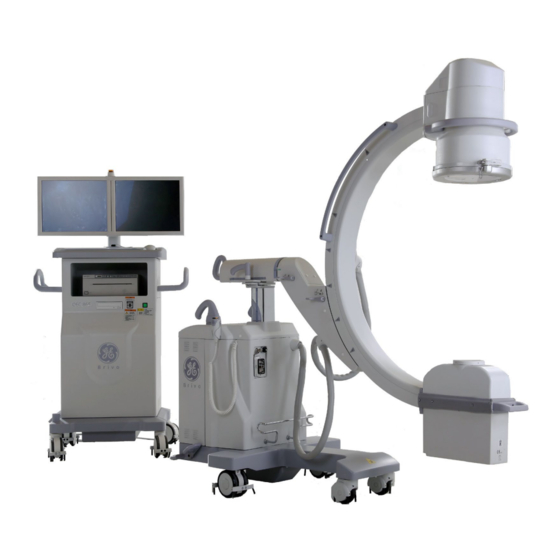
2.1. System Descriptions System overview Brivo OEC 715/785/865 Mobile C-Arm X-ray Product is intended to provide fluoroscopic and film imaging of the patient in diagnostic and surgical applications. Clinical applications may include, but are not limited to, orthopedic, Pain Management Procedures and General Surgery. Such users will use this system on a daily basis. - Page 57 System Overview ‒ Software Options: OptionBasicDicom, OptionDicomQ&R, OptionDicomMpps, OptionAnnotation, OptionMeasurement The C-Arms derive their name from the rigid, C-shaped weldment that supports the Image Intensifier, collimator, CCD Camera, and X-ray tube. These components together are commonly called the “C”, and the entire assembly from the casters up is known as the “C-Arm”. The X-Ray tube generates an X-ray beam that is shaped and oriented by the collimator.
-
Page 58: Component Locator
Brivo OEC 715/785/865 Mobile C-Arm X-Ray Product Service Manual Component Locator 1. Image intensifier and CCD camera 2. Lateral rotation movement brake handle 3. Orbital movement brake handle 4. Skin spacer 5. X-ray tube head (X-ray tube and collimator) 6. Front wheel 7. - Page 59 System Overview 1. Exposure indicator 2. Mouse 3. Cabinet for printer 4. USB connector 5. Power on/off 6. Universal wheel 7. LCD Monitors 8. Workstation membrane keyboard 9. DVD driver 10. Brake pedal 11. Central control wheel 12. Handles 13. Room Control Connector 14.
-
Page 60: System Block
Brivo OEC 715/785/865/865 Mobile C-Arm X-Ray Product Service Manual System block System Schematics please refer to appendix... -
Page 61: Subsystem
System Overview 2.2. Subsystem Power Distribution and Control Interlock In interlock loop, Interconnect Cable, Display Board, Collimator Control Board, Mainframe Control Board, Filament Driver Board, KV Control Board and Power Distribution Unit Board compose a safety loop. Once the interconnect cable between C-Arm and the Workstation is removed or any PCBs in C-Arm loose from slot due to collision or other unexpected situation, the relay K4 (on Power Distribution Unit Board) will not be energized so that the Mainframe can't be powered on. - Page 62 Brivo OEC 715/785/865/865 Mobile C-Arm X-Ray Product Service Manual Primary Common Mode Normal Mode Primary Inrush Voltage Voltage Side Current Mains power Surge Surge Of main Surge suppression suppression transformer suppression Drive circuit Interlock Signal System CMPTR +12V Signal User...
- Page 63 System Overview Power Output The two channel AC voltages are generated from this board and then apply to the main transformer primary side and mainframe accordingly. Grounding Connection In the PDU board there is an analog ground (AGND), digital ground (DGND) and a protective earth (PE). Function Implement The Power distribution Unit (PDU) board is mounted in the workstation and provides the controlled power for main transformer and mainframe.
- Page 64 Brivo OEC 715/785/865/865 Mobile C-Arm X-Ray Product Service Manual An Altera CPLD U1 is used as main controller on the board; it controls most of the relays on the board, generates the signal by the user interface and communicates with SIB board...
- Page 65 System Overview Timing Sequence Chart 220V_Power Air_break 350ms HW_SW Ups_ctrl CPTR_12V Heartbeat INTERELOCK = 1 Normal power on timing Normal power off timing Interface AC power input AC power input is listed as follows. Name Description Attribution Scale Comment PJ1-1 POWER AC power input for PJ1-2...
- Page 66 Brivo OEC 715/785/865/865 Mobile C-Arm X-Ray Product Service Manual Power Indicator interface The voltages used to control the power indicator are listed as follows. Name Description Attribution Scale Comment PWR_LED_L PJ1-5 Power Power indicator 100/110/120VAC PWR_LED_N PJ1-6 Power Main transformer primary side interface The voltages applied to the main transformer primary side are listed as follows.
- Page 67 System Overview Power on/off button interface The voltages applied to the power on/off button are listed as follows. Name Description Attribution Scale Comment SYS_ONOFF_CTRL_1 The button switch PJ5-1 Power 0/+12VDC SYS_ONOFF_CTRL_2 on/off terminal PJ5-2 Power 0/+12VDC BUTTON_LED_+12V The button PJ5-3 Power 0/+12VDC BUTTON_LED_GND...
- Page 68 Brivo OEC 715/785/865/865 Mobile C-Arm X-Ray Product Service Manual mainframe power detection MF_PWR PJ8-8 digital 0/+12V (>6V=High) signal connection status signal PDU_CONNECT_2 PJ8-9 digital 0/+12V (>6V=High) from PDU to SIB connection status signal PDU_CONNECT_1 PJ8-10 digital 0/+12V (>6V=High) from PDU to SIB...
- Page 69 System Overview CPLD_INTLC_BRD_A Interlock board signal CPLD_INTLC_CABLE_A Interlock cable signal AC Output of main transformer secondary side voltage divider DC output of line gain in RMS-DC conversion circuit TP10 The reference point of under/over voltage protection circuit TP11-TP15 Reserved test points for debug for CPLD TP16 SIB_INTLC_BRD Interlock board signal for SIB board...
-
Page 70: Mother Board
Brivo OEC 715/785/865/865 Mobile C-Arm X-Ray Product Service Manual Mother Board The Mother Board is installed in the E-box of the Main Frame; it is responsible for below three functions: Realize power and fuse allocation, Offer connectors for cables to or from Collimator, Display Board, KV Control Board, Sealing Board, I.I., Hand Switch, Footswitch, Emergency Key Switch, Filament, DC Power Supply Boxes, Laser Aimer, etc. -
Page 71: Mainframe Control Board
System Overview Mainframe Control Board The MCB (Mainframe Control Board) is located in C-Arm mainframe and is the main control unit in mainframe. It is responsible for five functions. X-ray control: KV, mA and exposure control interfacing with collimator board, filament board, and KV control board Image chain control: control camera and image intensifier User interface: key input and LED display interfacing with display board... - Page 72 Brivo OEC 715/785/865/865 Mobile C-Arm X-Ray Product Service Manual MCB functional Block MCU function Read the registers of peripheral controller to get the status of sub-systems, such as getting the alarm status, etc. Write the registers of peripheral controller to control the status of sub-systems, such as PIO (Programmable Input Output), light indicator, buzzer, etc.
- Page 73 System Overview Optical coupling Optical coupling circuit is responsible for changing voltage level and isolating the ground of circuit at each sides of optical coupler. DAC (Digital Analog Converter) circuit is responsible for output analog signal, such as KV setting, mA setting and mA pre-heat.
- Page 74 Brivo OEC 715/785/865/865 Mobile C-Arm X-Ray Product Service Manual Collimator Control Collimator control includes - Collimator Shutter open/close control - Collimator Shutter rotation control - Collimator Iris open/close control MCU gets user’s command from Control panel, and sends setting value of position information of Shutter and Iris to Collimator by SPI bus.
- Page 75 System Overview Digital signals LIH is through optical coupling circuit from Peripheral controller of MCB to Camera. Digital signal FRAME_SYNC is from Camera to MCB. It is the global synchronization signal of X-Ray control function, so it acts as clock and interrupt signal to peripheral controller and MCU, respectively. GAIN signal from MCB to camera is through RS485 bus.
- Page 76 Brivo OEC 715/785/865/865 Mobile C-Arm X-Ray Product Service Manual registers in MAX6954. Meanwhile, MCU changes the 7-segent LED display by writing the control registers in MAX6954. MAX7301 is a LED controller. Similarly to MAX6954, MCU changes the LED display by writing the control registers in MAX7301.
- Page 77 System Overview signals are output to KV control board and filament control board through DAC and operational amplifier circuit or PI circuit sequentially. Manual kV Setting Control panel samples the manual kV setting value, and transports it to MCU by SPI bus. MCU looks up the responding data and sets DAC circuit.
- Page 78 Brivo OEC 715/785/865/865 Mobile C-Arm X-Ray Product Service Manual Interface Overview MCB is plugged in Mother Board, and is connected with other sub-systems through Mother Board. The electrical interface of Mother Board, please refer to Motherboard section. The external physical interfaces of MCB are defined in the table below:...
- Page 79 System Overview KV Control Signals from MCB to kV control board are listed as follows. Name Description Attribution Scale Comment SAFETY_EN Safety line for EXPOSURE_COMMAND Digital 0/+15V J1-B19 +15V= effective EXPOSURE_EN Exposure command Digital 0/+15V J1-A17 +15V= effective KV_SET_INPUT KV set value to KV control board Analog 0-6V, Unit is 20KV/V J2-C10...
- Page 80 Brivo OEC 715/785/865/865 Mobile C-Arm X-Ray Product Service Manual FRAME_SYNC Frame synchronization signal from Digital 0V/+15V J1-B24 Camera. Frequency is 25Hz approximately GPIO_OUT2 General Purpose Output signal 2 Digital 0V/+15V J1-B21 Reversed for future from Camera GPIO_OUT3 General Purpose Output signal 3...
- Page 81 System Overview UDB_OVERCUR_N Over current error Digital 0-+15v J1-C9 0V= effective DOWN_PROTECT_TO_MCB_N Reach limit Digital 0-+15v J1-C10 0V= effective UP_TO_MCB_N UP key Digital 0-+15v J1-C8 0V= effective DOWN_TO_MCB_N DOWN key Digital 0-+15v J1-C20 0V= effective DOWN_SECURITY_TO_MCB_N DOWN_SECURITY key Digital 0-+15v J1-C21 0V= effective Workstation Communication...
- Page 82 Brivo OEC 715/785/865/865 Mobile C-Arm X-Ray Product Service Manual button has pressed HAND_HLF_SECURITY Hand security line Passive Open/Close J1-C27 termination HAND_HLF High Level Fluoro Passive Open/Close J1-B7 HAND_HLF & HAND_COM is hand switch connected means HAND_HLF termination button has been pressed...
- Page 83 System Overview switch1 connected means EMERGENCY_SWT has been pressed REF_ The other Passive J1-B11 EMERGENCY_SWT1 termination of Emergency switch1 EMERGENCY_SWT2 One termination of Passive Open/Close J1-C25 EMERGENCY_SWT2 & Emergency REF_EMERGENCY_SWT2 is not switch2 connected means EMERGENCY_SWT2 has been pressed REF_ The other Passive J1-A26...
- Page 84 Brivo OEC 715/785/865/865 Mobile C-Arm X-Ray Product Service Manual INTERLOCK_LOOP_B The other termination Passive J2-B15 MCB as part of the whole interlock of interlock loop loop. If connecter J2 of MCB is loose, the whole inter loop will be broken, Mainframe will power off.
- Page 85 System Overview D36 flickers when MCU work well SPI_SOMI. D37 flickers on MCB SOMI FRAME_SYNCH. D38 is flickering on MCB when FRAME_SYNCH is available FSYN FOOT_BUTTON2 & FOOT_COM. D39 turns off when press D40 turns off when FPGA configuration completes CONF D41 turns off when footswitch interupt signal is available to MCU FINT...
-
Page 86: Display Board
Brivo OEC 715/785/865/865 Mobile C-Arm X-Ray Product Service Manual Display Board Display board and membrane kit compose a whole control panel of C-Arm, installed in C-arm. Control panel kit receives user input command and sends signal to Mainframe Control Board. - Page 87 System Overview Signals connected to motherboard Name Description Attribution Scale Comment +5V_DB +5V from MCB DB15-1 Power GND_PS1 GND from MCB DB15-2 Ground SPI_CLK Provide MAX6954 &MAX7301 work clock DB15-3 Digital 38KHz SPI_CS2 MAX7301 select signal DB15-4 Digital 0/15V 0V=effective SPI_MOSI Communicate with MCB DB15-5...
- Page 88 Brivo OEC 715/785/865/865 Mobile C-Arm X-Ray Product Service Manual Signals connected to key scan interface Name Attribution Scale Comment Save DX3_1 Digital open/close close =effective swap DX3_2 Digital open/close close =effective mode DX3_3 Digital open/close close =effective Image_ rotate_ CCW...
-
Page 89: Keyboard Control Board
System Overview Keyboard Control Board The Keyboard Control Board is installed in the Workstation and acted as the translator between workstation membrane keyboard and workstation computer. It translates key press and release into make/break code that computer can identify. The interface and communication between KCB and computer conforms to standard USB 1.1 protocol. - Page 90 Brivo OEC 715/785/865/865 Mobile C-Arm X-Ray Product Service Manual Key allocation and make/break code The main control IC of the board is HT82K629A, a keyboard encoder. It can function both in USB and PS2 interface environment. What we apply in this...
-
Page 91: Updown Board
System Overview Updown Board Up/down Board is located in C-Arm mainframe and is the control and drive unit of the lift column motor. MF_AC2 MF_AC2 8V_L 8V_L MOTO1 Up/down relays MF_AC2 MF_AC2 MOTO2 Emergency Switch 8V_N 8V_N AC-DC Up/down Control Relays UP_N UP_N Motor Current... - Page 92 Brivo OEC 715/785/865/865 Mobile C-Arm X-Ray Product Service Manual THEORY OF OPERATION Power Regulator This circuit is to translate the DC24V input to the DC+15V and DC+2.5V which would be used in the updown board. Devices 7815 and LM431 are used to realize this function.
- Page 93 System Overview PMOSFET Driver This circuit is to control the PMOSFET so that the DC voltage would not higher than 37V+/-5%. When the DC voltage is higher than 37V+/-5% the PMOSFET would turn off. When the DC voltage is lower than 29V+/-5% the PMOSFET would turn on.
- Page 94 Brivo OEC 715/785/865/865 Mobile C-Arm X-Ray Product Service Manual Interface: AC power input The AC power input is listed as follows. Name Description Attribution Scale Comment MF_AC28V_L AC power input for motor J1-1 POWER 28V AC ---- MF_AC28V_N AC power input for motor...
- Page 95 System Overview Proximity switch interface The signals from the proximity switch are listed as follows. Name Description Attribution Scale Comment Proximity protecting signal DOWN_PROTECT J6-1 Digital 0V/+24V HIGH=Proximity protect from the proximity switch. Power to the proximity +24V_UDB J6-4 Power +24V ---- switch...
-
Page 96: System Interface Board
Brivo OEC 715/785/865/865 Mobile C-Arm X-Ray Product Service Manual System Interface Board The system interface board is mounted in the workstation and will provide the interface between user and system. It is responsible for 8 functions. Detect OR door open/close status and send it to WKS... - Page 97 System Overview Wireless Wireless Router Switch FPGA User Interface Ethernet Ethernet A and B Power Isolation WKS computer Interface: Power Interface The pin definition of power connector Name Description Attribution Scale Comment +5Vin_Cmptr +5V power Power 0/5.5V +5Vin_Cmptr +5V power Power 0/5.5V +12Vin_Cmptr...
- Page 98 Brivo OEC 715/785/865/865 Mobile C-Arm X-Ray Product Service Manual Door_Open_Active_A Input to show the status of door status Analog 0VAC/24VAC Input Door_Open_Active_B Analog PDU Interface Signals connected to PDU are listed as follows. Name Description Attribution Scale Comment Sys_Pwr_Req Power off requeset...
- Page 99 System Overview Ethernet Interface Signals connected to Ethernet Interface are listed as follows. Name Description Attribution From Comment CX1+ Ethernet CX1+ Differential S10 pin 11 S9 pin 11 CX1- Ethernet CX1- Differential S10 pin 10 S9 pin 10 CX2+ Ethernet CX2+ Differential S10 pin 4 S9 pin 4...
- Page 100 Brivo OEC 715/785/865/865 Mobile C-Arm X-Ray Product Service Manual LED12 T_LED1 LED13 T_LED2 LED14 T_LED3 LED15 T_LED4 LED16 XRAY_ON_CMD_FB High=effective LED17 ROOM_IN_USE_CMD_FB High=effective LED18 WIRELESS_PWR_CMD_FB High=effective LED19 DOOR_OPEN_ACTIVE LED20 ACK_PDU2SIB_FPGA Low=effective 2-46...
-
Page 101: Collimator Control Board
System Overview Collimator Control Board Mother board +15V -15V +5V ERROR POWER SUPPLY INDICATORS MOT_IRIS+ IRIS MOT_IRIS- IRIS IRIS IRIS Analog Driver SCLK SYNC MOT_ROT+ DAC with IRIS Analog MOT_ROT- control Driver Collimator MOT_WIDTH+ WIDT IRIS WIDTH WIDTH Analog MOT_WIDTH- Driver IRIS_POSN ROT_POSN... - Page 102 Brivo OEC 715/785/865/865 Mobile C-Arm X-Ray Product Service Manual Communication with MCB and Collimator DAC7554 is used to output 3 analog channels and its control accuracy is 12-bit. It shall be controlled by MCB through SPI, in order to generate collimator-motor- target-position control signal. There are 3 motors in collimator, which are IRIS motor, shutter width motor and shutter rotation motor.
- Page 103 System Overview Test Point TP refer Signal +5V analog -15V Shutter rotation motor control after PI adjustment Shutter width control after PI adjustment IRIS control after PI adjustment IRIS position after filter TP10 Shutter width position after filter TP11 Shutter rotation position after filter TP12 Shutter rotation motor control+ TP13...
-
Page 104: Kv Control And Igbt Assembly
Brivo OEC 715/785/865/865 Mobile C-Arm X-Ray Product Service Manual kV control and IGBT assembly KV Control Board The kV control board is mounted inside the C-Arm Mainframe. It is one part of X-ray generator. The kV control board will provide the following functional and performance. - Page 105 System Overview - Dual Source/Sink Outputs: ±400 mA Peak The switch frequency is 40KHz for X-ray generator. So the SG3525 should provide 40KHz PWM signal. Frequency is determined by adjusting the resistor connected with pin6 and capacitor connected with pin5. At this pin5 80KHz swath wave should be observed in oscillograph.
- Page 106 Brivo OEC 715/785/865/865 Mobile C-Arm X-Ray Product Service Manual For the higher protect circuit point the value is set 120kV. When kV feedback signal KV- or kV+ is higher than reference value in U10-2 and U11-2 the STOP signal is activated. At the same time led DS5 lightens. Jumper W1 can disable this protect circuit.
- Page 107 System Overview IGBT Board Main Rectifier DC bus transformer bridge capacitor Resonant Drive power kV Control Monoblock circuit transformer board Signals from MCB to KV control board are listed as follows. Name Description Attribution Scale Comment SAFETY_EN Safety line for EXPOSURE_COMMAND Digital 0/+15V +15V=enable...
- Page 108 Brivo OEC 715/785/865/865 Mobile C-Arm X-Ray Product Service Manual TP16 The sample voltage of DC bus over-voltage protection TP17 The sample voltage of DC bus low-voltage protection TP18 Divided DC bus TP19 Optocoupler output of DC bus TP20 TP21 TP22...
-
Page 109: Filament Driver Board
System Overview Filament Driver Board The filament current sense circuitry uses hall current sensor to provide analog output proportional to the actual filament transformer current. The FDB is mounted in the Mainframe E-box. It is responsible for several functions as follows: Provide PWM output for driving Filament Transformers in High Voltage Tank Switch large or small filament focus Stop PWM generation for a while delay when switching large or small filament... - Page 110 Brivo OEC 715/785/865/865 Mobile C-Arm X-Ray Product Service Manual Pulses PWMA and PWMB are produced by SG3525, pulse width modulator control integrated circuits. Installed on J5 or J6 by jumper, compatible old Monoblock (without blue mark) and new Monoblock (with blue mark).
- Page 111 System Overview When filament focus switches, PWM pulses will shut down for a while delay of 56mS, because operate time of relay is about 7mS and RC circuit of coil of relay costs about 6mS. The delay time should be more than 13mS.
- Page 112 Brivo OEC 715/785/865/865 Mobile C-Arm X-Ray Product Service Manual SMAC_V PWM control voltage -15V Power +24V TP10 Power TP11 PWM control voltage TP12 Power TP13 crystal oscillator output PWMA TP14 PWM drive signal TP15 TP16 24V_GND TP17 GND of 24V...
-
Page 113: Monoblock
System Overview Monoblock Monoblock can generate X-ray. It mainly consists of high voltage generator and tube insert. All high voltage components are put into oil box, which can enhance the insulation performance. Monoblock generates 110kV inside the oil tank. The input voltage changes from 0V to 240V peak value. High voltage is got from high frequency and high voltage transformer T1. - Page 114 Brivo OEC 715/785/865/865 Mobile C-Arm X-Ray Product Service Manual Signals from sealing board to MCB: Name Description Attribution Scale Comment OIL_TEMP Output voltage of Analog 0-5V temperature sensor OIL_TEMP_GND Reference of OIL_TEMP Ground THERMAL_SWITCH_A One termination of Passive THERMAL_SWITCH_A &...
-
Page 115: X-Ray/Key Switch And Emergency Switch
System Overview X-Ray/key Switch and Emergency Switch Key switch is used to control the unauthorized usage of X-ray exposure and vertical lift motor. Signals from Key switch to Mainframe Control Board: Name Description Attribution Scale Comment XRAYOFF The termination which Passive Open/Close XRAYOFF &... - Page 116 Brivo OEC 715/785/865/865 Mobile C-Arm X-Ray Product Service Manual connected means FOOT BUTTON 1 has been pressed FOOT_BUTTON2 Button 2 Passive Open/Close J1-A19 FOOT_BUTTON2 & FOOT_COM is connected means FOOT BUTTON 2 has been pressed FOOT_COM Common Passive J1-B32 termination Emergency switch, located on the control panel of C-arm mainframe, stops all motorized motion immediately, interrupts any X-rays in progress, and prevents further X-rays until you reset the system.
-
Page 117: Image Chain
System Overview Image Chain Overview The following diagram is the image chain pipeline of Brivo715/785/865. X-ray Generation X-ray Detection Image Acquisition Image Processing Image Display Digital 12 bit Digital Digital Left 19" X-ray GigE Network X-rays X-rays Light Gigabit Lan 12 bit 8 bit color/mono... - Page 118 Brivo OEC 715/785/865/865 Mobile C-Arm X-Ray Product Service Manual Mother Board Command Drive Ref voltage Collimator Position Position There is an independent control loop working for each motion. The negative feedback control loop is used. E.g. for iris control, the following steps will be operated: Firmware in MCB sends a command to CCB by SPI bus to tell the required position of iris.
- Page 119 Useful entrance field size Output image diameter 25.2 Center Limiting resolution lp/cm DQE at 59.5 keV- absolute (IEC) GIGE Camera There are four kinds of GigE Camera for Brivo OEC 715/785/865. Comments Name 5075006 GigE Camera AM1565 For 715/785 5085003...
- Page 120 Brivo OEC 715/785/865/865 Mobile C-Arm X-Ray Product Service Manual 5491850, 5491851 and 6491850 share common electrical parts and they are different on optics lens and relative mechanical parts. GigE Camera GE1020A GigE Camera GE1020B GigE Camera GE1020C GigE Camera is above Image Intensifier. It takes the image from the output of Image Intensifier. The following are the main functions of camera: •...
- Page 121 System Overview GigE Camera use CCD sensor to acquire image on the output window of image intensifier. Following table shows the key specification of CCD sensor. Key Specification of CCD sensor of 5075006 and 5085003 Specification Description Image size Diagonal 11 mm (Type 2/3) Active pixels number 1360 (H) ×...
- Page 122 Brivo OEC 715/785/865/865 Mobile C-Arm X-Ray Product Service Manual There are two connectors in GigE camera. One is industrial standard RJ-45 connector for GigE Vision Protocol on Gigabit Ethernet, IP: 192.168.42.239. The other is HDB15 female connector which provides power, RS422 and GPIO as following Table:...
- Page 123 System Overview 3D 500025 Lens GigE Camera AM1565B uses an interface flange for mounting itself into image intensifier. This interface flange is integrated into lens. This interface flange provides three holes for mounting camera with image intensifier, at the same time it provides 6 screws around flange to position the image center for accommodating errors of at least 2 mm.
- Page 124 Brivo OEC 715/785/865/865 Mobile C-Arm X-Ray Product Service Manual GigE Camera GE1020A uses an interface flange for mounting itself into image intensifier. This interface flange is independent part from lens. This interface flange provide three holes and these holes accommodate errors of at least 2 mm for positioning the image center.
- Page 125 System Overview GigE Camera GE1020C uses Computar M1614-MP lens. This lens has 16mm focal lens, manual iris F1.4-F16 and manual focus. GigE Camera GE1020C uses an interface flange for mounting itself into image intensifier. This interface flange is independent part from lens. This interface flange provide three holes and these holes accommodate errors of at least 2 mm for positioning the image center.
- Page 126 Exposure Factor means the ratio between the Indicated value of the total radiation without an Anti-scatter Grid in a specific beam of radiation and that with the Anti-scatter Grid placed in the beam. Setup points: No setup points available. Monitor There are 4 kinds of monitor for Brivo OEC 715/785/865. Comments Name 5075503...
- Page 127 System Overview Following is 5085503’s specification: Item Specification Size 19.0” Aspect Ration Resolution 1280 x 1024 dots (SXGA) Maximum Brightness 800 Cd/m2 (min) Contrast 600:1(min) Viewing Angle 170 degree 170 degree Video Input Signal DVI-D, VGA Control key Menu, up, down, exit Backlight, Black level, Contrast, Brightness level, Position, Size, Function Phase, Gamma, DICOM etc.
- Page 128 Brivo OEC 715/785/865/865 Mobile C-Arm X-Ray Product Service Manual Backlight, Black level, Contrast, Brightness level, Position, Size, Function Phase, Gamma, DICOM etc. Preset Brightness 500±20 Cd/m2, 600±20 Cd/m2, 700 ±20 Cd/m2 Preset Display Curve DICOM, CIE, Gamma 1.8, Gamma 2.0, Gamma 2.2(default).
-
Page 129: Computer And Peripheral
System Overview Computer and Peripheral Computer The computer mounted inside the workstation takes over most process of the system. It communicates with external devices, receives image from GigE camera, process, display and save image. Following is the configuration of computer. Comments Name Configuration... - Page 130 Brivo OEC 715/785/865/865 Mobile C-Arm X-Ray Product Service Manual DVD and USB A CD/DVD RW Drive is optional and mounted in the front of workstation. It connected to computer rear plane with a SATA interface and power cable. The CD/DVD RW drive can archive images inside hard disk, it supports the following writing media: •...
-
Page 131: Ups
System Overview There are one external UPS in system to protect computer and right monitor in case of AC lost accidently, left monitor is not protected by UPS, so when AC lost accidently, user still can see the content of right monitor while left monitor is blackout. UPS output capacity is 550VA/330W, and can provide at least 2 minutes for computer and right monitor so that system can shutdown computer safely. - Page 132 Brivo OEC 715/785/865/865 Mobile C-Arm X-Ray Product Service Manual Operation of UPS Display interface On Line—The UPS is supplying utility power to connected equipment Power-Saving—Master and controlled outlets are enabled, saving power when the master device goes into sleep or standby mode Load Capacity—The load is indicated by the number of sections...
- Page 133 2. Press and hold the POWER button for six seconds. The LOAD CAPACITY bar will flash on and off, indicating that the unit is in programming mode. 3. Press POWER again to rotate through the menu options. Stop at selected sensitivity. The unit will beep to confirm the selection. The Medium sensitivity is the model used in Brivo OEC 715/785/865 2-79...
- Page 134 Brivo OEC 715/785/865/865 Mobile C-Arm X-Ray Product Service Manual Warnings and System Faults Warnings: Press DISPLAY to scroll through the display screens. System Faults: 2-80...
- Page 135 System Overview Function Button Quick-Reference Function Button Timing Status Description (seconds) Power Power On Press POWER to start receiving input utility power. If A/C input power is not available, the unit will run on battery power. Power Off The unit is not receiving input utility power, but is providing surge protection.
- Page 136 Brivo OEC 715/785/865/865 Mobile C-Arm X-Ray Product Service Manual Troubleshooting Problem Possible Cause Corrective Action Back-UPS will not switch The unit is not connected to utility power. Ensure that the unit is securely connected to an AC outlet The circuit breaker has been tripped.
-
Page 137: Chapter3
Chapter3. Installation... -
Page 138: Overview
Brivo OEC 715/785/865 Mobile C-Arm X-Ray Product Service Manual 3.1. Overview This chapter describes the installation procedure of Brivo OEC 715/785/865 Mobile C-Arm X-ray Product. 3.2. Pre-Installation 3.2.1. Dimensions and Weights of System Dimensions: C-Arm: Hmax/Hmin L=215/170.5cm 78cm 179cm (84.6’’/67.1”... -
Page 139: Power Supply Requirement
Installation 3.2.3. Power Supply Requirement Voltage: AC 100V/110V/120V|200V|220V/230V/240V± 10% Frequency: 50Hz/60Hz± 3Hz Rated Momentary Line Current (shorter than 5s): • 30A (100V/110V/120V) • 28A (200V) • 25A (220V/230V/240V) Rated Continuous Line Current: • 20A (100V/110V/120V) • 12A (200V) • 10A (220V/230V/240V) Maximum line impedance: 0.3Ω|0.6Ω|0.6Ω... -
Page 140: Tools And Test Equipment
Brivo OEC 715/785/865 Mobile C-Arm X-Ray Product Service Manual 3.2.5. Tools and Test Equipment Standard Tools and Test Equipment are required to install the system. In addition to standard service tools and test equipment, the following special tools and standard test equipment are required to complete this procedure. -
Page 141: Unpacking
Installation 3.3. Unpacking There are 2 packages for Brivo OEC 715/785/865 Mobile C-Arm X-ray Product. One is for C- Arm (L H=2000mm 900mm 1995mm. And the other is Workstation (L × × × × × × H=1015mm 900mm 2150mm). ×... -
Page 142: Unpack C-Arm
Brivo OEC 715/785/865 Mobile C-Arm X-Ray Product Service Manual 3.3.2. Unpack C-Arm Place the C-Arm and workstation packages on the flat and leave enough space around. Cut off the binding tie and remove the cardboard coping and box of the C-Arm. Then remove the seal wrapper of the C-Arm. - Page 143 Installation Fasten the jackscrew to lift the back of mainframe to remove the wood support, as above picture. After removing the wood support, release central screw to land steering wheels on pallet, and then remove the metal bracket. Lock the steering brake before release the central screw. Don’t pry the side the side metal cover of Mainframe...
- Page 144 Brivo OEC 715/785/865 Mobile C-Arm X-Ray Product Service Manual Remove the secure screws of the metal bracket and wood support, as below picture. Use wood crowbar prize the front base of C-Arm to remove the wood support as below picture.
- Page 145 Installation Hold the handles and move the C-Arm backward to draw out backwards the image intensifier and Monoblock. Take care to protect the Image intensifier and grid when moving the C-Arm. Remove the localizer frame of Image intensifier and Monoblock, before moving the C-Arm backward.
-
Page 146: Unpack Workstation
Brivo OEC 715/785/865 Mobile C-Arm X-Ray Product Service Manual 3.3.3. Unpack Workstation Cut off the binding tie and remove the packing of the workstation. Take out the ramp on standby. And remove the wrapper on the workstation. Remove all the screws on the wood support on both sides. - Page 147 Installation Put the ramp in position. Release all bracket and move the workstation along the ramp off the pallet. 3-11...
-
Page 148: System Inspection
Brivo OEC 715/785/865 Mobile C-Arm X-Ray Product Service Manual 3.4. System Inspection 3.4.1. Label Inspection After the system installation, check and verify that all labels in section 1.2.11 should be in position. Following labels should be in local language according to the regulation requirement. - Page 149 Installation System rating plate indicates manufacture information and input power requirements. Check the rating plates to ensure mainframe and workstation serial numbers matched. Generator tube head rating plate. 3-13...
- Page 150 Brivo OEC 715/785/865 Mobile C-Arm X-Ray Product Service Manual This is the label of collimator. This label warns the operator or the patient not to look at the laser beams directly. (The label will only be required if there is laser aimer.)
- Page 151 Installation Image Intensifier label for Brivo OEC 865. Image Intensifier label This warning label is on the Workstation front cover. 3-15...
-
Page 152: External Inspection
Brivo OEC 715/785/865 Mobile C-Arm X-Ray Product Service Manual 3.4.2. External Inspection Cabling and Connector inspection Check the interconnect cable for damage or other problems. Verify that connector on cable mates well with the connector on C-Arm and that there are no bent or missing pins. Make sure the strain relief attaches securely to both the interconnect cable and connector. -
Page 153: Internal Inspection
Installation Workstation Inspection Inspect each workstation component listed under the heading workstation inspection. Select one check box for each item in the list. WorkStation Inspection list: Physical Location No problem Loose or missing Broken or Chipped or found parts damaged parts scratched paint Monitor and Arm Keyboard... -
Page 154: System Setup
Brivo OEC 715/785/865 Mobile C-Arm X-Ray Product Service Manual 3.5. System Setup 3.5.1. Power Supply Adaption If your power supply is 100V/110V/115V/120V/200V/220V/230V/240V, please follow steps below to change power supply. Otherwise, go to section3.5.2. 1. Make sure that workstation rear cover was removed. -
Page 155: Ups Setup
Installation The system can adapt power supply of AC100V, AC110V, AC115V, AC120V, AC200V, AC220V, AC230V and AC240V by different connections of the transformer. Before install the system, please check the power supply voltage range and the transformer connection per the diagram below. Wire Transformer taps Voltage... - Page 156 Brivo OEC 715/785/865 Mobile C-Arm X-Ray Product Service Manual 3. Lay UPS on side as below picture and remove the battery cover (battery cover is under UPS). 4. Pull out the battery of UPS and plug the power supply cable into the power pin of UPS box.
-
Page 157: System Power On
The auto fluoroscopy mode is selected and the power on indicator lights. The field size is in Normal mode. The left monitor of workstation will display GE logo screen. The right monitor will enter into the User login Screen automatically. -
Page 158: System Configuration In Admin Interface
Brivo OEC 715/785/865 Mobile C-Arm X-Ray Product Service Manual 3.5.5. System Configuration in Admin Interface Setup in Admin Interface by Service Authority 1. Hold down “Ctrl +Shift+Alt” and”→ ” keys at same time to invoke Admin Interface. Select Service as User, and then input password to Login Service Tool Interface. - Page 159 Installation 1. Press the “Setup” key on the Workstation membrane keyboard or select the “Setup” button on the system panel in software interface to access setup features. 2. Select “Date Time & Region” button to setup: Date Time Time Zone ...
- Page 160 Brivo OEC 715/785/865 Mobile C-Arm X-Ray Product Service Manual 3. Select “C-Arm System” button to setup: Hospital Name Retain Last Exam Change or Boot up Screen Saver Auto Save at End of Exposure Auto swap ...
-
Page 161: Dicom Setup And Check
Installation 3.5.6. DICOM Setup and Check You can choose the verification items from DICOM Worklist server, storage server and printer server, according to the customer’s network situation and equipment. Feature for DICOM, available DICOM features are displayed in Product config/Software Option List, in this section just setup and check the option purchased by customer: OptionBasicDicom (Contains: DicomWorklist/DicomStorage&Commitment/DicomPrint) OptionDicomQ&R, OptionDicomMpps. - Page 162 Brivo OEC 715/785/865 Mobile C-Arm X-Ray Product Service Manual DICOM Printers setup and check DICOM Printers setup: Click “DICOM printers” Tab on setup screen. Click “Add…” button into Add interface. Fill in the information of the DICOM printers.
- Page 163 Installation DICOM printers function Check: Press Image Directory key on the workstation keyboard. Select DICOM printer server from the Print screen. Click the preview image and then click the queue box. Click “Print” button. Verify that the images can be printed successfully after the process complete.
- Page 164 Brivo OEC 715/785/865 Mobile C-Arm X-Ray Product Service Manual Worklist Check: Click Press key to enter Exam Management screen. Click “Schedule…” button to enter Schedule Exam screen. In Schedule Exam screen, check the radio button of Worklist Server and select target Server, click “Quick Query”...
- Page 165 Installation Add and edit screen of Storage & Commitment Servers Storage & Commitment Servers Function Check: Press Image Directory button. Select DCIOM Storage Tab. Click “Export” Tab. In Store to pull down menu, select available Select the DICOM storage device.
- Page 166 Brivo OEC 715/785/865 Mobile C-Arm X-Ray Product Service Manual box is checked. 7. Query & Retrieve Setup and Check Query & Retrieve setup: Click “Query & Retrieve” Tab on setup screen In local settings, setup local transport parameters: Local Listening Port ...
- Page 167 Installation Query & Retrieve function check: Press key to enter Query & Retrieve screen. Select target Server and input filter option for Query, then click Query button. The target patient data will be displayed in Query Results. Select target patient data in ...
- Page 168 Brivo OEC 715/785/865 Mobile C-Arm X-Ray Product Service Manual MPPS function check: New an exam, take exposure and save several images. In Image Directory : Exam Status: In progressing MPPS Status: Unreport Click Report MPPS button: Exam Status: In progressing...
-
Page 169: Dicom Worksheet
Installation 3.5.7. DICOM Worksheet Record Network & DICOM information below: Station Name: Enter information into “Network & DICOM” screen. AE Title: Enter information into “Network & DICOM” screen. Local Network: Wireless Network: Does this site use DHCP? Does this site use DHCP? IP Address: IP Address: Enter information into “Network &... - Page 170 Brivo OEC 715/785/865 Mobile C-Arm X-Ray Product Service Manual Layout 3: 1×1 1×2 2×1 2×2 2×3 3×3 3×4 4×4 4×5 5×4 Layout 4: 1×1 1×2 2×1 2×2 2×3 3×3 3×4 4×4 4×5 5×4 Will the site use DICOM Worklist Server? If yes, record their configuration here.
- Page 171 Installation Will the site use Query & Retrieve? If yes, record their configuration here. Query & Retrieve Server Server Alias: AE Title: IP Address: Time Out Port Number: Information Model Study Root Patient Root Local Settings: Local Listening Port: Time Out: Days to Cache Retrieved images: Will the site use MPPS Feature?
-
Page 172: Functional Checks
Brivo OEC 715/785/865 Mobile C-Arm X-Ray Product Service Manual 3.6. Functional Checks 3.6.1. Workstation Checks Mechanical Movement Check: 1. Push the workstation and verify that the wheels roll smoothly without vibration and that they are securely attached to the wheels. - Page 173 Installation 5. Verify the DICOM Q/R function ( ) allows you to enter Q/R screen, if customer purchase the option. 6. Verify the SETUP function ( ) allows access to the Setup screen. Press “Security” button and select “Require Users to Login” in the screen. 7.
- Page 174 Brivo OEC 715/785/865 Mobile C-Arm X-Ray Product Service Manual 15. Verify ZOOM function ( ) displays a square region of interest (ROI) box and that you can magnify the ROI. 16. Verify SAVE function ( ), press the SAVE key. And then press key.
-
Page 175: C-Arm Checks
Installation CD/DVD check: CD/DVD is an option. This procedure is just performed on the system with this option. 1. Place a blank CD or DVD in the in the CD/DVD drive and wait for the green LED on the front of the drive to turn off. - Page 176 Brivo OEC 715/785/865 Mobile C-Arm X-Ray Product Service Manual 1. Release the orbital brake. 2. Verify that C-Arm orbits smoothly in its cradle without excessive play. 3. Verify that the entire orbital scale is readable and in good condition. 4. Set the brake handle to lock position and verify that C-Arm locks firmly in position.
- Page 177 Installation The following procedure produces X-rays. Use the appropriate personal protective WARNING equipment to protect yourself from X-ray exposure. Image Orientation Using the line pair tool as a phantom, take exposure in normal Fluoro mode and verify the following functions: •...
- Page 178 Brivo OEC 715/785/865 Mobile C-Arm X-Ray Product Service Manual Pulse Fluoroscopy Select Pulsed normal Fluoro mode via the C-Arm control panel. The X-Ray Exposure indicator keeps lighting when taking an exposure. If the pulse mode is enabled, the amount of accumulated time will be the actual exposure time, which depends on the time of pressing X-ray switch, length of pulses and the number of pulses per second.
- Page 179 Installation Manual HLF Select manual HLF mode. Take exposure and verify that a HLF exposure is taken. Verify that audible tone beeps at normal rate. Auto HLF and Digital Spot This key is only effective in some countries. In the other countries, invalid key sound will be given when pressing this key.
- Page 180 Brivo OEC 715/785/865 Mobile C-Arm X-Ray Product Service Manual Press the Auto/Manual Smart Metal key to reduce the appearance of metal in the image. It could provide optimum image quality even when metal is introduced to the field. Save. Press the “Save”...
-
Page 181: Auto Technique Tracking
), and the NORM field size to take an exposure. Put the copper filter on the Monoblock head. Verify that the kVp changes accurately as copper filters are inserted into the field in the following ranges: Model Copper Filter Thickness Brivo OEC 715/785 kVp range 64±4kVp 74±4kVp 82±4kVp (I.I PN: 5075001):... -
Page 182: Image Resolution
Brivo OEC 715/785/865 Mobile C-Arm X-Ray Product Service Manual 3.6.4. Image Resolution Place spatial resolution tool in the front of the image intensifier. The angle between the horizontal axis of the image and the resolution tool must be 45°. Select appropriate kV value. Take an exposure and stop once image is stable. -
Page 183: Beam Alignment Check
Installation Low dose Fluoro Dose rate check: 1. Position the detector of dosimeter at the center of the X-ray beam 30cm above the grid of image intensifier. Cover the image intensifier with lead plate thicker than 3mm. 2. Set kVp as 110kVp, increase mA to maximum in manual mode. Measure the dose rate while making exposure. -
Page 184: Fill In The Product Locator Card
Brivo OEC 715/785/865 Mobile C-Arm X-Ray Product Service Manual 3.6.9. Fill in the Product Locator Card After the installation, please fill in the product locator card for PLC parts below and mail the cards to local service operation office. Item Part Number... -
Page 185: Options Installation
Installation 3.7. Options Installation 3.7.1. CD/DVD Burner Installation 1. Power off system. SATA & SIB power interface board 2. Remove Worstation back, low side and front covers. 3. Open the computer cover and install the SATA & SIB power interface board. 4. -
Page 186: Laser Aimer
Brivo OEC 715/785/865 Mobile C-Arm X-Ray Product Service Manual 9. According CD/DVD check procedure check CD/DVD function (Refer to CD/DVD check of 3.6.1 Workstation Check) and reinstall workstation covers. 10. Reinstall the computer cover and Workstation covers. 3.7.2. Laser Aimer Laser Aimer on Monoblock 1. - Page 187 Installation 4. Press the laser aimer’s green ON switch to generate the laser beam. 5. Loose the set screw a little inside so that you Set Screw can adjust the beam by the adjuster. Circle adjuster 6. Adjust the adjusters of the laser until the intersection of the laser beam is in the center circle of the beam alignment tool.
- Page 188 Brivo OEC 715/785/865 Mobile C-Arm X-Ray Product Service Manual When the laser aimer is attached to the C-Arm, releasing the orbital or rotational brake could cause the C-Arm to move. Make sure to hold the C-Arm to control its movement CAUTION whenever a brake is released.
-
Page 189: Video Distributor
Installation 3.7.3. Video Distributor The video distributor provides DVI-D (DVI-Digtal) Video output Signal, So only the DVI-I and DVI-D connectors are available as the DVI Video output connector. DVI-I(Available) DVI-D(Available) DVI-A(Non-available) Following convertor list is provided as frequently-used type for reference. Convertor type Available or Not DVI-D to HDMI Convertor... - Page 190 Brivo OEC 715/785/865 Mobile C-Arm X-Ray Product Service Manual Put the video distributor on the backboard and fixed video distributor in workstation cabinet. Connect video cable firstly, then fasten the 4 secure screws to fix video distributor. Video cable (PN:...
- Page 191 Installation Functional check: Power on the system. Check that the left monitor will display GE logo screen. Disconnect and pull out the left monitor video cable then connect to OUTPUT1 and OUTPUT2 respectively. Verify that the left monitor will display GE logo screen in each case.
- Page 192 Brivo OEC 715/785/865 Mobile C-Arm X-Ray Product Service Manual DVI Output DVI Input Power 5. Connect video cable (PN: 5085792) of Video distributor to DVI output of computer. 6. Remove cable (PN: 5085729), connect power cable PN: 5085793 to computer power out, reconnect connector of SIB/PDU.
-
Page 193: Printer
Installation 3.7.4. Printer Brivo OEC 715/785/865 offers below printers as options: • UP-990AD Thermal Printer • UP-D897 Thermal Printer • UP-971AD Thermal Printer • UP-D898MD Thermal Printer Brivo OEC 715/785/865 is also compatible with below printers. • UP-970AD Thermal Printer •... - Page 194 Brivo OEC 715/785/865 Mobile C-Arm X-Ray Product Service Manual Connect the wires to the terminal blocks at the bottom of the workstation (connect the L line (brown) to connector 17 or 18 or 19, N line (blue) to 20 or 21 or 22 and the ground line (yellow and green) to earth port.
-
Page 195: Film Cassette Holder
Installation Press the menu button and scroll down or up to select corresponding legacy driver for new Sony printer. DRV: 897 for UP-D898MD/ UP-X898MD DRV: 970 for UP-971AD DRV: 990 for UP-991AD Functional check: Power on the system. Set the switch at back of printer to digital mode. Turn on the printer. -
Page 196: Tube Skin Spacer
Brivo OEC 715/785/865 Mobile C-Arm X-Ray Product Service Manual The cassette holder uses friction to hold the cassette. Verify that cassette is held securely within the cassette holder. Unsecured film cassettes WARNING may fall, injuring patients or personnel. 4. Remove the film cassette by pushing the cassette out of the cassette holder. -
Page 197: Pedal Switch
3.7.7. Pedal Switch Brivo OEC 715/785/865 Mobile C-Arm X-ray Product provides 4 pedal switches as option. Dual pedal switch with save button and 10m cable Dual pedal switch with save button and 5m cable Dual pedal switch with 8m cable ... -
Page 198: Removable Grid
Brivo OEC 715/785/865 Mobile C-Arm X-Ray Product Service Manual Removable Filter Sensor 5. Paste the multi language label on the filter. 6. Install the filter. Have the filter locked by the bolt of collimator top cover, by turn the filter clockwise. - Page 199 Removable Grid Support Carbon Protection Board 45° 60° Grid for Brivo OEC 715, Brivo OEC 785 Grid for Brivo OEC865 White dot is the direction mark for Grid. White dot is the direction mark for Grid. The connected line of direction mark is The connected line of direction mark is 60 in45°with C-Arm, in Brivo OEC715/785.
-
Page 200: Wireless Dicom
Brivo OEC 715/785/865 Mobile C-Arm X-Ray Product Service Manual Ensure the localizer bolt of Removable Grid Holder in the slot of image intensifier. Install Grid on removable grid hold and ensure the direction of grid as below picture. For Brivo OEC 715/785 For Brivo OEC865 60°... - Page 201 Installation Treadle bars Card pusher Ethernet card Release the 4 secure screws of Workstation cabinet, release the cables connect System Interface Board and pull out the cabinet. Route and connect WiFi power supply cable to WiFi adapter and J5 (on System Interface Board in Workstation cabinet) Route and connect power switch cable to power switch and J8 (on System Interface Board in Workstation cabinet).
- Page 202 Brivo OEC 715/785/865 Mobile C-Arm X-Ray Product Service Manual Remove the WiFi power switch baffle and install the WiFi adapter power switch in Workstation cabinet back plate. Connect the power switch cable to power switch in any Brown/Blue sequence. Wireless power switch baffle Reconnect cables of system interface board.
- Page 203 Installation 15. Power off system. 16. Unplug Ethernet cable from laptop/computer. 17. Route Ethernet cable in Workstation and plug Ethernet cable into Ethernet card. 18. Re-install all covers removed in step 1. 19. Affix the WiFi label and FCC label on the Workstation cabinet as shown below: WiFi Label FCC Label 20.
- Page 204 Brivo OEC 715/785/865 Mobile C-Arm X-Ray Product Service Manual 22. In “Network & DICOM” Tab, click “Configure…” The Smart Wizard will detect available wireless networks, and display the wireless list . 23. Select the corresponding router, click “Continue” button and input password. Click “Continue” button to complete the Wireless setting.
- Page 205 Installation The Wireless adapter will take several minutes to boot up. The wireless setting can only be configured after the adapter is booted up completely. Power indicator in orange means adapter is booting up. Power indicator in green means adapter has booted up completely, and can be configured. Booting Booted up FCC ID is recorded on the label located on the underside of the Wi-Fi internet adapter.
-
Page 206: Mono Lcd Monitor Installation
Brivo OEC 715/785/865 Mobile C-Arm X-Ray Product Service Manual 3.7.11. Mono LCD monitor installation Refer to Chapter 7 to install the Mono monitor. 3.7.12. Software Option Installation Refer to Chapter 5 to install software option function. It can be implemented in 3.5.5 System Configuration together with product model configuration. -
Page 207: Fill In The Product Locator Card For Option
Installation For Room Interface (RIF) connection, the rules listed below shall be complied with: 1. All equipment and power connect to RIF shall be UL/IEC60601 certified. Room In Use Indicator 2. For “Room in Use Indicator”, the Room Interface power shall be less than DC 36V, and Power<36V current shall be limited within 2A. - Page 208 Brivo OEC 715/785/865 Mobile C-Arm X-Ray Product Service Manual 5496967 LASER AIMER BS PRODUCT, English 5507689 LASER AIMER BS PRODUCT, Brazil Portuguese 5507504 LASER AIMER BS PRODUCT, China 5507653 LASER AIMER BS PRODUCT, Italian 5507657 LASER AIMER BS PRODUCT, French...
-
Page 209: Installation Check List
Installation 3.8. Installation Check List Brivo OEC 715/785/865 Installation Checklist Administrative Information Medical Facility Information Field Service Engineer Information Hospital or Clinic Name: FSE name: Address: City: Employee SSO: State: Country: Service Report Number: Postal Code/Zip: Contact Person: Date Installation Start/Complete:... - Page 210 Brivo OEC 715/785/865 Mobile C-Arm X-Ray Product Service Manual Auto Technique Tracking Image Resolution Specification Specification (kVp) (LP/mm) Copper Measured Adjustment Mag Mode Measured Adjustment Filters 715/785 715/785/ (kVp) done? (Field Size) (LP/mm) done? (mm) (II PN: 865 (I.I PN: (I.I PN:...
-
Page 211: Reporting
Installation 3.9. Reporting For U.S. Systems Complete and submit Form 2579 within 15 days of installation. 3-75... -
Page 212: Chapter4
Chapter4. Calibration... -
Page 213: Overview
Brivo OEC 715/785/865 Mobile C-Arm X-Ray Product Service Manual 4.1. Overview The Calibration described herein should be performed each time you replace a major system component. Perform these tests in sequence that appears in this section if necessary. The following tools and test equipment are required to complete the calibration. -
Page 214: Kv Measurement And Adjustment
Calibration 4.2. kV Measurement and Adjustment 4.2.1. kV Measurement and Accuracy Check The X-ray generator is composed of high voltage transformer, high voltage rectifier and X-ray tube in one pressurized oil tank. kV value can be measured by kV meter. Position the kV meter in the center of the X- ray beam 30 cm above the focal spot. - Page 215 Brivo OEC 715/785/865 Mobile C-Arm X-Ray Product Service Manual High Level 55 KVp 52.25 57.75 Fluoro 110 kVp 104.5 115.5 Digital Spot 55 KVp 52.25 57.75 80 kVp 110 kVp 104.5 115.5 Radiography 55 kVp 40mAs (For 100/110V/120V input) 52.25 57.75...
-
Page 216: Kv Adjustment
Calibration 4.2.2. kV Adjustment Provide appropriate X-ray protection on surface of Image Intensifier in calibration and verification to protect Image Intensifier. 1. Remove the C-arm console cover. Check the connection of IGBT board cables. 2. Remove the cover of E-Box. Install MCB board with extend board. Remove the J46 jumper on extend board. - Page 217 Brivo OEC 715/785/865 Mobile C-Arm X-Ray Product Service Manual 7. Test the voltage of TP16 on kV control board with multimeter. The voltage should be 3.15±0.05V. Otherwise, adjust R109. Clockwise rotation will decrease the voltage value and anticlockwise will increase the value.
- Page 218 Calibration Refer to the picture below for the test points, indicators and adjustors: Mainframe Control Board POT6 kV Control Board:...
- Page 219 Brivo OEC 715/785/865 Mobile C-Arm X-Ray Product Service Manual TP15 TP16 R109 R110 TP17 DS1, DS3, DS10...
-
Page 220: Ma Measurement And Calibration
Calibration 4.3. mA Measurement and Calibration 4.3.1. mA Measurement and Accuracy Check Perform monoblock Warm-up procedure per Section 4.5 if monoblock is not powered for more than 3 months or new monoblock FRU installed. If the FDB board (PN: 5085604) is replaced at the same time, perform following mA Measurement and Accuracy Check directly instead of monoblock Warm-up. - Page 221 Brivo OEC 715/785/865 Mobile C-Arm X-Ray Product Service Manual 3. Power on the system. Set the exposure mode and parameter to check to the mA measured values. The measured values should be in the range of the form below. The measured values include mA real value and mA leakage from tube inside as below: Exposure mA_real =mA_measure –kV/800...
- Page 222 Calibration 5. mA accuracy in Radiography Mode: Measure the voltage of TP7 (MA-SMP) on MCB board with oscilloscope: mA measured=Sample Voltage (TP7) (unitV)*1000/200ohm mA real=mA accuracy measure mA accuracy=[(mA set – mA actual )/mA set]*100% Set the exposure mode and parameter to check to the voltage (TP7) values. The voltage of TP7 should be in the range of the form below.
- Page 223 Brivo OEC 715/785/865 Mobile C-Arm X-Ray Product Service Manual Mainframe Control Board 4-12...
-
Page 224: Ma Calibration
Calibration 4.3.2. mA calibration Refer to the drawings at the end of this section for the location of the test points. Provide appropriate X-ray protection on surface of Image Intensifier in calibration and verification to protect Image Intensifier. 1. Install the MCB board with extend board and install the jumper to J46 on extend board. 2. - Page 225 Brivo OEC 715/785/865 Mobile C-Arm X-Ray Product Service Manual 4. Set the multimeter to DC mA mode. Connect multimeter to TP222 (+) and TP210 (-) on extend board. Remove the jumper J46 on extend board. Short J5 by jumper on MCB board. Take fluoro exposure, the measured mA value should be 2.1±0.05mA, if not, adjust R37 on Filament Driver...
- Page 226 Calibration 5. Change and set the multimeter to DC voltage mode. Connect multimeter to TP7 and TP1 (GND) on MCB board. Take fluoro exposure and check the voltage is -0.8±0.05V, if not, adjust POT7 on MCB board, anticlockwise rotation will increase the voltage value. 6.
- Page 227 Brivo OEC 715/785/865 Mobile C-Arm X-Ray Product Service Manual 10. Install jumper on J5 of MCB board, connect oscilloscope to TP7 and TP1(GND) on MCB board, set the oscilloscope. Take fluoro exposure about 2 seconds and check the voltage of TP7 is -4.5±0.5V.
- Page 228 Calibration 12. Click “Ok” to finish the calibration. 13. Power off the system, then remove the extend board. 14. Power on the system and perform Preheat mA Calibration. mA Preheat Table Calibration: Provide appropriate X-ray protection on surface of Image Intensifier in calibration and verification to protect Image Intensifier.
- Page 229 Brivo OEC 715/785/865 Mobile C-Arm X-Ray Product Service Manual If the footswitch or hand switch is released before completion, you should press the switch again until the control panel LED displays “END END”. If the “Er* Er*” is displayed on the control panel, you should redo the mA calibration procedure from step 3.
- Page 230 Calibration Otherwise, redo the mA Preheat Table Calibration. If the curve still can’t be converged within 10ms, slightly adjust R37 on FDB and redo mA Preheat Table Calibration. 18. Perform mA Accuracy Check refer to section 4.3.1. If the requirement is not met, redo mA calibration and preheat mA calibration.
- Page 231 Brivo OEC 715/785/865 Mobile C-Arm X-Ray Product Service Manual Mainframe Control Board POT4 POT7 POT5 TP17 4-20...
-
Page 232: Mas Measurement And Calibration
Calibration 4.4. mAs Measurement and Calibration 4.4.1. mAs Measurment and Accuracy Check Remove J46 jumper on extend board. Connect the probes of ampere meter to TP222 (+) and TP210 (-) on extend board. Connect the mAs meter to ampere meter in serial. Take exposure by the parameters below. -
Page 233: Beam Alignment And Image Calibration
Brivo OEC 715/785/865 Mobile C-Arm X-Ray Product Service Manual 4.6. Beam Alignment and Image Calibration 4.6.1. Camera Centering Camera Centering Check: Let C-arm in Image Intensifier Up/Monoblock Down position, Log in software service mode, in calibration Tab, click “Beam alignment…” button. - Page 234 Calibration Good Good Circular Mask Circular Mask Good Image: ABC mode, manual exposure Good Image: None_ABS and None_ABC, mode, in 60KV, 1.1mA, there is NO black margin manual exposure in 60KV, 1.1mA with contrast in circular mask ring in 65 and rightness in 40, there is NO black margin in circular mask ring.
- Page 235 Brivo OEC 715/785/865 Mobile C-Arm X-Ray Product Service Manual Camera Centering Calibration procedure for Brivo OEC 715/785: 1. To have access to the Camera Securing Screws, perform the following. a. Position the C-arm to Image Intensifier up, Monoblock down. b. Remove the I.I. cover and cables connected to Camera.
- Page 236 Calibration Camera Alignment Screws (there are 4 screws with 90 degrees apart) e. Loosen 3 camera secure screws. Camera Securing Screw 2. Log in software service mode, in calibration TAB, click “Beam alignment…” 3. Use the 4 Camera alignment screws to adjust the camera center. Make sure to unscrew one screw first, and then fasten the screw on the other side to center camera.
- Page 237 Brivo OEC 715/785/865 Mobile C-Arm X-Ray Product Service Manual Camera Centering Calibration procedure for Brivo OEC 865: 1. To have access to the Camera Securing Screws, perform the following. a. Position the C-arm to Image Intensifier up, Monoblock down. b. Remove the I.I. back cover and cables connected to Camera.
-
Page 238: Baft/Ubat Installation
Calibration Spring Alignment 1/8 Inch HEX Screws alignment screws 4. When the camera centering verification meets the specification, fasten the alignment screws and camera secure screws. 5. After fasten secure screws, recheck the alignment result. If fail, redo calibration. 4.6.2. BAFT/UBAT Installation: BAFT Installation 1. - Page 239 Brivo OEC 715/785/865 Mobile C-Arm X-Ray Product Service Manual 5. Set to normal mode, fully open the collimator and make a shot. 6. Align the BAFT tool center with image display center: a. Loosen the securing screws (4 screws for each horizontal and vertical adjustment).
- Page 240 Calibration 3. Unlock the fasten lock and rotate the big disc to make sure the tool is fixed to the Image Intensifier by three tentacles. 4. Rotate the corners of the UBAT tool carefully, and adjust the tool as picture below, make the longitudinal axis of the UBAT tool align in parallel with the C-arc, then fasten the lock of UBAT.
- Page 241 Brivo OEC 715/785/865 Mobile C-Arm X-Ray Product Service Manual 5. Set to normal mode, fully open the collimator and make a shot. 6. Align the UBAT tool center with image display center. Ensure UBAT tool is aligned perfectly before perform calibration below.
-
Page 242: Collimator Centering
Calibration 4.6.3. Collimator Centering Collimator Iris Centering Check / Calibration: 1. Position the C-arm with Image Intensifier up and Monoblock down. 2. Log in software service mode, in calibration TAB, click “Beam alignment…” button. 3. Take exposure in Normal Fluoro and ABS mode and adjust the BAFT to make BAFT center is match the display center (≤3mm, between BAFT and cross mark). - Page 243 Brivo OEC 715/785/865 Mobile C-Arm X-Ray Product Service Manual When adjusting alignment screws clockwise from the screw head, iris will move to the marked direction. Iris will move to reverse direction when adjusting anti-clockwise. For Collimator 5417680: 2 Set Screws...
- Page 244 Calibration 2 Alignment screws Cleanup 1. After completing collimator iris centering calibration, make sure to tighten all Collimator Iris secure screws. 2. Take exposure in Normal Fluoro and ABS mode Recheck the calibration result, if fail, redo the calibration. 3. Assemble the collimator cover. 4.
-
Page 245: Collimator Check And Calibration
Brivo OEC 715/785/865 Mobile C-Arm X-Ray Product Service Manual 4.6.4. Collimator Check and Calibration Collimator Check: In application interface, perform below procedure to check the collimator status. 1. Install BAFT on the I.I. and take exposure in Normal Fluoro and ABS mode and adjust the BAFT to make BAFT center is match the display center (≤3mm, between BAFT and cross mark). - Page 246 Calibration Calibration Process: Step1 Collimator Calibration Initializtion: Comments: Shutter/Iris limitation position calibration. Step2 Calibrate Iris maximum position for Normal mode: (Move Iris untill the leaves just out of the circular mask) 4-35...
- Page 247 Brivo OEC 715/785/865 Mobile C-Arm X-Ray Product Service Manual Definition for iris and Shutter position: Make all iris and shutter leaves’ penumbra (One/both/all of the leaves) is just out of image circular mask. Measurement margin Circular mask Methods for measuring Iris diameter: Situation_1.
- Page 248 Calibration Measure Measure penumbra penumbra margin margin Measure penumbra margin Measure light image margin Negative Image can be treat as a reference for check the edge between penumbra and light image 4-37...
- Page 249 Brivo OEC 715/785/865 Mobile C-Arm X-Ray Product Service Manual Normal image Negative image Step 3 Calibrate Iris maximum position for Mag1: (Adjusted way refer to step2, Move Iris untill the leaves just out of the circular mask) Step 4 Calibrate Iris maximum position for Mag2: (Adjusted way refer to step2, Move Iris untill the...
- Page 250 Calibration Step 5 Calibrate Iris position between 60mm and 65mm: Diameter=60~65mm Step 5 Calibrate Iris position into 50mm*50mm square: 50mm×50mm Square of BAFT Step 7 Calibrate shutter maximum position for Normal Mode: (Move shutter untill the leaves just out of the circular mask) Comments: Measure method is same as Iris diameter measure method.
- Page 251 Brivo OEC 715/785/865 Mobile C-Arm X-Ray Product Service Manual Step 8 Calibrate shutter maximum position for Mag1: (Move shutter untill the leaves just out of the circular mask) Step 9 Calibrate shutter maximum position for Mag2: (Move shutter untill the leaves just out of the...
- Page 252 Calibration Step 11 Normal mode diameter of circular mask: Step 12 Mag 1 diameter of circular mask: Step 13: Mag 2 diameter of circular mask: Step 14 Collimator calibration successfully completed: 4-41...
- Page 253 Brivo OEC 715/785/865 Mobile C-Arm X-Ray Product Service Manual German regulatory required that the collimator has to be visible on two sides of the image, which are not opposite. For the system installed in German, adjust the collimator iris until the collimator meets the requirement as below.
-
Page 254: Field Size Check And Calibration
Calibration 4.6.5. I.I. Field Size Check and Calibration I.I. Field Size Check 1. Select relative field size, open the collimator to the maximum, and take an exposure. 2. Read the BAFT/UBAT tick mark on the boundary of the image. The size of the image should be within the range of the values below. - Page 255 Brivo OEC 715/785/865 Mobile C-Arm X-Ray Product Service Manual Field Size Edge Resolution Center Resolution A5 As A a. NORM field size: Set Field size to NORM, adjust trimmer A31. b. MAG1 filed size: Set Field size to MAG1, adjust trimmer A32.
-
Page 256: Limiting Field Size (Collimator Iris Field Size)
Calibration d. Connect Camera Cables, and make sure to tighten the secure screws. e. Assemble the I.I. cover. Power on the system. Ensure the cable tightly connect to the I.I. Power Supply. Virtual connection will lead to no image or image vibration in Fluoro. 4.6.6. -
Page 257: Abs Tracking Check And Adjustment
Brivo OEC 715/785/865 Mobile C-Arm X-Ray Product Service Manual 9. Calculate the diameter difference between film and display monitor at each 45° and 135° angle. 10. The difference should be within the range of the values below. Mag Mode NORM... - Page 258 4. Make an exposure in Auto Fluoroscopy, and wait until the technique stabilizes. Check if the dose rate is within: Brivo OEC 715/Brivo OEC 785(I.I PN: 5075001): 4.1±0.3mR/min (35.92±2.63uGy/min or 2155±157uGy/hr) Brivo OEC 715/785/865 (I.I PN: 5085917): 3.1±0.3mR/min (27.16±2.63uGy/min or 1629±157uGy/hr)
- Page 259 Brivo OEC 715/785/865 Mobile C-Arm X-Ray Product Service Manual Camera Iris Camera Iris Secure Screw Adjustment Screw Camera of Brivo OEC 715/785 5075981 CAMERA 715 785, GigE Camera GE1020A Camera Iris Set Screw Iris internal secure Screw Camera Iris Adjustment Ring...
- Page 260 Don’t touch the iris internal secure screw which can lead to iris adjustment ring disabled. 6. Make an exposure to make sure the entrance dose rate: Brivo OEC 715/Brivo OEC 785(I.I PN: 5075001): 4.1±0.3mR/min (35.92±2.63uGy/min or 2155±157uGy/hr) Brivo OEC 715/785/865 (I.I PN: 5085917): 3.1±0.3mR/min (27.16±2.63uGy/min or 1629±157uGy/hr)
-
Page 261: Limiting Resolution
Brivo OEC 715/785/865 Mobile C-Arm X-Ray Product Service Manual 7. If failed after many trials, check the kVp and mA calibration, and come back to Camera Iris Adjustment. Repeat as many times as necessary. ABS Tracking Check 8. When passed, check if the kVp is within specification of . - Page 262 Connect camera cable Install I.I. cover 5. If the resolution check still fails after many trials, proceed to I.I. Focus adjustment. Camera Focus Adjustment Camera Focus Ring secure Screw Camera of Brivo OEC 715/785 5075006 Component GigE Camera AM1565 4-51...
- Page 263 Brivo OEC 715/785/865 Mobile C-Arm X-Ray Product Service Manual Camera Focus Adjustment Ring Camera Focus secure Screw Camera of Brivo OEC 715/785 5491850 CAMERA715 785, GE1020A ASSEMBLY Camera Focus Camera Focus Adjustment Handle Secure Screw Camera of Brivo OEC 865 5085003 Component GigE Camera AM1565B Surgery...
- Page 264 Always use non-metal flathead screwdriver to adjust the I.I. potentiometer to avoid short circuit. For Brivo OEC 715/ 785(I.I PN: 5075001) and Brivo OEC 865(I.I PN: 5075008): 1. Loosen 2 securing screws for I.I. Power Supply.
- Page 265 Brivo OEC 715/785/865 Mobile C-Arm X-Ray Product Service Manual 2. Disconnect relative cables to take out the I.I Power Supply. Carefully adjust I. I. Field Size potentiometer. Fixed I.I. power supply in below two ways as calibration: 3. Carefully adjust the I. I. center resolution potentiometer and edge resolution potentiometer.
- Page 266 4. Take an exposure, and check the Field. Repeat as many times as necessary as limiting resolution is in specification. For Brivo OEC 715/785/865 (I.I PN: 5085917): 1. Open the I. I. Potentiometer cover, and carefully adjust the I. I. Focus trimmer.
-
Page 267: Shading Correction Check And Calibration
Brivo OEC 715/785/865 Mobile C-Arm X-Ray Product Service Manual b. Disconnect Camera Cables. c. Reinstall the I.I. Power Supply and connect cables between power supply and I.I. d. Install counter weight. e. Connect Camera Head Cable, and make sure to tighten the securing screw. - Page 268 Calibration 2. Login Administration interface by service authority, select Calibration Tab, click “shading Calibration” button. 3. In shading calibration interface, click each Mag calibration buttons, shading correction calibration Wizard will be prompted. According to the Wizard complete the calibration. 4. Redo the Shading Correction Calibration Check to ensure the system is in good brightness uniformity status.
-
Page 269: Dap Accuracy Verification And Calibration
Brivo OEC 715/785/865 Mobile C-Arm X-Ray Product Service Manual 4.7. DAP Accuracy Verification and Calibration 4.7.1. DAP Calibration Verification: Login Administration interface by Service authority, select “Calibration” Tab. DAP calibration buttons for system with filter and without filter are displayed on right screen. - Page 270 Calibration Beam Diameter Measurement: Take a shot and measure the beam diameter of Normal mode by 9-inch BAFT (00-878105-02) or UBAT(5307604), then input measure result to Area_1. 4-59...
-
Page 271: Dap Accuracy Application Verification
Brivo OEC 715/785/865 Mobile C-Arm X-Ray Product Service Manual DOSE Value Measurement: Put the sensor of Dosimeter on the center of Image Intensifier and set Dosimeter in accumulated dose in Gy mode. Expose about 10 seconds as the KV&mA protocol in Area_A, then input each measure result in Aerea_2. - Page 272 Calibration Dose on the left Error= (Dose on monitor= Dose displayed the left monitor - on left monitor after Dose read from exposure- Dose Dose meter )/ displayed on left Dose read from monitor before exposure Dose meter <30% (mGy) 4pps DAP Accuracy Application Verification: 1.
- Page 273 Brivo OEC 715/785/865 Mobile C-Arm X-Ray Product Service Manual exposure mode Normal Mag2 fluoro Normal Mag2 fluoro 9. If system can’t pass the verification, perform the Collimator Calibration and DAP calibration, then perform this verification again, until system passes the verification.
-
Page 274: Dap Calibration
Calibration 4.7.3. DAP Calibration: Formal DAP Calibration: Must do DAP calibration verification before perform DAP calibraiton. If Just one of Dose/DAP Coefficient is failed, just calculate the failed coefficient 1. DOSE Rate Measurement: Put the sensor of Dosimeter on the center of Image Intensifier and set Dosimeter in DOSE Rate in Gy/sec model. - Page 275 Brivo OEC 715/785/865 Mobile C-Arm X-Ray Product Service Manual 4-64...
-
Page 276: Monitor Brightness And Contrast Adjustment
Calibration 4.8. Monitor Brightness and Contrast Adjustment 4.8.1. Keys assignment and operation LED A “dynamic help for keypad function” is available for each menu. It explains the role of each Key on the OSD menu window, which is currently active. 4.8.2. -
Page 277: Brightness And Contrast Adjustment
Brivo OEC 715/785/865 Mobile C-Arm X-Ray Product Service Manual 4.8.4. Brightness and Contrast Adjustment The monitor is factory calibrated. For DVI-D input we suggest don’t change the contrast value, any change of this will change the optimized LUT settings and will lose some of the image information. - Page 278 Calibration Accept changes Quick OSD menu and either save or reject the Quit OSD changes. have reached this menu menu unintentionally, you can return to the main menu using the EXIT key. Reject changes OSD is If this message is displayed, you do not have the locked authority to carry out the changes in the OSD menu.
-
Page 279: Power Input Tolerance Check
Brivo OEC 715/785/865 Mobile C-Arm X-Ray Product Service Manual 4.9. Power Input Tolerance Check 4.9.1. Input Voltage Check: Follow below procedure to perform Input voltage Check: 1. Check the current input voltage adaption of system and treat current input voltage as parameter V1. -
Page 280: Input Voltage Calibration
Calibration 4.9.2. Input Voltage Calibration: If the voltage is not in the specification, adjust potential meter R52 to ensure the voltage between TP19 (red) and TP25 (black) on the PDU board is within the (V2*6.25/V1)±0.01V, TP25 TP19 4.9.3. Steering Handle and Wheel Coupling Adjustment Tools and Test Equipment FSE standard tools Torque tool... - Page 281 Brivo OEC 715/785/865 Mobile C-Arm X-Ray Product Service Manual 2. Remove front cover by removing 4 screws 3. Check the steering handle position. There is a mechanical “0” start position in the steering structure. Rotate the steering handle to “0” position and check if the steering handle is parallel with another (As...
- Page 282 Calibration 4. If handle is parallel with another, please go to step 4 directly. If handle is not parallel with another, then Check the mark state of the two screws at the bottom of steering and Loose the two screws and adjust the handle to be parallel, Retighten them.
- Page 283 Brivo OEC 715/785/865 Mobile C-Arm X-Ray Product Service Manual Tighten 4 screws on the couplings. Torque is 9.9±0.2 Nm. Remark the two screws position. 6. Assemble cover 6888501 and 6888502 again, torque 2.3±0.2 Nm. 7. Adjustment is done.
-
Page 284: Software
Chapter5. Software... -
Page 285: Overview
5.2. Service Tool After Brivo OEC 715/785/865 system boots up successfully, press down “Ctrl”, “Shift”, “Alt” and ”→” keys together, administration interface can be invoked. Select “Service” as the user, input the password, then click “Login” button to enter the main screen of Administration with service tool. -
Page 286: System Information
Software 5.2.1. System Information “System information” Tab including: • Product name • Host ID (ID to generate e-License key for software function) • Serial Number • System ID • Workstation information: Hardware information Software Version Build Number • Mainframe information: Hardware information Software Version Build Number... -
Page 287: Configure Product
Brivo OEC 715/785/865 Mobile C-Arm X-Ray Product Service Manual Above screen is an example and the software version in it may not be the latest version. Take the actual show version and build number of the software as standard. About system ID set or upgrade: Field engineer can set or upgrade system ID of the system. -
Page 288: Calibration
Software Insert USB disk with license file into USB port of Workstation, in “Medium” pull down manual select corresponding subarea and license file, click <OK>. If invalid eLicense Key added or eLicense File imported, it will prompt the information dialog with message: It’s an invalid eLicense key/file. Input/import eLicense key/file is needed. -
Page 289: Exposure Management
Brivo OEC 715/785/865 Mobile C-Arm X-Ray Product Service Manual 5.2.4. Exposure Management Select “Exposure Config” Tab on the main screen. “Exposure Config” screen will be displayed. Restore Default: Restore Default can restore all setting back to new default value, as above picture. - Page 290 Software Wrong input voltage settings will lead to system work in abnormal mode. The following section describes the instruction how to set Dose Group and X-ray Control according to the following Table “Exposure Management Matrix”. If the instruction contradicts the corresponding regulatory requirements of certain countries or regions (for example, some regulatory requirements are updated), change the setting according to the regulatory requirements.
- Page 291 Brivo OEC 715/785/865 Mobile C-Arm X-Ray Product Service Manual DAP Unit Config: Field engineer can configure software DAP unit on this interface. HLF level exposure setting: Disable after High Level Exposure: Enable or disable “The system automatically Disable After High Level Exposure”...
- Page 292 Software Automatic Disable after Auto Disable after Countries / Accessible Termination No Exposure Termination Dose Group Option High Level Regions Only in at 20” in for 5 at 9'30" in one Exposure Auto ABS One Shot Minutes shot Burkina Faso Normal 88 and HLF 100 Disable Enable Disable...
- Page 293 Brivo OEC 715/785/865 Mobile C-Arm X-Ray Product Service Manual Automatic Disable after Auto Disable after Countries / Accessible Termination No Exposure Termination Dose Group Option High Level Regions Only in at 20” in for 5 at 9'30" in one Exposure...
-
Page 294: Imaging Processing Config
Software Automatic Disable after Auto Disable after Countries / Accessible Termination No Exposure Termination Dose Group Option High Level Regions Only in at 20” in for 5 at 9'30" in one Exposure Auto ABS One Shot Minutes shot Saudi Arabia Normal 88 and HLF 100 Disable Enable Disable... - Page 295 Brivo OEC 715/785/865 Mobile C-Arm X-Ray Product Service Manual System provide tool to set imaging parameters. Click “Image Processing configure” tab on the main screen, the image processing interface is displayed. Changes on Image Brightness, Image Contrast, Black/Wihte Margin and Sharpen power are not recommended because these values have been optimized for the image quality to compromise any anatolomical imaging.
-
Page 296: Maintenance
Software • Enable or disable Display Mark: it is used to assist beam alignment calibration. Make sure it is set back to the default setting “Disable” after beam alignment. • Enable or disable Shading: it is used to assist to judge shading correction calibration result. Make sure it is set back to the default setting “enable”... -
Page 297: Log Viewer
The result will be displayed on the frame after the process complete. Upgrade Software: This feature is for uninstall the APP software of Brivo OEC 715/785/865 C-Arm system. After uninstalling the APP software system will go back to Operation System interface. Then insert the APP installation CD, APP installation Wizard will be invoked automatically. - Page 298 Software Log viewer screen allows service engineer to review the system log including the system event and detailed information of error, warning and information messages, for detailed event code explanation refer to chapter6. There is system Log which is less about 100MB and divided into 10 files, 10M per file. Log information will be recovered when the file size exceeds the limitation automatically.
- Page 299 Brivo OEC 715/785/865 Mobile C-Arm X-Ray Product Service Manual Log Information Area: Display the search results of the log. This field will show the error code, Type, sub-system, module, create date and log text of the log. Reset Button: Click “Reset” button to clear all selected search option and restore to defaults.
-
Page 300: Software Installation And Upgrade
Software Installation and Upgrade 5.3.1. Install Operating System There are two software installation Disks for Brivo OEC 715/785/865 C-Arm X-ray Product. Disc 1/2 is the Operating System (OS) installation CD Disc 2/2 is the application Software The OS installation CD should be installed prior to Application CD during the initial installation. - Page 301 Brivo OEC 715/785/865 Mobile C-Arm X-Ray Product Service Manual 2. Power on the system and press key repeatedly on the keyboard during the memory testing. Input BIOS password to Login BIOS setup interface. If prompted for a password, contact with GE authorized technical support. 5-18...
- Page 302 Software 3. Use the arrow right button to select the “Boot” screen. 4. Use arrow down “Boot Device Priority” and press “Enter”. Then choose the “CD/DVD” as 1 boot device. 5-19...
- Page 303 Brivo OEC 715/785/865 Mobile C-Arm X-Ray Product Service Manual 5. Press the “ ” key and then press “Enter”. This will save your settings, and the system will reboot. (The system is now set to boot from CD ROM first.) 6.
- Page 304 Software 7. Later interface with progress bar will be prompted. 8. As Helios installation complete interface prompted, take out operation system installation CD and reboot system. 5-21...
- Page 305 Brivo OEC 715/785/865 Mobile C-Arm X-Ray Product Service Manual 9. Reset HDD as first boot up device in BIOS, according to above BIOS setting step. Follow steps 1, 2, and 3 to change boot device. 10. System log into Linux that means operation system is successfully installed.
-
Page 306: Install/Upgrade Application Software
Software 5.3.2. Install/Upgrade Application Software Install application software on new operation system, directly jump to setp3. CD/DVD Rom is an option part, so upgrade software need use USB CD/DVD Rom (PN# 5075511) on none CD/DVD Rom system. Unplug Ethernet cable and turn off WiFi power supply on the back of Workstation, before clicking Upgrade Software button. - Page 307 Brivo OEC 715/785/865 Mobile C-Arm X-Ray Product Service Manual Shut down and reboot system, waiting for log in Linux desktop. Insert the Application CD to CD/DVD driver of the workstation, click “OK” on dialogue below: 5-24...
- Page 308 Software Click “Run” on dialogue below: Retype the displayed serial number or input twice the recorded serial number in step 1, and then click “OK”. If serial number is blank and missed to be recorded in step 1, retype the serial number on product rating plate.
- Page 309 Brivo OEC 715/785/865 Mobile C-Arm X-Ray Product Service Manual The application will be installed with “Retain the existing user data” on the system. If the user data does not need be retained on the system, select “Not retain the existing user data”. Click “OK” go to next step.
- Page 310 Software If no keyboard/mouse input in 5 minutes, system will be in screen saver mode, monitor will be turned off. Move mouse, system will be back to normal mode, monitor will be turned on. 11. When the installation stage 2 is completed, Brivo OEC Product application install complete screen will be displayed, Click “OK”.
-
Page 311: Firmware Upgrade
Brivo OEC 715/785/865 Mobile C-Arm X-Ray Product Service Manual 5.4. Firmware Upgrade 5.4.1. MCU Firmware Upgrade Installing PCW16FXsetup Programmer into laptop, Windows 2K/XP/7: 1. Insert the Firmware Download Software Tool CD to CD/DVD drive, find the installation software: 2. Double Click the installation Software, a progress bar will be prompted: 3. - Page 312 Software 4. Click “Next”: 5. Click “Install”: 6. Click “Finish” button to complete installation procedure. 5-29...
- Page 313 Brivo OEC 715/785/865 Mobile C-Arm X-Ray Product Service Manual Install USB converter driver in Windows 2K/XP/7 into laptop: Method 1: After insert the converter the system can install the driver automatically. Method 2: Use converter User guide CD to install the driver. The CD is packed with the converter.
- Page 314 Software If methods 1/2 are not available, please follow method 3 in below. Method 3: In Firmware Download Software Tool CD, in patch “the location of the driver on your system:\MCU Firmware Download Software Tool\USB-232-485-422” click “autorun” icon. After “Driver and User’s Guide”...
- Page 315 Brivo OEC 715/785/865 Mobile C-Arm X-Ray Product Service Manual MCU firmware flash 1. Recommend export the Product configuration and Software option license file by USB disk, in administration interface by service authority, refer to 5.2.2. 2. Shutdown system and remove the Mainframe back cover and eBox cover.
- Page 316 Software 6. Start FUJITSU FLASH MCU Programmer on by click Start\Programs\FUJITSU FLASH MCU Programmer\ FMC16FX Change the “Target Microcontroller” to “MB96F346A/R/Y” as show in below: 7. Find COM No. and Set Environment: Find COM No.: In “Computer Management” check COM No. of the USB Serial Port. For Example: In below screen capture, Ports_USB Serial Port is “COM3”.
- Page 317 Brivo OEC 715/785/865 Mobile C-Arm X-Ray Product Service Manual 8. Click “Open” button and chose MCB*.mhx (In below picture the file name is MCB*.mhx) stored on the Install CD. 9. Click “Full Operation” button, then reset the MCU by pressing “Reset” button on Mainframe control Board as below, then click “OK”.
- Page 318 Software 10. Click “OK” as below to finished MCU firmware flash. 11. System Recovery Power off the system reshort cut the jumper as original. Unplug the firmware download cable from Mainframe Control Board. Reinstall the eBox cover and Mainframe back cover. ...
-
Page 319: Cpld Upgrade
Brivo OEC 715/785/865 Mobile C-Arm X-Ray Product Service Manual 5.4.2. CPLD Upgrade USB-Blaster Driver installation In order to install the USB-Blaster driver successfully, please confirm your operation system in your laptop, Windows 2000, Windows XP or Windows 7 System, then following the corresponding directions below before installation. - Page 320 Software 4. Select Sound, video and game controllers, and click “Next” to continue. 5. Select Have Disk and browse to the location of the driver on your system: \CPLD Firmware Download Software Tool\USB Blaster Drivers\usb-blaster and click OK. 5-37...
- Page 321 Brivo OEC 715/785/865 Mobile C-Arm X-Ray Product Service Manual 6. Select Altera USB-Blaster and click “Next” to continue. 7. Click Continue Anyway when the Hardware Installation warning window appears. 8. Click Finish in the Completing the Add/Remove Hardware Wizard window and Reboot your system.
- Page 322 Software 2. Open Control panel and click View devices and printers to continue 3. Double Click USB-Blaster in the device list 4. Click Hardware and Properties to continue. 5-39...
- Page 323 Brivo OEC 715/785/865 Mobile C-Arm X-Ray Product Service Manual 5. Click Change settings to continue. 6. Click Update Driver to continue 5-40...
- Page 324 Software 7. Click “Browse my computer for driver software” to locate and install driver software manually. 8. Browse to the location of the driver software on your system and click Next to continue. 9. Click “install this driver software anyway” on the windows security. 5-41...
- Page 325 Brivo OEC 715/785/865 Mobile C-Arm X-Ray Product Service Manual 10. Click close and the USB blaster driver is installed on your system successfully. Install Stand-Alone Quartus II Programer 1. Open the CD/DVD Rom find the installation software in CD 5-42...
- Page 326 Software 2. Click on install to continue 3. Click Next to continue 5-43...
- Page 327 Brivo OEC 715/785/865 Mobile C-Arm X-Ray Product Service Manual 4. Click I agree to the terms of the license agreement and Next to continue 5. Click Next to continue 5-44...
- Page 328 Software 6. Click Next to continue 7. Click Next to continue 8. Click Yes to remove the temporary extracted files when installation 5-45...
- Page 329 Brivo OEC 715/785/865 Mobile C-Arm X-Ray Product Service Manual 9. Click finish to complete the installation CPLD Firmware Download 1. Shutdown system and remove relative covers to access below boards, refer to chapter7. 2. Insert USB-Blaster download cable, then boot up the system:...
- Page 330 Software Red cable is opposite to 1 pin of J13. 3. Open the Stand-Alone Quartus II Programer on laptop 4. Click Hardware Setup and double click USB-Blaster to select it, then close the window 5. Download model selection: For Mainframe Control Board and System interface Board, model shall be “Active Serial Programming”...
- Page 331 Brivo OEC 715/785/865 Mobile C-Arm X-Ray Product Service Manual For Power Distribution Unit, model shall be “JTAG” 6. Click “Add File” and “Browse” to the location of the file on your system: select the right firmware file, click open to continue.
- Page 332 Software CPLD firmware file name: For Mainframe Control Board: Xray_Control*.pof For Power Distribution Unit: PDU*.pof For System interface Board: SIB*.pof 7. Check program/configure and verify check box. And then click start button to download CPLD. For Mainframe Control Board and System interface Board: For Power Distribution Unit: 5-49...
- Page 333 Brivo OEC 715/785/865 Mobile C-Arm X-Ray Product Service Manual Firmware programing 8. When the progress bar reaches to 100%, the downloading is completed. Then shut down the system and pull out the USB-Blaster download cable. 5-50...
- Page 334 Software In case progress bar displays failed, the progress is interrupted. Check the connection of USB-Blaster download cable and reload from 5.4.2 STEP 1. System Recovery 1. Shutdown system and unplug the firmware download cable. 2. Reinstall all covers. 5-51...
-
Page 335: Troubleshooting
Chapter6. Troubleshooting... -
Page 336: Overview
Brivo OEC 715/785/865 Mobile C-Arm X-Ray Product Service Manual 6.1. Overview This chapter describes messages that appear on the right workstation monitor during system operation. Messages may indicate any of the following: • Error Messages • Warning Messages • Information When the error message appears, error code will also be displayed on the kV, mA display field on control panel, if the Mainframe is connected with Workstation. -
Page 337: Definition Of Code
Troubleshooting 6.3.2. Definition of Code Component Code Subsystem Subsystem Code Component XRay Control CPLD Tube Collimator KV Control Board Filament Drive Board Control Panel Hand Switch Foot Switch Key Switch Emergency Switch Up/Down Control Board ComServo Camera Calibration KVMA Exposure Control WKSMessage Imaging ImageAcquisition... - Page 338 Brivo OEC 715/785/865 Mobile C-Arm X-Ray Product Service Manual MiniImageDirectory Infrastructure CommServo DatabaseManagement DcmDataTranslator DcmTranscationUnit DcmScu Desktop MediaManagement DeviceManagement SystemInit Logger ImageManagement...
-
Page 339: Message List
Troubleshooting 6.3.3. Message List Exception Error Exception Message Diagnosis Reference Warning Description (Displayed in User Interface) (In system Log) X-ray Control 0101001 Warning CPLD firmware Mainframe hardware version 1. MCU or CPLD Firmware version is exception. The mainframe flashed wrong version incompatible stopped. - Page 340 Brivo OEC 715/785/865 Mobile C-Arm X-Ray Product Service Manual Exception Error Exception Message Diagnosis Reference Warning Description (Displayed in User Interface) (In system Log) 0102804 Warning Tube is Tube overheated. Exposure is 1. Check connections and overheating disabled. Please wait for the bundle cable.
- Page 341 Troubleshooting Exception Error Exception Message Diagnosis Reference Warning Description (Displayed in User Interface) (In system Log) 0103006 Warning Leaves angle Collimator leaves rotation MCU angle width A/D feedback SPI monitoring exception. Leaves failure, MCB may be channel is can’t rotate. Please restart the abnormal abnormal system.
- Page 342 Brivo OEC 715/785/865 Mobile C-Arm X-Ray Product Service Manual Exception Error Exception Message Diagnosis Reference Warning Description (Displayed in User Interface) (In system Log) 0104001 Warning DC is Error Generator power exception. 1. Check input voltage and Exposure is disabled. Please power supply.
- Page 343 Troubleshooting Exception Error Exception Message Diagnosis Reference Warning Description (Displayed in User Interface) (In system Log) 0105003 Warning Filament is over Execution exception. Please 1. Check DC power supplier current by SW restart the system. If this issue and fuse F5 on the Mother monitor persists, please call for service.
- Page 344 Brivo OEC 715/785/865 Mobile C-Arm X-Ray Product Service Manual Exception Error Exception Message Diagnosis Reference Warning Description (Displayed in User Interface) (In system Log) 3. DB may be abnormal 0106006 Warning 7301 channel Control Panel exception. MCB SPI writes to Display of SPI bus RX is Exposure is disabled.
- Page 345 Troubleshooting Exception Error Exception Message Diagnosis Reference Warning Description (Displayed in User Interface) (In system Log) 0108801 Warning During bootup , Right foot switch pressed right foot during boot up. Please release switch is the right foot switch. pressed 0109800 Warning Key switch is Key Switch in Xray Off.
- Page 346 Brivo OEC 715/785/865 Mobile C-Arm X-Ray Product Service Manual Exception Error Exception Message Diagnosis Reference Warning Description (Displayed in User Interface) (In system Log) abnormal. 3. Cable connection may be abnormal 0113500 Warning Mainframe Communication protocol 1. WKS and MF version may comservo exception.
- Page 347 Troubleshooting Exception Error Exception Message Diagnosis Reference Warning Description (Displayed in User Interface) (In system Log) 4. Check the MCB . 0114001 Warning Camera serial Camera control exception. The 1.MCB may be abnormal port UART write mainframe stopped. Please fault restart the system.
- Page 348 Brivo OEC 715/785/865 Mobile C-Arm X-Ray Product Service Manual Exception Error Exception Message Diagnosis Reference Warning Description (Displayed in User Interface) (In system Log) please call for service. 0115004 Warning Flash write fault Calibration data save 1.MCB may be abnormal during beam exception.
- Page 349 Troubleshooting Exception Error Exception Message Diagnosis Reference Warning Description (Displayed in User Interface) (In system Log) 0117005 Warning KV feedback Execution exception. Please 1.MCB may be abnormal channel SPI is restart the system. If this issue abnormal persists, please call for service. 0117006 Warning MA feedback...
- Page 350 Brivo OEC 715/785/865 Mobile C-Arm X-Ray Product Service Manual Exception Error Exception Message Diagnosis Reference Warning Description (Displayed in User Interface) (In system Log) 0118800 Warning Exposure is Room door open. Exposure is disabled disabled. Please close the door because the to enable exposure.
- Page 351 Troubleshooting Exception Error Exception Message Diagnosis Reference Warning Description (Displayed in User Interface) (In system Log) 0205503 Error Attach shared Memory exception. Please Check if there exists some memory restart the system. If this issue unwanted share memory in segment failed persists, please call for service.
- Page 352 Brivo OEC 715/785/865 Mobile C-Arm X-Ray Product Service Manual Exception Error Exception Message Diagnosis Reference Warning Description (Displayed in User Interface) (In system Log) 0205513 Warning Set Xkey lock Image processing LEDs on Check system IO state, and failed keyboard display exception.
- Page 353 Troubleshooting Exception Error Exception Message Diagnosis Reference Warning Description (Displayed in User Interface) (In system Log) 0205524 Warning Read IQ param Image processing parameter check IQ config file failed, the value over limit. Image quality may is over limit be affected. Please restart the system.
- Page 354 Brivo OEC 715/785/865 Mobile C-Arm X-Ray Product Service Manual Exception Error Exception Message Diagnosis Reference Warning Description (Displayed in User Interface) (In system Log) install software. 0201504 Warning Open camera Image acquisition exception. 1. Check connections failed System can’t take exposure.
- Page 355 Troubleshooting Exception Error Exception Message Diagnosis Reference Warning Description (Displayed in User Interface) (In system Log) 0201508 Warning Set capture Image acquisition exception. End capture failed. thread CPU System can’t take exposure. 1. If Gige camera is not affinity failed The mainframe stopped.
- Page 356 Brivo OEC 715/785/865 Mobile C-Arm X-Ray Product Service Manual Exception Error Exception Message Diagnosis Reference Warning Description (Displayed in User Interface) (In system Log) for service. 0202501 Error Allocate Image acquisition exception. End capture failed. memory failed System can’t take exposure.
- Page 357 Troubleshooting Exception Error Exception Message Diagnosis Reference Warning Description (Displayed in User Interface) (In system Log) restart the system. If this issue persists, please call for service. 0204505 Warning Load font Font not installed correctly. make sure Torch font resource failed Text on left monitor may be installed correctly abnormal.
- Page 358 Brivo OEC 715/785/865 Mobile C-Arm X-Ray Product Service Manual Exception Error Exception Message Diagnosis Reference Warning Description (Displayed in User Interface) (In system Log) 0306505 Warning Load abandon Abandon Reason loading 1. Check mainboard of reason list failure. Abandon Exam...
- Page 359 Troubleshooting Exception Error Exception Message Diagnosis Reference Warning Description (Displayed in User Interface) (In system Log) 0306514 Warning Read MWL Connectivity configuration 1. Restart the system. server query loading failure. Worklist query 2. If not work, re-install filter failed filter setting missed. Please Workstation software.
- Page 360 Brivo OEC 715/785/865 Mobile C-Arm X-Ray Product Service Manual Exception Error Exception Message Diagnosis Reference Warning Description (Displayed in User Interface) (In system Log) 0306523 Warning Failed to load Exposure configuration loading 1. Restart the system. Exposure config exception. Some configuration 2.
- Page 361 Troubleshooting Exception Error Exception Message Diagnosis Reference Warning Description (Displayed in User Interface) (In system Log) 0304511 Warning Set current Set current exam failure. 1. Restart the system. exam to Please restart the system. If 2. If not work, re-install Imaging Engine this issue persists, please call Workstation software.
- Page 362 Brivo OEC 715/785/865 Mobile C-Arm X-Ray Product Service Manual Exception Error Exception Message Diagnosis Reference Warning Description (Displayed in User Interface) (In system Log) 0304520 Warning Init MWL server Connectivity configuration 1. Restart the system. list failed loading failure. Worklist server 2.
- Page 363 Troubleshooting Exception Error Exception Message Diagnosis Reference Warning Description (Displayed in User Interface) (In system Log) 0312501 Warning Encounter Undefined exception. Please 1. Restart the system. undefined restart the system. If this issue 2. If not work, re-install exception persists, please call for service. Workstation software.
- Page 364 Brivo OEC 715/785/865 Mobile C-Arm X-Ray Product Service Manual Exception Error Exception Message Diagnosis Reference Warning Description (Displayed in User Interface) (In system Log) exception 0312511 Error MiniImageDirec Workstation communication tory module exception. Please restart the unregister OSGI system. If this issue persists, service please call for service.
- Page 365 Troubleshooting Exception Error Exception Message Diagnosis Reference Warning Description (Displayed in User Interface) (In system Log) exception 0301507 Error Annotation Workstation communication 1. Restart the system. module exception. Please restart the 2. If not work, re-install unregister system. If this issue persists, Workstation software.
- Page 366 Brivo OEC 715/785/865 Mobile C-Arm X-Ray Product Service Manual Exception Error Exception Message Diagnosis Reference Warning Description (Displayed in User Interface) (In system Log) 0307502 Warning Workstation communication 1. Restart the system. measurement exception. Can’t get 2. If not work, re-install...
- Page 367 Troubleshooting Exception Error Exception Message Diagnosis Reference Warning Description (Displayed in User Interface) (In system Log) 0307510 Error Measurement Workstation communication 1. Restart the system. module exception. Please restart the 2. If not work, re-install unregister system. If this issue persists, Workstation software.
- Page 368 Brivo OEC 715/785/865 Mobile C-Arm X-Ray Product Service Manual Exception Error Exception Message Diagnosis Reference Warning Description (Displayed in User Interface) (In system Log) 0310501 Warning Get image and Workstation communication 1. Restart the system. zoom exception. Can’t get image and 2.
- Page 369 Troubleshooting Exception Error Exception Message Diagnosis Reference Warning Description (Displayed in User Interface) (In system Log) 0310509 Warning Stop Close Zoom Roam exception. 1. Restart the system. application Please restart the system. If 2. If not work, re-install exception this issue persists, please call Workstation software.
- Page 370 Brivo OEC 715/785/865 Mobile C-Arm X-Ray Product Service Manual Exception Error Exception Message Diagnosis Reference Warning Description (Displayed in User Interface) (In system Log) 0311505 Error Administration Workstation communication Re install software module exception. Please restart the subscribe sync system.
- Page 371 Troubleshooting Exception Error Exception Message Diagnosis Reference Warning Description (Displayed in User Interface) (In system Log) 0311521 Warning Delete image Delete image from database Re install software from database failure. Please restart the failed system. 0311522 Warning Check license Check product license Re install software failed exception.
- Page 372 Brivo OEC 715/785/865 Mobile C-Arm X-Ray Product Service Manual Exception Error Exception Message Diagnosis Reference Warning Description (Displayed in User Interface) (In system Log) restart the system. 0311535 Warning Boot up Open terminal failure. Please Re install software terminal failed restart the system.
- Page 373 Troubleshooting Exception Error Exception Message Diagnosis Reference Warning Description (Displayed in User Interface) (In system Log) 0311546 Error Administration Workstation communication module exception. Please restart the unsubscribe system. If this issue persists, sync event please call for service. exception 0309500 Warning Setup.xml does Setup configuration loading...
- Page 374 Brivo OEC 715/785/865 Mobile C-Arm X-Ray Product Service Manual Exception Error Exception Message Diagnosis Reference Warning Description (Displayed in User Interface) (In system Log) 0309508 Warning Start setup Open Setup exception. Please system unknown error exception restart the system. If this issue persists, please call for service.
- Page 375 Troubleshooting Exception Error Exception Message Diagnosis Reference Warning Description (Displayed in User Interface) (In system Log) 0309518 Error CORBA async Workstation communication make sure if omniNames notify failed exception. Please restart the and notifd service failed, system. If this issue persists, CorbaEventChannel please call for service.
- Page 376 Brivo OEC 715/785/865 Mobile C-Arm X-Ray Product Service Manual Exception Error Exception Message Diagnosis Reference Warning Description (Displayed in User Interface) (In system Log) 0309527 Warning Network Network monitoring exception. change failed Please restart the system. If this issue persists, please call for service.
- Page 377 Troubleshooting Exception Error Exception Message Diagnosis Reference Warning Description (Displayed in User Interface) (In system Log) 0308502 Warning Get resource Loading message fail. Please bundle failed restart the system. If this issue persists, please call for service. 0308503 Warning Set mode to Workstation communication Mcb failed exception.
- Page 378 Brivo OEC 715/785/865 Mobile C-Arm X-Ray Product Service Manual Exception Error Exception Message Diagnosis Reference Warning Description (Displayed in User Interface) (In system Log) 0406501 Error Application Application configuration 1. Restart the system. configuration loading exception. Please 2. If not work, re-install file is empty restart the system.
- Page 379 Troubleshooting Exception Error Exception Message Diagnosis Reference Warning Description (Displayed in User Interface) (In system Log) 0406510 Warning Simulate key Screen saver exception. Please 1. Restart the system. input failed restart the system. If this issue 2. If not work, re-install persists, please call for service.
- Page 380 Brivo OEC 715/785/865 Mobile C-Arm X-Ray Product Service Manual Exception Error Exception Message Diagnosis Reference Warning Description (Displayed in User Interface) (In system Log) 0406519 Error Desktop Workstation communication 1. Restart the system. module exception. Please restart the 2. If not work, re-install unsubscribe system.
- Page 381 Troubleshooting Exception Error Exception Message Diagnosis Reference Warning Description (Displayed in User Interface) (In system Log) 0406532 Warning Load Product configuration loading 1. Restart the system. Product.xml exception. Some configuration 2. If not work, re-install failed may be missed. Please restart Workstation software.
- Page 382 Brivo OEC 715/785/865 Mobile C-Arm X-Ray Product Service Manual Exception Error Exception Message Diagnosis Reference Warning Description (Displayed in User Interface) (In system Log) 0411506 Error Init critical Critical section exception. system unknown error section failed Please restart the system. If this issue persists, please call for service.
- Page 383 Troubleshooting Exception Error Exception Message Diagnosis Reference Warning Description (Displayed in User Interface) (In system Log) 0411518 Warning Create image Image file create failure. Please No permission or no file failed restart the system. If this issue enough space on disk persists, please call for service.
- Page 384 Brivo OEC 715/785/865 Mobile C-Arm X-Ray Product Service Manual Exception Error Exception Message Diagnosis Reference Warning Description (Displayed in User Interface) (In system Log) 0411801 Warning System's image The image can’t be saved. remove some images capacity reach Image storage capacity limit of limit 100,000 images reached.
- Page 385 Troubleshooting Exception Error Exception Message Diagnosis Reference Warning Description (Displayed in User Interface) (In system Log) 0403507 Warning DTR creates Create DICOM file exception. DICOM file start Please try again. If this issue failed persists, please call for service. 0403508 Warning DTR imports Import raw image exception.
- Page 386 Brivo OEC 715/785/865 Mobile C-Arm X-Ray Product Service Manual Exception Error Exception Message Diagnosis Reference Warning Description (Displayed in User Interface) (In system Log) exception 0403518 Warning DTR imports Import raw image exception. raw image Please try again. If this issue teardown persists, please call for service.
- Page 387 Troubleshooting Exception Error Exception Message Diagnosis Reference Warning Description (Displayed in User Interface) (In system Log) 0405503 Warning SCU performs Report MPPS failure. Please Check DICM configuration. MPPS operation make sure the network and failed MPPS server configuration are correct, and the server is available.
- Page 388 Brivo OEC 715/785/865 Mobile C-Arm X-Ray Product Service Manual Exception Error Exception Message Diagnosis Reference Warning Description (Displayed in User Interface) (In system Log) 0405508 Warning SCU performs DICOM storage failure. Please Check DICM configuration. storage make sure the network and...
- Page 389 Troubleshooting Exception Error Exception Message Diagnosis Reference Warning Description (Displayed in User Interface) (In system Log) 0405707 Warning SCU module Workstation communication make sure if omniNames register servant exception. Please restart the service failed, any module exception system. If this issue persists, crashed please call for service 0405708...
- Page 390 Brivo OEC 715/785/865 Mobile C-Arm X-Ray Product Service Manual Exception Error Exception Message Diagnosis Reference Warning Description (Displayed in User Interface) (In system Log) 0407508 Warning Enumerate Enumerate devices failure. System error: can’t devices failed Please restart the system. If enumerate devices.
- Page 391 Troubleshooting Exception Error Exception Message Diagnosis Reference Warning Description (Displayed in User Interface) (In system Log) 0407524 Error MM module Workstation communication unregister exception. Please restart the servant system. If this issue persists, exception please call for service. 0407525 Error MM module Workstation communication asyncNotify...
- Page 392 Brivo OEC 715/785/865 Mobile C-Arm X-Ray Product Service Manual Exception Error Exception Message Diagnosis Reference Warning Description (Displayed in User Interface) (In system Log) 0402505 Warning Update exam Update exam information failed failure. Please try again. If this issue persists, Please call for service.
- Page 393 Troubleshooting Exception Error Exception Message Diagnosis Reference Warning Description (Displayed in User Interface) (In system Log) 0402519 Error DatabaseMana Workstation communication gement module exception. Please restart the unregister system. If this issue persists, servant please call for service. exception 0402520 Error DatabaseMana Workstation communication...
- Page 394 Brivo OEC 715/785/865 Mobile C-Arm X-Ray Product Service Manual Exception Error Exception Message Diagnosis Reference Warning Description (Displayed in User Interface) (In system Log) 0412503 Error CORBA fatal Workstation communication 1. Software internal error error exception. Please restart the 2. Corba server error.
- Page 395 Troubleshooting Exception Error Exception Message Diagnosis Reference Warning Description (Displayed in User Interface) (In system Log) 0412514 Error SystemControl Workstation communication module exception. Please restart the unregister OSGI system. If this issue persists, service please call for service. exception 0412800 Warning Serial numbers Mainframe has different serial...
- Page 396 Brivo OEC 715/785/865 Mobile C-Arm X-Ray Product Service Manual Exception Error Exception Message Diagnosis Reference Warning Description (Displayed in User Interface) (In system Log) 0401500 Error Allocate System run out of memory. Re install software Memory failed Please restart the system. If this issue persists, please call for service.
- Page 397 Troubleshooting Exception Error Exception Message Diagnosis Reference Warning Description (Displayed in User Interface) (In system Log) 0401003 Warning Read serial port Workstation and mainframe failed communication exception. Please restart the system. If this issue persists, please call for service. 0401004 Error Set serial port Workstation and mainframe...
- Page 398 Brivo OEC 715/785/865 Mobile C-Arm X-Ray Product Service Manual Exception Error Exception Message Diagnosis Reference Warning Description (Displayed in User Interface) (In system Log) 0408503 Error Set PIPE failed Module init failure. If this issue persists, please call for service.
- Page 399 Troubleshooting Exception Error Exception Message Diagnosis Reference Warning Description (Displayed in User Interface) (In system Log) 0408511 Warning Catch System can’t detect UPS. WKS S/W is abnormal exception Please shut down system to 1. WKS software may be during UPS avoid data loss.
- Page 400 Brivo OEC 715/785/865 Mobile C-Arm X-Ray Product Service Manual Exception Error Exception Message Diagnosis Reference Warning Description (Displayed in User Interface) (In system Log) 4. PDU may be abnormal. 0408007 Warning Secondary Secondary voltage underload. 1. Main transformer voltage It may result in exposure...
- Page 401 Troubleshooting Exception Error Exception Message Diagnosis Reference Warning Description (Displayed in User Interface) (In system Log) 0408016 Warning Can’t detect System can’t detect UPS. Communication between Please keep AC plugged in to UPS and WKS is abnormal. avoid data loss. If this issue 1.
- Page 402 Brivo OEC 715/785/865 Mobile C-Arm X-Ray Product Service Manual Exception Error Exception Message Diagnosis Reference Warning Description (Displayed in User Interface) (In system Log) 0404503 Error TRU module Workstation communication register OSGI exception. Please restart the service system. If this issue persists, exception please call for service.
-
Page 403: Troubleshooting Guide
Troubleshooting 6.4. Troubleshooting Guide 6.4.1. Workstation and Control Panel Boot up Display Workstation screen: 1. BIOS 2. Linux 3. App Control Panel: 1. MCB Ready 3. Done 2. MCB & WKS Comm. and Exchange information 6.4.2. Shut down Workstation and Control Panel Display Normal Boot up time is about 1’20”... -
Page 404: Troubleshooting Tree
Brivo OEC 715/785/865 Mobile C-Arm X-Ray Product Service Manual 6.4.3. Troubleshooting Tree Below are troubleshooting tree for: Boot up failure X-ray Failure No Image Failure Camera Network lost Refer to Diagnostic instruction and 1. Boot up Failure Recommend action of 6.3.3... - Page 405 Troubleshooting Chart 2 Manual mode, 2. X-Ray Failure Warning error? KV failure KV right? Chart 1 Chart 3 Error handling mA failure Check if waveform of Replace KVCB and TP10 on KVCB exists Replace monoblock IGBT during exposure? Adjust R50 on KVCB to TP15 voltage on KVCB is Moving bundle cable make the voltage of...
- Page 406 Brivo OEC 715/785/865 Mobile C-Arm X-Ray Product Service Manual Chart 2 KV Failure In 6.3.3 find the code and have Rea Alarm on KVCB? dignostic TP15 on KVCB DS1 lights on KVCB? Done have readings KV failure D 41 or D28 on MCB...
- Page 407 Solved? cycle Replace GE camera and Replace PC motherboard upgrade WKS software Ver Solved? 1.0 (build#: 011501- 613631) Upgrade WKS software Ver 1.0(build#: 011501- Done 613631),solved? Replace GE camera, and reinstall the WKS software Ver 1.0 (build#: 011501-613631). 6-73...
-
Page 408: Replacement
Chapter7. Replacement... -
Page 409: Fru List
Brivo OEC 715/785/865 Mobile C-Arm X-Ray Product Service Manual 7.1. FRU list Item Description Q’ty Comments Mainframe C-arm 7888358 Monoblock with FDB Kit 5417680 ASM, COLLIMATOR ASM, COLLIMATOR_HL WITH COLLIMATOR CONTROL 5075984 BOARD KIT Brivo OEC 715/785 5075929 ASM, 9” IMAGE INTENSIFIER for 715/785... - Page 410 Replacement Item Description Q’ty Comments 5085601 PWA, MOTHER BOARD 5329281 MISC, RESONANT CAPACITOR MISC, DC POWER SUPPLY +5V,+15V,-15V AND 5085800 +24V 5085801 MISC, DC POWER SUPPLY +5V, +12V AND +24V 5329275 MISC, RECTIFIER BRIDGE 5085805 MISC, DRIVE POWER TRANSFORMER 5331600 MISC, C_ARM POWER FILTER 5329278 MISC, DC BUS CAPACITOR 5075999 MISC, DC BUS FUSE and CABLE KIT 5085096 FOOTSWITCH_8m...
- Page 411 Brivo OEC 715/785/865 Mobile C-Arm X-Ray Product Service Manual Item Description Q’ty Comments 5085606 PWA, POWER DISTRIBUTION UNIT 5085605 PWA, SYSTEM INTERFACE BOARD 5075503 COLOR LCD MONITOR Brivo OEC 715/785 5330055 Mono LCD MONITOR Brivo OEC 785 5085503 LEFT Mono MONITOR...
- Page 412 Replacement Item Description Q’ty Comments Cables 5075971 Interconnect Cable Kit 5075970 Bundle cable kit with holder 5075972 Interconnect Cable Socket Kit 5407037 Cable with plug_AFSNIT 107-2-D1 5407042 Cable with plug_AS/NZS 3112 5407045 Cable with plug_IRAM 2073 5407039 Cable with plug_NBR 14136 5408318 Cable with plug_NEMA 5-15P 5407035 Cable with plug_NEMA 5-20P 5407036 Cable with plug_L6-20P...
- Page 413 Brivo OEC 715/785/865 Mobile C-Arm X-Ray Product Service Manual Item Description Q’ty Comments 5330067 Component, UP-990AD Thermal Printer Option 5075963 Component, UP-D898MD Printer Option 5075964 Component UP-971AD Printer Option 5085235 SKIN SPACER Option 5085099 REMOVABLE GRID Option 5085511 COMPUTER, DVD DRIVER...
- Page 414 Replacement Item Description Q’ty Comments WKS Front Cover Multi-Language Label Kit_ 5075953 Portuguese 5075954 WKS Front Cover Multi-Language Label Kit_Danish WKS Front Cover Multi-Language Label Kit_ 5075955 Japanese WKS Front Cover Multi-Language Label Kit_ 5075956 Slovakian 5075957 WKS Front Cover Multi-Language Label Kit_French 5075958 WKS Front Cover Multi-Language Label Kit_Korean 5075959 WKS Front Cover Multi-Language Label Kit_Russian 5307604 UBAT (Universal Beam Alignment Template)
- Page 415 Brivo OEC 715/785/865 Mobile C-Arm X-Ray Product Service Manual Item Description Q’ty Comments 5330823 Discharge resistance 5852124 Monoblock simulator Tool 5869093 Antistatic Drag wire kit 5085844 FRU, Monitor Cable Kit, DVI-DVI & HDMI-DVI 5085430 Mainframe base cover 5492773 Orbital roller and bearing kit After the replacement of following FRUs, please fill in the product locator card and mail it to local service operation office.
- Page 416 Replacement The FRU list contains 6 special tools to be used in Software installation/system calibration or troubleshooting. Item Part Number Part Description 5085609 PWA, EXTEND BOARD 5075511 APP Software Installation DVD-RW 5075923 Collector, Firmware Upgrade Kit 00-878105-02 9” BAFT (BEAM ALIGHMENT TOOL ASSEMBLY) 5307604 UBAT (Universal Beam Alignment Template) 5085790...
-
Page 417: Locations Of Fru
Brivo OEC 715/785/865 Mobile C-Arm X-Ray Product Service Manual 7.2. Locations of FRU 15,16 7,8,9,10,11 4,5,6, 12,13,14 114,115 7-10... - Page 418 Replacement 7-11...
-
Page 419: Replacement
Brivo OEC 715/785/865 Mobile C-Arm X-Ray Product Service Manual 7.3. Replacement Electrical circuits inside the equipment use voltages that are capable of Causing serious WARNING injury or death from electrical shock. Use appropriate precautions. Please use specified fuse. WARNING If the system has power applied, power off the machine and unplug the AC power cord WARNING from the wall outlet. - Page 420 Replacement Pozidriv Cross Recessed Pan Head Machine Screw: Material: Steel; Property: 4.8&8.8; Finish: Zinc Plated; Torque Unit: Nm; Tighten Torque Value For Cross Recessed Pan Head Machine Screw Thread Specification M2.5 Property 4.8 16.8 Torque Value Property 8.8 38.4 19.2 If the material of the thread hole is Aluminum Ally, the tighten torque is the Notes 80% of the steel tighten torque;...
-
Page 421: Calibration Matrix
Brivo OEC 715/785/865 Mobile C-Arm X-Ray Product Service Manual 7.3.2. Calibration Matrix For the parts below, the calibration procedure or some following action should be done after the replacement. For detail information, please refer to the replacement procedure. Description 5085603 PWA, COLLIMATOR CONTROL BOARD √... -
Page 422: Calibration Tool Matrix
Replacement 7.3.3. Calibration Tool Matrix Standard tools are not included in matrix below, for example: screw driver, TORX screw driver, Allen key metric and inch (For Brivo OEC 865 Camera Iris and Focus calibration). Description Standard Tool Dose Meter √ √... -
Page 423: Compatibility Matrix
Brivo OEC 715/785/865 Mobile C-Arm X-Ray Product Service Manual 7.3.4. Compatibility Matrix Image Intensifier/CCD Camera/Grid Compatibility Matrix Image Intensifier/CCD Camera/Grid Compatibility CCD Camera Grid Image 5075006 5085003 5491850 5491851 6491850 5075505 5330066 5085922 Intensifier Camera Camera Camera Camera Camera Grid for... -
Page 424: System Covers
Replacement WKS 1.0 and MF 1.0 are not compatible with previous WKS software and MF Firmware version. To solve the compatibility problem and be easier for FRU replacement, 2 new FRU kits are introduced: 1. 5075960 Workstation Software kit: 5075928: Workstation software 5487606: Mainframe Firmware 5075935: Firmware Download Software Tool For existed IB system which installed WKS_1.12.0 or lower version, when upgrading WKS software, FSE should also... - Page 425 Brivo OEC 715/785/865 Mobile C-Arm X-Ray Product Service Manual 2. Remove four cosmetic caps. Then loosen four screws that secure C-Arm rear cover. Draw out rear cover away from C-Arm. 3. Remove the four screws secure C-Arm front cover. Avoid electric shock with great care.
- Page 426 Replacement The torque to screw the C-Arm front cover is 2.5Nm. The torque to screw the rear cover is 5.8Nm. Workstation Covers Remove Workstation covers in the following sequence: 1. Rear Cover 2. Left and Right lower side covers 3. Front Cover 4.
- Page 427 Brivo OEC 715/785/865 Mobile C-Arm X-Ray Product Service Manual 3. Remove 6 screws (2 screws on each side and 2 on top of the front cover. Disconnect the USB extension cable (release the secure screw of USB port cover, then release the secure screw of USB cable) and power on switch connected cable.
- Page 428 Replacement 4. Remove all screws of the printer cabinet. Remove the printer cabinet. 5. Remove the screws and disassemble two Workstation handles. 6. Remove the screws on each side and remove the left and right upper side covers. 7. Replace the cover and install them in reverse sequence. 8.
- Page 429 Brivo OEC 715/785/865 Mobile C-Arm X-Ray Product Service Manual 2. Disconnect the cable connected to the Workstation membrane keyboard control board. Remove the front top cover. 3. Remove the screws that secure the membrane keyboard. Remove the membrane keyboard in the front top cover.
-
Page 430: Brake, Handle And Wheel
Replacement 2. Remove the screws of the down side cover and remove the down side cover. 3. When removing the downside cover below the brake pedal, remove the screws of brake pedal and remove the brake pedal first. 7.3.6. Brake, Handle and Wheel Lateral Rotation Brake and Orbital Movement Brake (5333087) Lateral Rotation Brake and Orbital Movement brake have the same replacement procedure: Make sure the brake is set. - Page 431 Brivo OEC 715/785/865 Mobile C-Arm X-Ray Product Service Manual Pull up the brake handle and fix the screw below by a screwdriver, and then rotate the handle clockwise to the maximum location. Rotate the brake handle counterclockwise to the maximum, and drop the handle.
- Page 432 Replacement Loosen the screws of the plate cover of the brake and remove the plate cover. Remove the screws and replace the brake pad assembly. Reassemble the covers of the cross arm. Replace the new horizontal movement handle. Pay attention to keep the original assembling direction. Place the handle in unlock position.
- Page 433 Brivo OEC 715/785/865 Mobile C-Arm X-Ray Product Service Manual 1. Lift up the side of the C-Arm carefully and keep the balance of the C-Arm. Loose the 4 screws and remove mainframe front wheel. 2. Replace the new wheel. Move the C-Arm and verify that the C-Arm can move freely.
- Page 434 5. Move the C-Arm and verify that the C-Arm can move smoothly. Wheels of Workstation Brivo OEC 715/785 and Brivo OEC 865 use different Workstation wheels. Brivo OEC 715/785 use universal wheels with brake. Brivo OEC 865 use central control wheel and non-central control wheels.
- Page 435 Brivo OEC 715/785/865 Mobile C-Arm X-Ray Product Service Manual 3. Put the Workstation brake pedal to position 1. Remove the screws of brake pedal and remove the brake pedal. 4. Loose the nut and remove the central control wheel. 5. Then replace the wheel with a new one.
- Page 436 Paste the Rating Plate and Filtration Procedure Paste the Rating plate and Filtration label in the Brivo OEC 715/785/865 label kit on the Monoblock as shown below. For China, paste the Chinese rating plate in the label kit.
-
Page 437: Monoblock
Brivo OEC 715/785/865 Mobile C-Arm X-Ray Product Service Manual Rating plate Filtration label Monoblock Replacement Procedure 1. Remove the collimator cover. 2. Disconnect the cables connected to Monoblock. 3. Underlay the Monoblock to prevent it from falling. 4. Loosen the 4 screws. Replace the Monoblock and fasten the 4 screws. - Page 438 Replacement Thermal Switch cable 5. Connect the cables to Monoblock. Boot up the system. 6. Replace Filament Drive Board with the new one. Confirm the switch J7 is set to small focal spot. If not, configure to small focal spot. Small 7.
-
Page 439: Collimator
Brivo OEC 715/785/865 Mobile C-Arm X-Ray Product Service Manual 10. Recover the X-ray Monoblock assembly. Fasten the screws of collimator cover with the torque to 1.04Nm. If the Monoblock is not powered for more than 3 months, perform the warm up procedure firstly per section 4.5. -
Page 440: Pwas
Replacement Shorten the left 2 pins (pin 1-2) of jumper S5 on CCB board for collimator 5417680. Shorten the right 2 pins (pin 2-3) of jumper S5 on CCB board for collimator kit 5075984. Fasten the screws of collimator cover with the torque to 1.04Nm. German regulatory required that the collimator has to be visible on two sides of the image, which are not opposite. - Page 441 Brivo OEC 715/785/865 Mobile C-Arm X-Ray Product Service Manual 3. Take off the collimator control board and insert a new one. 4. Refer to 7.3.2 calibration matrix and chapter 4 to do calibration and checks. 5. After calibration and check, shut down system and reinstall the e-Box and Mainframe back covers.
- Page 442 Replacement Warning 0117800 may occur when Brivo OEC 715/785/865 system boot up with a new MCB installed. Do not shut down the system by pressing the confirm button. Instead, hold down Press keys “Ctrl +Shift+Alt+ → ” to invoke the service tool first in Administration interface.
- Page 443 Brivo OEC 715/785/865 Mobile C-Arm X-Ray Product Service Manual Small 5. Refer to calibration matrix in the appendix to perform calibration and checks. After calibration and check, shut down system and reinstall the PCB Box and mainframe back covers. Mother board (P/N: 5085601) 1.
- Page 444 Replacement 9. Install the PCB box and insert the collimator control board, mainframe control board and Filament Drive Board. Install the PCB box cover and C-Arm console cover. 10. Power on the system and take exposure. Verify that the system works normally. kV control board (P/N: 5085610) 1.
- Page 445 Brivo OEC 715/785/865 Mobile C-Arm X-Ray Product Service Manual 2. Remove the rear cover of the C- Arm console. 3. Loose the four screws and remove the shield cover. CAUTION Do not touch the IGBT inverter module, unless the power of DC Bus capacitor has been completely removed and they have been discharged completely.
- Page 446 Replacement PWA, UPDOWN BOARD (P/N: 5085607) 1. Remove the rear cover and front cover of the C-Arm console. 2. Disconnect all the cables of Updown Board. 3. Remove the screws that secure Updown board to chassis. 4. Remove old Updown Board and replace a new one. 5.
- Page 447 Brivo OEC 715/785/865 Mobile C-Arm X-Ray Product Service Manual 1. Power off system and refer to 7.3.4 remove Workstation back, side, front covers 2. Disconnect the cables related to system interface board 3. Release 4 secure screws under cabinet, and then pull out cabinet from Workstation frame.
- Page 448 Replacement 2. Disconnect the cable connected with the membrane keyboard. Remove the front upper cover. 3. Remove the screws that secure the membrane keyboard. 4. Reinstall a new Workstation control panel kit. 5. Reassemble the membrane keyboard in the new upper cover.
-
Page 449: Parts In Computer And Peripheral
Brivo OEC 715/785/865 Mobile C-Arm X-Ray Product Service Manual 7.3.10. Parts in Computer and Peripheral Perform the procedures below to replace the parts of computer. 1. Power off the system and disconnect Workstation’s AC plug from the AC receptacle. 2. Remove the rear cover, side covers and front cover of the Workstation. - Page 450 Replacement Chassis Power Mother Board Slot for Display Card Com3 (Extend to rear of computer, then to Memory Bank Com3 Jumper SATA ports Setting Hard Disk Power on cable (Connect to PDU) Communication flat cable shall be connected to Com3 port and Com3 Jumper setting shall be same as the picture on right.
- Page 451 Brivo OEC 715/785/865 Mobile C-Arm X-Ray Product Service Manual Peripheral According to the drawing attached to the computer to install the mouse (PS2 connect to port4 or USB connect to port15) and DVD RW (connect to 24 and 25). After replacing the mouse, power on the system and move the mouse. Verify that the mouse can move freely.
-
Page 452: Exposure Indicator (5331638)
7.3.11. Exposure Indicator (5331638) Perform the procedures below to replace exposure indicator: 1. For Brivo OEC 715/785: Release the 2 screws on the strip cover. Remove the strip cover. For Brivo OEC 865: remove the Monitor back Cover. Brivo OEC 715/785 Brivo OEC 865 2. -
Page 453: Monitors
3. Remove the sheet metal support of the exposure indicator. For Brivo OEC 715/785 need remove the strip cover of the exposure indicator wiring firstly. Brivo OEC 865 Brivo OEC 715/785 4. -
Page 454: Ccd Camera
Install the new monitor and reset all parts and cables. Make sure the binding is still used after the monitor replacement. 7. Power on the system. The left monitor of Workstation will display GE logo screen. The right monitor will enter into the PATIENT INFORMATION Screen automatically. Perform the brightness and contrast adjustment in section 4.8 if necessary. -
Page 455: Image Intensifier With Power Supply
Perform the procedures below to replace the Image Intensifier with power supply (P/N: 5075929 for Brivo OEC 715/785, 5075930 for Brivo OEC 865, 5075967 for Brivo OEC 715/785/865 ). During the Image intensifier replacement procedure, at least 2 man powers are required CAUTION to avoid C-arm unbalanced condition and injury. - Page 456 Replacement 2. Remove the Image Intensifier cover. Disconnect all cables connect to CCD camera and Image intensifier. Then remove CCD camera and all counter weight. 3. Remove two fixed screws for I.I P/N: 5075929 and 5075930. For 5075967, remove the fixed screws of the image intensifier in step 4 and then releasing secure screws of power supply.
-
Page 457: Image Intensifier Power Supply
Brivo OEC 715/785/865 Mobile C-Arm X-Ray Product Service Manual 6. Replace the new Image intensifier on C-Arm. Be carefully when disassemble the Image CAUTION intensifier and make cables pass through the Image intensifier housing to avoid Image Intensifier drop. Be careful not to touch the camera lens or... - Page 458 Replacement 5075009 for 5075929/5075930 5085918 for 5075967 Take out and replace the new power supply. Connect the cables and reassemble the Image intensifier cover. Refer to 7.3.2 calibration matrix and chapter 4 to do calibration and checks. After calibration and check, shut down system and reinstall covers removed in above steps. Ensure the cable tightly connect to the Image intensifier Power Supply.
-
Page 459: Ups (5075513) Or Ups Battery (5781170)
Brivo OEC 715/785/865 Mobile C-Arm X-Ray Product Service Manual 7.3.16. UPS (5075513) or UPS Battery (5781170) 1. Power off the system and disconnect Workstation’s AC plug from the AC receptacle. 2. Remove the rear cover, left and right side covers of the Workstation. -
Page 460: Misc. Parts
Replacement 7.3.17. Misc. Parts Rectifier Bridge (P/N: 5329275) 1. Power system 2. Remove the rear cover of the C-Arm. Release the three screws and open the package box. The parts are on the back of the package. 3. Disconnect the cables connected to the rectifier bridge. - Page 461 Brivo OEC 715/785/865 Mobile C-Arm X-Ray Product Service Manual 1. Power off system. 2. Remove the rear cover of the C-Arm. 3. Remove the kV control board according to 7.3.6. 4. Cut off the binding tie. Disconnect the wires of the transformer, which are connected to J2.
- Page 462 Replacement 1. Remove the rear cover of Workstation. Release the three secure screws and open the package box. 2. Cut off the binding tie. Disconnect the wires of the transformer, which are connected to PDU board PJ12/PJ13. 3. Loose the secure screws and remove the transformer. 4.
- Page 463 Brivo OEC 715/785/865 Mobile C-Arm X-Ray Product Service Manual 1. Remove the rear cover of the C-Arm. Release the three screws and open the package box. The parts are on the back of the package. MISC, DC POWER MISC, DC POWER...
- Page 464 Replacement Do not touch the capacitors unless power has been completely removed and they have CAUTION been discharged. 2. Disconnect the cables. Release the secured screw and remove the capacitor. 3. Replace a new one. Reassemble all the parts. 4. Power on the system and take exposure. Verify that the system can work normally. Resonant Capacitor (P/N: 5329281) and DC bus fuse kit (P/N: 5075999) 1.
- Page 465 Brivo OEC 715/785/865 Mobile C-Arm X-Ray Product Service Manual Main Power on Breaker Brivo OEC715/785/865 provides 110V breaker (P/N: 5075974) and 220V breaker (P/N: 5331605). 1. Remove the rear cover of the Workstation. Unplug the cable connected to the circuit breaker.
- Page 466 Replacement Power filter in Workstation 1. Remove the Workstation rear cover. 2. Unplug the cable connected to the filter. 3. Loose the screws and remove the filter. Replace a new part and connect the cable according to the schematic on the filter. 4.
- Page 467 Brivo OEC 715/785/865 Mobile C-Arm X-Ray Product Service Manual WKS Power on Button (5085810) 1. Power off system, and unplug the power cord form Lock Handle socket. 2. Remove the rear and side covers of the Workstation. 3. Unplug the connector to connect WKS power on button.
- Page 468 Replacement 3. Remove the 3 screws of the plate and remove the metal plate to easily access to power on indicator. 4. Unplug the wires connected to the power on indicator. 5. Release the secure ring of power indicator. 6. Remove the indicator and replace a new one. 7.
-
Page 469: Interconnect Cable Kit (5075971)
Brivo OEC 715/785/865 Mobile C-Arm X-Ray Product Service Manual 7.3.18. Interconnect Cable Kit (5075971) Interconnect cable and cable socket design change from guide pin to hexagon socket screws : FRU Version Interconnect cable Interconnect cable socket Old version with guide pins 5085708 (Rev.13 or lower... - Page 470 Replacement Connectors List: Connector To 5085781 To 5085708 (connector on 5085781) Power Distribution Unit Board Power Distribution Unit Board Ethernet Computer Cable RS-485 Computer Replacement procedure: 1. Remove Workstation back, side, front covers refer to section 7.3.4. 2. Remove all cable pressures. 3.
- Page 471 Brivo OEC 715/785/865 Mobile C-Arm X-Ray Product Service Manual Interconnect Cable Socket kit: (PN#: 5075972) FRU PN 5085708 Interconnect cable 5085709 Interconnect Cable socket 5075972 Interconnect Cable Socket Interconnect Cable Socket Kit (FRU PN: 5075972) includes Interconnect cable and Interconnect Cable socket.
- Page 472 Replacement Interconnect Cable Workstation Emergency Switch AC220V 3. Remove the four screws securing the casting, and then remove the four screws securing the inner socket to take out the head of GigE Ethernet cable. 4. Replace the new cable and remove the four screws securing the inner socket to assemble the head of GigE Ethernet cable.
-
Page 473: Bundle Cable: (5075970)
Brivo OEC 715/785/865 Mobile C-Arm X-Ray Product Service Manual 7.3.19. Bundle cable: (5075970) Connector List (Mainframe Base Side): Connector GigE Plug Interconnect Cable MF MF Mother Board MF Mother Board MX10 MF Mother Board MF Mother Board Yellow MF Mother Board MF Mother Board Connector List (C-arm_I.I. - Page 474 Replacement Replacement procedure: 1. Move C-arm to a clear area. 2. Remove mainframe front and back covers and then open mainframe package. 3. Cut all the bundle cable related cable ties in Mainframe base 4. Disconnect all related cables. 5. Remove 3 securing screws to fix interconnect cable bracket. 6.
- Page 475 Brivo OEC 715/785/865 Mobile C-Arm X-Ray Product Service Manual After removing Monoblock, collimator and Image Intensifier, C-cam will in unbalance status. The back of C-arm will lower than normal. Take care anything would be pressured by C-arm. Find wood block to support the mainframe is appreciated.
-
Page 476: Fuse Kit (5075919)
Replacement 7.3.20. Fuse kit (5075919) The kit contains 6 kinds of fuse. You can choose the fuse to replace according to the requirement. Where Used Qt’y Description PROTECTION FUSE, 1A, 5 x PWA, SYSTEM 20 mm , TIME DELAY, 250V, 5085605 267217P29 INTERFACE BOARD... -
Page 477: Linear Actuator (5075921)
Brivo OEC 715/785/865 Mobile C-Arm X-Ray Product Service Manual 7.3.21. Linear Actuator (5075921) 1. Remove the C-Arm console covers. Rotate the C-Arm to the horizontal position. Lock the orbital, wig-wag and lateral brakes. 2. Loosen 2 screws from horizontal brake handle and remove the handle. - Page 478 Replacement 5. Put a wood block or equivalent to under console to prevent the base from tilting backward. 6. Loosen the screws on cable holder and release the cable. Draw out the C-Arm and Cross-arm assembly slowly. 7. Use a wood block or equivalent to support the C-arm.
- Page 479 Brivo OEC 715/785/865 Mobile C-Arm X-Ray Product Service Manual 10. Remove the screws on the top end of external column, and remove the side cover. Remove the cap from the inner column. Fasten a M4 screw into the screw hole on actuator upper shaft and draw the shaft out.
- Page 480 Replacement 11. Draw out the linear actuator from the bottom. The actuator is assembled by two cross shafts (Upper shaft and Lower Shaft). To install a new actuator, insure that the length of new actuator is same as the replaced one. 12.
-
Page 481: Switches
Brivo OEC 715/785/865 Mobile C-Arm X-Ray Product Service Manual 7.3.22. Switches Hand switch (P/N: 5085113) 1. Remove the rear and front cover of the Mainframe. Disconnect the cable from the Hand switch. 2. Cut the bundles that secured the Hand switch cable. -
Page 482: Orbital Rolling Wheels Kit (Pn: 5599917)
Replacement Emergency Switch (P/N: 5330849) 1. Remove the rear and front cover of the C-Arm console. 2. Pull out the spring clip and release the emergency switch. Spring clip Buckle for switch head 3. Disconnect the cable connected to mounting of the emergency switch. - Page 483 Brivo OEC 715/785/865 Mobile C-Arm X-Ray Product Service Manual Remove the image intensifier refer to the bundle cable replacement instruction. Loosen four screws and remove the I.I plate, and then pull out from the C-arm. Loosen the brake by enclasping the C-arm with at least 2 people’s effort and pull out the truck along the orbital direction, then place the C-arm with generator on the soft underlay.
-
Page 484: Others
Replacement 7.3.24. Others Please refer to chapter3 for the replacement of these FRU parts. Part Number Part Description Section Number 5085235 SKIN SPACER 3.7.7 2418430 Component, UP-D897 Thermal Printer 3.7.4 5330067 Component, UP-990AD Thermal Printer 3.7.4 5075816 ASM, MONOBLOCK COVER WITH LASER AIMER KIT 3.7.2 5332898 Component, Video distributor for external DVI video output... - Page 485 Brivo OEC 715/785/865 Mobile C-Arm X-Ray Product Service Manual Item Country FRU Part # Cable with plug Part #_Plug Plug Type Voltage Brunei 5407033 5399116 BS 1363A 240V Burkina Faso 5407031 2415149 CEE7 220V Cambodia 5407033 5399116 BS 1363A 230V...
- Page 486 Replacement Item Country FRU Part # Cable with plug Part #_Plug Plug Type Voltage Japan 5407035 NEMA 5-20P 100V Japan 5407036 L6-20P 200V Jordan 5407031 2415149 CEE7 230V Jordan 5407033 5399116 BS 1363A 230V Kazakhstan 5407031 2415149 CEE7 220V Kuwait 5407033 5399116 BS 1363A...
- Page 487 Brivo OEC 715/785/865 Mobile C-Arm X-Ray Product Service Manual Item Country FRU Part # Cable with plug Part #_Plug Plug Type Voltage Romania 5407031 2415149 CEE7 230V Russia 5407031 2415149 CEE7 220V Saudi Arabia 5407033 5399116 BS 1363A 220V Serbia...
-
Page 488: Periodic Maintenance
Chapter8. Periodic Maintenance... -
Page 489: Overview
Serious injury and property damage can result from incorrectly performed service procedures. Observe all operating and safety procedures in this document. Procedures should be performed by service personnel specifically trained by GE HUALUN WARNING Medical Systems, Inc. to calibrate the Brivo OEC 715/785/865 C-Arm and Workstation. 8.1.1. Safety Ingress of Fluids... -
Page 490: Tools And Test Equipment
Precision flat head screwdriver (∅3mm or less) to adjust camera iris, focus Transparent adhesive tape, with cutter (or need scissor or knife to cut the tape) Special Tool Item Tool GE part number Three copper sheets, each 1mm thick 00-877682-01 9-inch BAFT Tool or UBAT 00-878105-02 or 5307604... -
Page 491: Pm Checklist
Brivo OEC 715/785/865 Mobile C-Arm X-ray Product Service Manual 8.2. PM Checklist Brivo OEC 715/785/865 PM Checklist Administrative Information Medical Facility Information Field Service Engineer Information Hospital or Clinic Name: FSE name: Address: City: Employee SSO: State: Country: Postal Code/Zip:... - Page 492 Reporting complete Periodic maintenance of the system is required to maintain the system lifecycle. The first periodic maintenance shall be implemented after first 13 months’ use, then it is suggested to do once per year by GE qualified service engineer.
-
Page 493: Administrative Information
Brivo OEC 715/785/865 Mobile C-Arm X-ray Product Service Manual 8.3. Administrative Information Medical Facility Information: Enter all information about the medical facility where the system is installed. Field Service Engineer Information: Enter Field Service Engineer name, Region ID number and Employee ID number. -
Page 494: Ground Continuity
Periodic Maintenance 8.4.5. Ground Continuity Perform the ground continuity test described below. Do not perform this continuity test with the AC plug connected to a power receptacle. WARNING Connect the Interconnect Cable to the C-Arm and verify continuity between the following: From Spec Workstation... -
Page 495: Pc Clean And Ups Performance Check
Brivo OEC 715/785/865 Mobile C-Arm X-ray Product Service Manual 8.5. PC Clean and UPS Performance Check 8.5.1. PC clean 1. Refer to section 7.3.4, remove the workstation back, side, front covers. 2. Remove PC cover. 3. Clean the PC outside and inside. -
Page 496: Ups Performance Check
Periodic Maintenance 8.5.2. UPS performance check: 1. Power on system, waiting for system boot up completely. 2. Double click UPS Display/Menu button, UPS battery capacity will be displayed on screen. If the displayed capacity is less than 3 min, the UPS need be replaced. 3. -
Page 497: System Function Checks
Brivo OEC 715/785/865 Mobile C-Arm X-ray Product Service Manual 8.6. System Function checks Check the following areas of the C-Arm and workstation for proper operation. 8.6.1. Perform Power On Checks Observe safety procedures when operating motorized features. WARNING Perform the following steps with the system powered up and normally booted. - Page 498 Periodic Maintenance If lateral brake can’t prevent lateral motion effectively, perform below procedure to refresh the force of lateral brake. 54N<Force of wigwag brake <90N Lateral brake PM: Screw Screw cap Two screws inside Screw Friction pad 1. Remove screw caps, cover and screws inside. 2.
- Page 499 Brivo OEC 715/785/865 Mobile C-Arm X-ray Product Service Manual C-Arm Controls Check: Refer to section 3.6.2 for C-Arm Controls Check. Perform the following C-Arm control checks: Some of the following procedures produce X-rays. Take appropriate precautions. WARNING X-ray Key/X-ray Switch Functional Test: Perform the following test to verify that the system’s X-ray and key switches are operating satisfactorily.
-
Page 500: Workstation Checks
2. Screw the nut to adjust the tightness of the monitor movement in moderate strength. Brivo OEC 865 Back View Brivo OEC 715/785 Back View If friction of monitor horizontal movement is not effective, perform below procedure to refresh the friction of monitor horizontal movement. -
Page 501: X-Ray Generator Accuracy Tests
5. Check the voltage of the cell battery. Replace cell battery if the test voltage is under DC 2.5V. 6. Contact with GE authorized technical support to get BIOS password. 7. Setup BIOS restore default in “Save & Exit” tab. - Page 502 Periodic Maintenance 8-15...
-
Page 503: Image Quality Check
Brivo OEC 715/785/865 Mobile C-Arm X-ray Product Service Manual 8.8. Image Quality check 8.8.1. Field Size Check Select relative field size, open the collimator to the maximum, and take an exposure. Read the BAFT tick mark on the boundary of the image. The size of the image should be within the... -
Page 504: Shading Correction Check
X-ray tube. Take exposure in Auto fluoro mode. Dose rate should be within: Brivo OEC 715/785 (I.I PN: 5075001): 4.1±0.3mR/min (35.92±2.63uGy/min or 2155±157uGy/hr) Brivo OEC 715/785/865 (I.I PN: 5085917): 3.1±0.3mR/min (27.16±2.63uGy/min or 1629±157uGy/hr) Brivo OEC 865 (I.I PN: 5075008): 3.1±0.3mR/min (27.16±2.63uGy/min or 1629±157uGy/hr) -
Page 505: Technical Reference
Chapter9. Technical Reference... -
Page 506: Overview
The policy of GE Healthcare is one of continual product development and improvement. For this reason, GE Healthcare reserves the right to change the operating characteristics and specifications of newer products at any time, without prior notice, and without incurring any obligation relating to previously manufactured items. -
Page 507: Circuit Breaker
Technical Reference • 28A (200V) • 25A (220V/230V/240V) Rated Continuous Line Current: • 20A (100V/110V/120V) • 12A (200V) • 10A (220V/230V/240V) Ω Ω Ω Maximum line impedance: 0.3 |0.6 |0.6 Max Line Regulation (Percent): 15% at maximum radiographic exposure. Line regulation is based on measurements made at the input (primary winding) of the isolation transformer under standby conditions and at maximum radiographic exposure by the following equation: Line regulation = 100 (Vn - V1)/V1... -
Page 508: Physical Specifications
Brivo OEC 715/785/865 Mobile C-Arm X-Ray Product Service Manual 9.2.6. Physical Specifications C-Arm 39.3’’ (100cm) Horizontal travel 8’’ (20cm) Vertical travel 17.5’’ (44.5cm) Orbital rotation 120°(90°underscan /30°over scan) Lateral rotation ±205° Wig-Wag 25°(±12.5°) Weight 260±10kg... - Page 509 Technical Reference Workstation Weight: 170±10kg Option Weight Laser Aimer (tube) 0.65±0.05kg Laser Aimer (Image Intensifier) 2.15±0.2kg Film Cassette holder 1.35±0.1kg Video Distributor 2.3±0.2kg Skin Spacer 0.35±0.1kg Removable filter 0.30±0.1 kg Removable grid 1.60±0.1 kg 19” Mono LCD Monitor 5.0±0.05kg...
-
Page 510: Specification Of Key Components
Brivo OEC 715/785/865 Mobile C-Arm X-Ray Product Service Manual 9.3. Specification of Key Components 9.3.1. X-Ray Generator Nominal electric power 2.0kw (100kV, 20mA, 0.1s) Maximum electric power Normal Fluoro 440W (110kV, 4mA) High Level Fluoro (HLF) 660W (110kV, 6mA; 55kV, 12mA) - Page 511 Technical Reference reaches its highest value of 110kV, the obtainable highest X-ray tube current is 6mA. Low dose 0.1 mA~2 mA; when the X-ray tube voltage reaches its highest value of 110kV, the obtainable highest X-ray tube current is 2mA. Digital Spot 0.2mA~16 mA;...
-
Page 512: X-Ray Tube
Brivo OEC 715/785/865 Mobile C-Arm X-Ray Product Service Manual 9.3.2. X-Ray tube Nominal high voltage 110 kV Nominal input power 2.2 kW Maximum anode heat capacity 53 kJ Target material Tungsten Target angle 10° The reference axis From the center of the spot to the center... -
Page 513: X-Ray Tube Assembly
Technical Reference 9.3.3. X-ray tube assembly Maximum continuous heat dissipation 177W 327mm ×132 mm×238 mm Tube assembly dimension (length×Width×Height) Tube assembly weight 17.5 kg Maximum heat capacity 900,000HU Maximum cooling rate 12,500HU/min Cooling method Nature cooling Maximum symmetrical radiation field on the X-axis 100cm from the spot: Fluoro: 235 mm (diagonal) Radiography: 240mm (diameter) -
Page 514: Others
Brivo OEC 715/785/865 Mobile C-Arm X-Ray Product Service Manual 9.3.5. Others Grid Circular Type Material Brivo OEC 715/785: Al Brivo OEC 865: carbon fiber Lines/cm Brivo OEC 715/785: 40 Brivo OEC 865: 60 Ratio Brivo OEC 715/785: 8:1 Brivo OEC 865: 10:1... -
Page 515: Tube Rating Chart
Technical Reference 9.4. Tube Rating Chart The following charts and data describe tube characteristics when operated with three-phase full-wave rectification, a reasonable approximation to the high frequency generator with minimal ripple. 9.4.1. Filament Emission Characteristics Small Focal Spot Large Focal Spot 9-11... -
Page 516: Single Load Ratings
Brivo OEC 715/785/865 Mobile C-Arm X-Ray Product Service Manual 9.4.2. Single Load Ratings Small Focal Spot Large Focal Spot 9-12... -
Page 517: Thermal Characteristic
Technical Reference 9.4.3. Thermal Characteristic Anode Heating and cooling characteristics: Tube Housing heating and cooling characteristic: Joules 800 000 300W 200W 640 000 480 000 320 000 160 000 Time (minutes) 9-13... -
Page 518: Radiation Safety Specification
Brivo OEC 715/785/865 Mobile C-Arm X-Ray Product Service Manual 9.5. Radiation Safety Specification Operators are strongly urged to be familiar with the current recommendations from the International Commission on Radiological Protection. (ICPR) Take radiation protection of the patient and operator into consideration seriously. -
Page 519: Scatter Radiation Specification
Technical Reference 9.5.2. Scatter radiation specification Dose Contour Plot Test This test method is according to clause 203.13.4 in IEC 60601-2-43:2010. This test is performed at fluoroscopic mode in 110kV.The radiation field size is 100 cm2 at the entrance of the phantom. The measurement is performed at 2 planes at typical height: 1m &... - Page 520 Brivo OEC 715/785/865 Mobile C-Arm X-Ray Product Service Manual Lateral configuration, 1.5m: Lateral configuration, 1m: 9-16...
- Page 521 Technical Reference Vertical configuration, 1.5m: Vertical configuration, 1m: 9-17...
- Page 522 Brivo OEC 715/785/865 Mobile C-Arm X-Ray Product Service Manual Significant Zones of Occupancy Test This test method is according to clause 13.4 in IEC 60601-1-3:2008. 9-18...
- Page 523 Technical Reference Horizontal Plane& Vertical Plane Test This test is performed at in fluoroscopic mode in 70kV, 3mA, without shielding. Horizontal Plane The following illustration shows measurement points in a plane perpendicular to the beam axis at a height indicated by reference point C1. C1 is the 30-inch SSD, and is illustrated in the Vertical Plane illustration, below.
- Page 524 Brivo OEC 715/785/865 Mobile C-Arm X-Ray Product Service Manual Vertical Plane The following illustration shows measurement points in a plane through the beam axis at a height indicated by reference point C1, which represents the 30-inch SSD. The measurement points are 25 cm apart.
-
Page 525: Material Safety Data Sheets
Technical Reference 9.6. Material Safety Data Sheets Manufacturer’s Material Safety Data Sheets are available from the manufacture upon request. Contact the following manufacturers with regard to the materials listed: Sinkiang Kelamayi Lubricating Oil Plant Address: Jinlong Town Youlong Road No. 8, Kelamayi City , Sinkiang Uigur Munisipality Post Code: 834003 Tel: 0990-6831426 9.7. -
Page 526: Appendix-System Schematics
Appendix-System Schematics... - Page 527 Appendix List Name SCH Revision Total Pages Bluestone OEC 715 System Interconnect Diagram Bluestone OEC 785 System Interconnect Diagram Bluestone OEC 865 System Interconnect Diagram Appendix- 2...
- Page 528 FINISH: MATERIAL: 表面处理 材料 FIRST ANGLE PROJECTION DESIGNER : SCALE: 第一角投影法 比例 CHECKER: 5000715 RECHECKER: REV: TITLE: 件名 Bluestone OEC 715 System Interconnect Diagram STANDARD : APPROVAL: GE Hualun Medical System Co., Ltd 通用电气华伦医疗设备有限公司 YY/MM/DD SHEET 1 OF 8 年/月/日...
- Page 529 RESERVED_4 SYS_ONOFF_CTRL_1 RESERVED_5 2x1_2R54 SYS_ONOFF_CTRL_2 BUTTON_LED_+12V BUTTON_LED_GND 4x1_2R54 Room Interface Ether A User Wireless SW 5085811 User Interface 5085748 5000715 REV: TITLE: Bluestone OEC 715 System Interconnect Diagram 件名 GE Hualun Medical System Co., Ltd 通用电气华伦医疗设备有限公司 SHEET 2 OF 8...
- Page 530 +P -N 20V_AC6 20V_AC7 5329278 5329278 20V_AC8 MF_AC220V_N Bluestone Wiring Diagram MF_AC220V_L 2x1_2R50 5085773 MF SIDE RECT 5329275 5085751 5000715 TITLE: REV: Bluestone OEC 715 System Interconnect Diagram 件名 GE Hualun Medical System Co., Ltd 通用电气华伦医疗设备有限公司 SHEET 3 OF 8...
- Page 531 FILCOM XRAY ON LASR AIMER MX10 KVC BOARD +5V_LASER DB9M GND_PS1 5W1F 2x1_4R14 HDB26M MBP1 Bluestone Wiring Diagram E-BOX 5000715 TITLE: REV: Bluestone OEC 715 System Interconnect Diagram 件名 GE Hualun Medical System Co., Ltd 通用电气华伦医疗设备有限公司 SHEET 4 OF 8...
- Page 532 Bluestone Wiring Diagram COMPUTER TITLE: 5000715 REV: 件名 Bluestone OEC 715 System Interconnect Diagram GE Hualun Medical System Co., Ltd 通用电气华伦医疗设备有限公司 SHEET 5 OF 8...
- Page 533 5085603 Interlock_A Interlock_Board 5085602 Interlock_A Interlock_D 5085600 Interlock_B Interlock_D Interlock_B KVCB WKS Side MF Side 5085604 5085610 Interlock_C Interlock_C 5000715 TITLE: REV: Bluestone OEC 715 System Interconnect Diagram 件名 GE Hualun Medical System Co., Ltd 通用电气华伦医疗设备有限公司 SHEET 6 OF 8...
- Page 534 GND_PS2 GND_PS2 Connector on MF PINS GND_PS2 CAMERA BEAD MF SIDE COMPUTER GND_CMPTR WKS SIDE SIGNAL BEAD BEAD BEAD 5000715 TITLE: REV: Bluestone OEC 715 System Interconnect Diagram 件名 GE Hualun Medical System Co., Ltd 通用电气华伦医疗设备有限公司 SHEET 7 OF 8...
- Page 535 +24V_PS2 Fuse 2.5A 220VAC +24V_PS1 +24V_FDB 1.25A 1.25A Fuse +12V_PS2 +12V_CAMERA +24V_PS2 +24V_MCB_PS2 GND_PS2 Fuse Fuse +24V_UDB +24V_MCB_PS1 +12V_MCB_PS2 5000715 TITLE: REV: Bluestone OEC 715 System Interconnect Diagram 件名 GE Hualun Medical System Co., Ltd 通用电气华伦医疗设备有限公司 SHEET 8 OF 8...
- Page 536 FINISH: MATERIAL: 表面处理 材料 FIRST ANGLE PROJECTION DESIGNER : SCALE: 第一角投影法 比例 CHECKER: 5000785 RECHECKER: REV: TITLE: 件名 Bluestone OEC 785 System Interconnect Diagram STANDARD : APPROVAL: GE Hualun Medical System Co., Ltd 通用电气华伦医疗设备有限公司 YY/MM/DD SHEET 1 OF 8 年/月/日...
- Page 537 RESERVED_4 SYS_ONOFF_CTRL_1 RESERVED_5 2x1_2R54 SYS_ONOFF_CTRL_2 BUTTON_LED_+12V BUTTON_LED_GND 4x1_2R54 Room Interface Ether A User Wireless SW 5085811 User Interface 5085748 5000785 REV: TITLE: Bluestone OEC 785 System Interconnect Diagram 件名 GE Hualun Medical System Co., Ltd 通用电气华伦医疗设备有限公司 SHEET 2 OF 8...
- Page 538 +P -N 20V_AC6 20V_AC7 5329278 5329278 20V_AC8 MF_AC220V_N Bluestone Wiring Diagram MF_AC220V_L 2x1_2R50 5085773 MF SIDE RECT 5329275 5085751 5000785 TITLE: REV: Bluestone OEC 785 System Interconnect Diagram 件名 GE Hualun Medical System Co., Ltd 通用电气华伦医疗设备有限公司 SHEET 3 OF 8...
- Page 539 FILCOM XRAY ON LASR AIMER MX10 KVC BOARD +5V_LASER DB9M GND_PS1 5W1F 2x1_4R14 HDB26M MBP1 Bluestone Wiring Diagram E-BOX 5000785 TITLE: REV: Bluestone OEC 785 System Interconnect Diagram 件名 GE Hualun Medical System Co., Ltd 通用电气华伦医疗设备有限公司 SHEET 4 OF 8...
- Page 540 Bluestone Wiring Diagram COMPUTER TITLE: 5000785 REV: 件名 Bluestone OEC 785 System Interconnect Diagram GE Hualun Medical System Co., Ltd 通用电气华伦医疗设备有限公司 SHEET 5 OF 8...
- Page 541 5085603 Interlock_A Interlock_Board 5085602 Interlock_A Interlock_D 5085600 Interlock_B Interlock_D Interlock_B KVCB WKS Side MF Side 5085610 5085604 Interlock_C Interlock_C 5000785 TITLE: REV: Bluestone OEC 785 System Interconnect Diagram 件名 GE Hualun Medical System Co., Ltd 通用电气华伦医疗设备有限公司 SHEET 6 OF 8...
- Page 542 GND_PS2 GND_PS2 Connector on MF PINS GND_PS2 CAMERA BEAD MF SIDE COMPUTER GND_CMPTR WKS SIDE SIGNAL BEAD BEAD BEAD 5000785 TITLE: REV: Bluestone OEC 785 System Interconnect Diagram 件名 GE Hualun Medical System Co., Ltd 通用电气华伦医疗设备有限公司 SHEET 7 OF 8...
- Page 543 +24V_PS2 Fuse 2.5A 220VAC +24V_PS1 +24V_FDB 1.25A 1.25A Fuse +12V_PS2 +12V_CAMERA +24V_PS2 +24V_MCB_PS2 Fuse GND_PS2 Fuse +24V_UDB +24V_MCB_PS1 +12V_MCB_PS2 5000785 TITLE: REV: Bluestone OEC 785 System Interconnect Diagram 件名 GE Hualun Medical System Co., Ltd 通用电气华伦医疗设备有限公司 SHEET 8 OF 8...
- Page 544 FINISH: MATERIAL: 表面处理 材料 FIRST ANGLE PROJECTION DESIGNER : SCALE: 第一角投影法 比例 CHECKER: 5000865 RECHECKER: REV: TITLE: 件名 Bluestone OEC 865 System Interconnect Diagram STANDARD : APPROVAL: GE Hualun Medical System Co., Ltd 通用电气华伦医疗设备有限公司 YY/MM/DD SHEET 1 OF 8 年/月/日...
- Page 545 RESERVED_4 SYS_ONOFF_CTRL_1 RESERVED_5 2x1_2R54 SYS_ONOFF_CTRL_2 BUTTON_LED_+12V BUTTON_LED_GND 4x1_2R54 Room Interface Ether A User Wireless SW 5085811 User Interface 5085748 5000865 REV: TITLE: Bluestone OEC 865 System Interconnect Diagram 件名 GE Hualun Medical System Co., Ltd 通用电气华伦医疗设备有限公司 SHEET 2 OF 8...
- Page 546 +P -N 20V_AC6 20V_AC7 5329278 5329278 20V_AC8 MF_AC220V_N Bluestone Wiring Diagram MF_AC220V_L 2x1_2R50 5085773 RECT MF SIDE 5329275 5085751 TITLE: 5000865 REV: 件名 Bluestone OEC 865 System Interconnect Diagram GE Hualun Medical System Co., Ltd 通用电气华伦医疗设备有限公司 SHEET 3 OF 8...
- Page 547 FILCOM XRAY ON LASR AIMER +5V_LASER MX10 KVC BOARD DB9M GND_PS1 2x1_4R14 HDB26M 5W1F MBP1 Bluestone Wiring Diagram E-BOX 5000865 TITLE: REV: Bluestone OEC 865 System Interconnect Diagram 件名 GE Hualun Medical System Co., Ltd 通用电气华伦医疗设备有限公司 SHEET 4 OF 8...
- Page 548 Bluestone Wiring Diagram COMPUTER TITLE: 5000865 REV: 件名 Bluestone OEC 865 System Interconnect Diagram GE Hualun Medical System Co., Ltd 通用电气华伦医疗设备有限公司 SHEET 5 OF 8...
- Page 549 5085603 Interlock_A Interlock_Board 5085602 Interlock_A Interlock_D 5085600 Interlock_B Interlock_D Interlock_B KVCB WKS Side MF Side 5085604 5085610 Interlock_C Interlock_C 5000865 TITLE: REV: Bluestone OEC 865 System Interconnect Diagram 件名 GE Hualun Medical System Co., Ltd 通用电气华伦医疗设备有限公司 SHEET 6 OF 8...
- Page 550 GND_PS2 GND_PS2 Connector on MF PINS GND_PS2 CAMERA BEAD MF SIDE COMPUTER GND_CMPTR WKS SIDE SIGNAL BEAD BEAD BEAD 5000865 TITLE: REV: Bluestone OEC 865 System Interconnect Diagram 件名 GE Hualun Medical System Co., Ltd 通用电气华伦医疗设备有限公司 SHEET 7 OF 8...
- Page 551 +15V_KVC Fuse 220VAC 2.5A +24V_PS1 1.25A +24V_FDB 1.25A Fuse GND_PS2 +12V_PS2 +12V_CAMERA +24V_PS2 +24V_MCB_PS2 Fuse Fuse +24V_UDB +24V_MCB_PS1 +12V_MCB_PS2 5000865 TITLE: REV: Bluestone OEC 865 System Interconnect Diagram 件名 GE Hualun Medical System Co., Ltd 通用电气华伦医疗设备有限公司 SHEET 8 OF 8...