
Related Manuals for Honeywell TC300


Summary of Contents for Honeywell TC300
- Page 1 TC300 Commercial Thermostat CONNECTED DEVICE FOR COMMERCIAL BUILDINGS CONFIGURATION AND USER GUIDE ® U.S. Registered Trademark 31-00644-01 | Rev 11-23 Copyright © 2023 Honeywell Inc. • All Rights Reserved...
-
Page 3: Table Of Contents
Table of contents Important Safety Information and Installation Precautions........8 Introduction........................... 11 About TC300 Thermostat ....................12 Features............................ 12 Equipment control features ................... 12 Intended audience and assumed knowledge............13 Reference documents......................13 Abbreviation and nomenclature ..................13 Conventions..........................14 Dimensions .......................... - Page 4 TC300 THERMOSTAT USER GUIDE Configuration screen......................44 Basic configuration ......................45 Equipment configuration ....................49 I/O terminal assignment....................57 Configuring sensors......................59 Managing System switch....................64 Managing Discharge air control ..................65 Managing Dehumidification ....................67 Managing Valve cycle......................68 Advanced configuration .....................69 Managing Setpoint options ....................70 Managing Cooling options....................72 Managing Heating options ....................74...
- Page 5 TC300 THERMOSTAT USER GUIDE Alarm preference ........................98 Unacknowledged alarms....................101 List of alarms and their severity ...................103 Managing the alarms......................105 Scheduling...........................109 About Schedule ........................109 Setting up a weekly schedule..................110 Setting up a holiday schedule ..................115 Special event ........................121...
- Page 6 TC300 THERMOSTAT USER GUIDE...
- Page 7 In no event is Honeywell liable to anyone for any direct, special, or consequential damages. The information and specifications in this document are subject to change without notice.
-
Page 8: Important Safety Information And Installation Precautions
) are to be 31-00642 observed. • TC300 Thermostat may be installed and mounted only by authorized and trained personnel. • It is recommended that devices be kept at room temperature for at least 24 hours before applying power. This is to allow any condensation resulting from low shipping/storage temperatures to evaporate. - Page 9 TC300 Thermostat is an independently mounted electronic control system with fixed wiring. TC300 Thermostat is used for the purpose of building HVAC control and is suitable for use only in non-safety controls for installation on or in appliances. Important Safety Information and Installation Precautions...
- Page 10 TC300 THERMOSTAT USER GUIDE Important Safety Information and Installation Precautions...
-
Page 11: Introduction
CHAPTER Introduction This chapter contains brief description of the TC300 thermostat and its hardware specifications. Related topics About TC300 Thermostat Features Intended audience and assumed knowledge Reference documents Abbreviation and nomenclature Conventions Dimensions Technical specifications Terminal Identification Terminal assignment Security requirement... -
Page 12: About Tc300 Thermostat
1 - INTRODUCTION About TC300 Thermostat TC300 Thermostat is an advanced, highly configurable device providing building automation connectivity well-suited for commercial building applications. The product has flexible I/O that will satisfy the needs of most 2-pipe or 4-pipe fan coil... -
Page 13: Intended Audience And Assumed Knowledge
Intended audience and assumed knowledge This document provides information about installing and commissioning a TC300 Thermostat. It also shows how to operate the user interface. It is assumed that the user is trained and familiar with HVAC concepts. -
Page 14: Conventions
1 - INTRODUCTION Conventions The TC300 thermostat has a 2.4 inch, 320x240 pixel LCD screen for easy navigation and setup. You can select various options available on the screen by lightly tapping the option on the screen or scrolling through the list. -
Page 15: Dimensions
DIMENSIONS Dimensions Thermostat Figure 2 Dimensions 1.02” (26mm) 3.93” (100mm) 4.47” (113.6 mm) 0.76” (19.4mm) Dimensions... -
Page 16: Technical Specifications
1 - INTRODUCTION TRTC-DECOPLATE-1 5.51” (140 mm) 0.27” (7 mm) 5.51” (140 mm) Technical specifications Power Characteristics Table 1: Power Characteristics Power Supply Rated voltage: 24VAC 50/60Hz, Working voltage range: 20-30VAC, UL listed class-2 transformer or IEC 61558 listed transformer. Power Consumption Max. - Page 17 TECHNICAL SPECIFICATIONS Display Table 2: Display Display Type 16 BPP TFT display with CTP Resolutions 320*240 pixel Active Display Area 2.4” diagonally Backlight LCD (Dimmable) LED Color Ring Blue (cooling) Orange (heating) Operating Environment Table 3: Operating Environment Ambient Operating 32 to 122 °F (0 to 50°C) Temperature Ambient Operating...
- Page 18 1 - INTRODUCTION IO Characteristics Table 5: IO Characteristics • Resistive Temperature Sensor Input UIO x 3 — NTC10K Type II, C7021 series — NTC10K Type III, C7023 series — NTC20K, TR21, and C7041 series • Voltage Input, SELV — 0-10V, ±5% of full scale •...
- Page 19 TECHNICAL SPECIFICATIONS Communication Technologies Table 7: Communication Technologies Sylk Honeywell Sylk BACnet MS/TP Over RS485 (9.6, 19.2, 38.4, 76.8, 115.2 Kbps) Modbus RTU 1.2 to 115.2 Kbps Electrical Characteristics Table 8: Electrical Characteristics Rated Impulse Voltage 500 V Construction of Control Independently Mounted Control Operation Method Type 1.B Action...
- Page 20 Drain Pan / Leak Direct Dry contact Detector (Normally Open) float switch or water sensor Reverse (Normally Closed Part Numbers Table 10: Part Numbers TC300B-G RS485 BACnet MS/TP and Modbus TRTC-DECOPLATE-1 TC300 deco plate for NA junction boxes Technical specifications...
-
Page 21: Terminal Identification
TERMINAL IDENTIFICATION Terminal Identification Table 11: Terminal Identification Terminal Terminal Name Description Label UIO1 UIO1 Universal input/output Common UIO2 UIO2 Universal input/output Common UIO3 UIO3 Universal input/output RS485 SLAVE BACnet/Modbus Communications RS485 SLAVE BACnet/Modbus Communications SYLK MASTER Sylk bus SYLK MASTER Sylk bus Terminal Identification... - Page 22 1 - INTRODUCTION Table 11: Terminal Identification (Continued) Terminal Terminal Name Description Label Configurable relay output Configurable relay output Configurable relay output DIO1 DIO1 Configurable relay output, configurable analog/relay input DIO2 DIO2 Configurable relay output, configurable analog/relay input 24VAC POWER 24VAC power from Class2 transformer 24VAC POWER...
-
Page 23: Terminal Assignment
TERMINAL ASSIGNMENT Terminal assignment Table 12: Terminal assignment Terminal Assignments Type Terminal Label Default Inputs Outputs Digital On/Off Heat Heating On/Off, Heating Floating Output Open, Cooling Floating Open, Valve On/Off, Valve Floating Open, Changeover Valve, Fan Command, High Speed Fan, Medium Speed Fan, Low Speed Fan, Auxiliary Heat, Heat Stage1, Valve Stage1 Note: Changeover valve used to switch... -
Page 24: Security Requirement
• In case of wireless communication, malicious wireless devices can easily scan the wireless channel and inject malicious packets or mass data flow to perform Denial-of-Service attacks. Honeywell has taken steps to prevent the TC300 Commercial Thermostat device from being injected, but the mass data flow will result in the loss of wireless communication bandwidth within the whole system. -
Page 25: Overview
CHAPTER Overview This chapter describes the TC300 Thermostat display, home screens, icons, and other user interfaces. For mounting the TC300 Thermostat, refer to TC300 Thermostat Mounting instructions (31-00642). Related topics Home screen: Temperature reading and adjustment Quick access screen (right side screen): Device configuration... -
Page 26: Home Screen: Temperature Reading And Adjustment
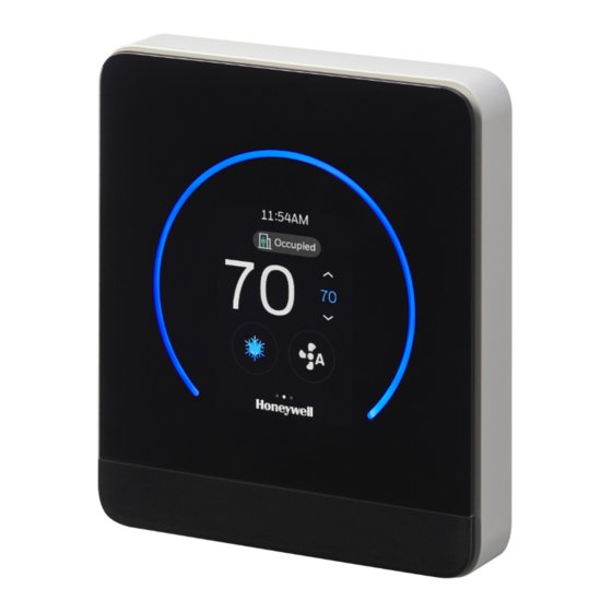
2 - OVERVIEW Home screen: Temperature reading and adjustment Table 13: Home screen (main screen) Overview Item Description Time Alarm status Adjust temperature: Touch the up arrow to increase the desired temperature. Desired temperature: Displays the desired temperature. Adjust temperature: Touch the down arrow to decrease the desired temperature. Fan Speed: Indicates current Fan speed for Fan Coil unit. -
Page 27: Quick Access Screen (Right Side Screen): Device Configuration
QUICK ACCESS SCREEN (RIGHT SIDE SCREEN): DEVICE CONFIGURATION Quick access screen (right side screen): Device configuration Swipe left from the home screen to view the Quick access screen. Table 14: Quick access screen Item Description The name assigned to the thermostat while performing initial set up. Override: Override unoccupied or standby modes to allow setpoint adjustments. -
Page 28: Ambiance Screen (Left Side Screen): Sensor Reading
2 - OVERVIEW Ambiance screen (left side screen): Sensor reading Swipe right from the home screen to view the Ambiance screen. Establish Internet connection with thermostat, setup the location or connect to outdoor sensors to display the humidity and outdoor temperature. See Initial Configuration Figure 3 Ambiance screen (left side screen) Note: The types of reading displayed varies according to the sensor connected to the... - Page 29 HOME SCREEN ICON OVERVIEW Table 16: Home Screen Icon Overview Icon Description Cooling mode Ventilation mode System off Fan auto Fan speed low Fan speed medium Fan speed high Fan circulate Occupied mode Standby mode Unoccupied mode Temporary mode Permanent mode Home screen icon overview...
-
Page 30: Inactive Display Modes
2 - OVERVIEW Active display modes Figure 4 Active display modes Inactive display modes Figure 5 Inactive display modes Note: To configure the ring LED and display, see Managing display settings Display timeout properties Table 17: Display timeout properties LCD back light LED back light LCD back light Time... -
Page 31: Display Timeout Properties
DISPLAY TIMEOUT PROPERTIES Table 17: Display timeout properties (Continued) LCD back light LED back light LCD back light Time Mode brightness brightness behavior (0-100, pwm) (0-100, pwm) Dimmer when no user In 10 Normal/Disable activity seconds LCD Off/Enable dark mode Off/black when no user In 30 Normal... - Page 32 2 - OVERVIEW Display timeout properties...
-
Page 33: Getting Started
CHAPTER Getting Started This chapter contains steps and descriptions to set up the initial configuration of the thermostat and other basic configurations. Related topics Prerequisites Boot-up the thermostat... -
Page 34: Prerequisites
3 - GETTING STARTED Prerequisites Before going through initial guided setup sequences, ensure the TC300 is installed and wired up according to the TC300 installation and mounting guide. WARNINGS • To reduce the risk of electrical shock do not open the thermostat. There are no user- serviceable parts inside. -
Page 35: Boot-Up The Thermostat
Configuring the Service Info To set up the thermostat 1. Boot-up the thermostat. The Honeywell logo screen appears, followed by the “Welcome to TC300” screen. Figure 4 Welcome screens The Welcome screen followed by the LET’S BEGIN screen appears. Boot-up the thermostat... - Page 36 3 - GETTING STARTED Figure 5 Welcome screen 2. Tap LET’s BEGIN. The Device Name appears. Assigning a name to the thermostat Figure 6 Device Name 3. Tap on the text field A keyboard will be displayed on the screen to enter the device name. 4.
- Page 37 BOOT-UP THE THERMOSTAT Connecting to network Figure 7 Connection 6. If no connection is required, tap SKIP or tap the right arrow button. If connection is required, the connection screen appears. Figure 8 Connection 7. Tap BACnet MS/TP and enable the MSTP connection. See Managing connection.
- Page 38 3 - GETTING STARTED Selecting a temperature unit Figure 9 Temperature unit 9. Select a preferred temperature unit. 10. Set the Date & Time. See Setting Date and Time Setting Date and Time Figure 10 Date and Time Configuration screen 11.
- Page 39 BOOT-UP THE THERMOSTAT Setting up the Equipment type The TC300 is designed to control Fan coil units. It can control 4 pipe dual coil, 4 pipe single coil, and 2 pipe single coil. Figure 11 Equipment and I/O 16. Tap Equipment and set the equipment details. See Equipment configuration.
- Page 40 3 - GETTING STARTED 19. Set the required parameters and tap the right arrow button. The Setpoints screen appears. Figure 13 Setpoints 20. Configure the Occupied, Standby, and Unoccupied setpoints. See After set up the thermostat device, you can re-configure the user management equipment, schedules, alarms, and terminal assignments.
- Page 41 BOOT-UP THE THERMOSTAT Configuration. Configuring the Service Info Figure 15 Service Info 25. Enter the service personnel information. 26. Tap the right arrow button. The Congratulations message appears. Figure 16 Successful connection 27. Tap DONE. The User Management screen appears. Boot-up the thermostat...
- Page 42 3 - GETTING STARTED Figure 17 User management 28. Tap YES to configure the user list. See 29. Tap No to start using the thermostat. Thermostat Home screen appears. Figure 18 Home screen After set up the thermostat device, you can re-configure the user management equipment, schedules, alarms, and terminal assignments.
-
Page 43: Configuration
CHAPTER Configuration This chapter contains thermostat level configuration and equipment level configuration procedures. Only the Installer has access to these configuration screens. Related topics Configuration screen Basic configuration Equipment configuration I/O terminal assignment Configuring sensors Managing System switch Managing Discharge air control Managing Dehumidification Managing Valve cycle Advanced configuration... -
Page 44: Configuration Screen
4 - CONFIGURATION Configuring Home screen (Display Management) Managing display settings Reset to default Viewing the system status Managing Setpoints Changing the system mode Changing the fan speed Configuration screen The configuration screen displays all the configuration items of the thermostat and equipment. -
Page 45: Basic Configuration
BASIC CONFIGURATION Basic configuration The Basic Configuration includes options to configure the thermostat setting such as Device Name, Date and Time, Screen Cleaning, Override Setting, and Service Info. You might have configured these configurations while setting up the thermostat. However, you can change the configuration here again. Figure 20 Basic configuration The following features are covered under the Basic configuration. - Page 46 4 - CONFIGURATION Figure 21 Naming the thermostat 3. Tap on the text field A keyboard will be displayed on the screen to enter the device name. 4. Enter the device name. Assign a unique name to a thermostat specifying a name to the location where the thermostat is installed.
- Page 47 BASIC CONFIGURATION 5. Enable Daylight Savings if required. 6. If Daylight saving is enabled, set the start and end date schedules for daylight savings. 7. Tap the back button to navigate back to the previous screen. To enable screen cleaning mode Screen cleaning mode lock/disable the touch sensitivity of the display for 30 seconds so you clean the device display while the thermostat is functional.
- Page 48 4 - CONFIGURATION Figure 24 Override setting 3. Tap Temporary Override to set the temporary overrides when the user override the setpoint. The temporary override is default. The Temporary override screen appears. Figure 25 Temporary override 4. Set the time limit that temporary override should last. After this time, setpoint return to the scheduled mode.
-
Page 49: Equipment Configuration
EQUIPMENT CONFIGURATION Figure 26 Service information 3. Update the name and phone number of the service personnel. 4. Tap the back button to navigate back to the previous screen and save the modified information. Equipment configuration The equipment tab provides options to configure the equipment and devices connected to the thermostat. - Page 50 4 - CONFIGURATION Figure 27 Equipment screen To configure equipment and I/O 1. Swipe left from the Home screen. 2. On the Quick access screen, tap > Equipment > Equipment & I/O. The Equipment screen appears. Figure 28 Equipment and I/O 3.
- Page 51 Figure 29 Equipment and I/O types To configure the type of the equipment TC300 thermostat provides options to control three equipment types such as 4-pipe dual coil, 4-pipe single coil, and 2-pipe single coil. Here, you configure the cooling valve, heating valve types, floating and modulating controls.
- Page 52 4 - CONFIGURATION 4-Pipe Dual Coil 1. Tap 4-Pipe Dual Coil. The 4-Pipe Dual Coil screen appears. Table 19: 4-Pipe dual coil Valve Valve type Options Description operation options Cooling Valve On/Off Normally closed Set Valve output type as N.C Normally Open Set Valve output type as N.O •...
- Page 53 EQUIPMENT CONFIGURATION 4-Pipe Single Coil 2. Tap 4-Pipe Single Coil. The 4-Pipe Single Coil screen appears. Table 20: 4-Pipe single coil Valve Valve type operation/ Options Description Output Regulating and changeover On/Off Normally open Set Valve output type as N.C Normally close Set Valve output type as N.O •...
- Page 54 4 - CONFIGURATION If Output is set to 2-10 Vdc - Heating Rage: 2.0-5.7 Vdc - Cooling Range: 6.3-10.0 Vdc - Off voltage is 6.0 Vdc 2-Pipe Single Coil 3. Tap 2-Pipe Single Coil. The 2-Pipe Single Coil screen appears. Table 21: 2-Pipe single coil Heating/Cooling type Controls...
- Page 55 EQUIPMENT CONFIGURATION Table 21: 2-Pipe single coil Heating/Cooling type Controls Options Description • Set Valve output type as N.C cool only On/Off Normally closed • Set Valve output type as N.O Normally open • Set output type Direct or Reverse Floating •...
- Page 56 4 - CONFIGURATION Figure 32 Sensors 3. Tap the required sensor, relevant sub menu appears to select the settings. Note: The desire option may be “grayed-out” whenever there are insufficient outputs to support this function. Verify I/O is configured appropriately. To configure Auxiliary heat 1.
-
Page 57: I/O Terminal Assignment
I/O TERMINAL ASSIGNMENT 3. Set the Peripheral and Supplemental values. Peripheral heat runs in conjunction with main fan heat cycle for improved comfort and is performed by external radiant or other heating resources. Supplemental heat is a form of staged heating that is only initiated when primary fan coil heat function cannot maintain heating setpoint. - Page 58 4 - CONFIGURATION Figure 35 Terminals • Based on selected equipment function the terminals will be pre-assigned. To override default terminal assignment select alternate(s) as required. • If a terminal is assigned incorrect, then there will be a red box around the terminal button. Reassign the terminal.
-
Page 59: Configuring Sensors
Configuring sensors Thermostat supports Sylk sensors and Control sensors (temperature and humidity only). In order to ensure proper operation and control, configure for Sylk devices only when using Honeywell compatible sensors. To configure sensors 1. Swipe left from the Home screen. - Page 60 4 - CONFIGURATION Figure 39 Sensors screen 4. Tap the required sensor, relevant sub menu appears to select the settings. Note: The desire option may be “grayed-out” whenever there are insufficient outputs to support this function. Verify I/O is configured appropriately. To configure Sylk sensors Make sure that the required Sylk devices are connected to the thermostat.
- Page 61 Note: The total number of Sylk Devices is restricted by Power and Communication bandwidth. In general, the number of Sylk devices cannot exceed the allowed limit. Contact the Honeywell Technical Support team for additional support. 3. Tap the right arrow in the menu option to view the dip switch bus address setting guide.
- Page 62 4 - CONFIGURATION Table 22: Sylk device dip switches Sylk Device Type Sensors DIP Switches Address Discharge Air C7400S Sensor 4. Turn on the sensors. To configure Sensor offset 1. Swipe left from the Home screen. 2. On the Quick access screen, tap >...
- Page 63 CONFIGURING SENSORS Figure 42 Offset screens for temperature and humidity Note: These offsets should be used only when measured temperature or humidity is verified with calibrated sensor located in same location. Configuring sensors...
-
Page 64: Managing System Switch
The thermostat groups the control sensors into three types. There are Local sensor, Remote sensor, and Multi sensor. Local Sensor: Internal TC300 temperature sensor. Installer can configure offsets to on-board temperature and humidity sensors, if desired. Remote Sensor: Space temperature sensor connected to UI/UIO terminal, or TR40 sensor configured at address 2. -
Page 65: Managing Discharge Air Control
3. Select a system switch that corresponds with the HVAC equipment. Commands from the network to control the system switch mode take precedence over the setting on the TC300. The system switch setting is saved during power outages. Managing Discharge air control The discharge air controller option is available only if the selected equipment type is Fan coil with the floating, modulating valve, or 6-way valves. - Page 66 4 - CONFIGURATION 2. On the Quick access screen, tap > Equipment > Discharge Air Control. The Discharge Air Control screen appears. 3. Enable the Discharge Air Control. Figure 45 Discharge air control 4. Tap Setpoints to set the Maximum Heating, Heating Initial Offset, Maximum Cooling, and Cooling Initial Offset.
-
Page 67: Managing Dehumidification
MANAGING DEHUMIDIFICATION Figure 47 On-screen help Managing Dehumidification Dehumidification function will maintain humidity below programmed setpoint using onboard humidity sensor. For systems without reheat the dehumidification function will allow cooling below the target setpoint based on programmed over cool offset. If humidity threshold cannot be achieved once lower space temperature threshold has been reached the dehumidification function will be suspended. -
Page 68: Managing Valve Cycle
4 - CONFIGURATION Figure 48 Dehumidification Note: The Reheat option is applicable only for 4-pipe dual coil. Aux Heat for Reheat is applicable for both 4- pipe single coil and 2-pipe single coil. 3. The dehumidification icon appears on Home screen. Managing Valve cycle Valve Cycle function is used to periodically cycle valve every 24 hours to minimize risk of sticking/binding. -
Page 69: Advanced Configuration
ADVANCED CONFIGURATION Figure 49 Valve cycle Advanced configuration The Advanced configuration screen displays all the advanced options of the thermostat. To view Advanced options 1. Swipe left from the Home screen. 2. On the Quick access screen, tap > Advanced. The Advanced configuration screen appears. -
Page 70: Managing Setpoint Options
4 - CONFIGURATION Figure 50 Advanced configuration Managing Setpoint options This option allows users to set the maximum or minimum temperature setpoints. To configure setpoint options 1. Swipe left from the Home screen. 2. On the Quick access screen, tap >... - Page 71 MANAGING SETPOINT OPTIONS Figure 51 Setpoint options Table 23: Setpoint options Operation Configuration Range Description Type Cooling Min. 50-99°F (Default The minimum cool setpoint that can be set Setpoint 50°F) by the user Stops Heating Max. 40-105°F (Default The maximum heat setpoint can be set by Setpoint 90°F) the user...
-
Page 72: Managing Cooling Options
4 - CONFIGURATION Table 23: Setpoint options Operation Configuration Range Description Type Cooling Setpoint Ramp 0 -20°F/hr (Default When outside air temperature is available, Recovery 6°F/hr the effective cool ramp rate is changed as the outdoor air temperature changes. When the outdoor air temperature is at the minimum cool ramp rate temperature (e.g. - Page 73 MANAGING COOLING OPTIONS Figure 52 Cooling options Table 24: Cooling options Cooling Configuration Range Description type Type DAT Limit DAT Cooling Low -40 to 60°F When the discharge air temperature is below the Limit (Default 45°F) discharge air low limit setpoint, the cooling control will turn off cooling physical output until the discharge air temperature rises above it's setpoint +2 °F differential.
-
Page 74: Managing Heating Options
4 - CONFIGURATION Managing Heating options To configure cooling options 1. Swipe left from the Home screen. 2. On the Quick access screen, tap > Advanced > Heating. The Heating Options screen appears. Figure 53 Heating options Table 25: Heating options Heating Configuration Range... -
Page 75: Managing Pipe Sensor Thresholds
MANAGING PIPE SENSOR THRESHOLDS Table 25: Heating options (Continued) Heating Configuration Range Description type Type Fan Delay Fan On Delay 0 to 30 Sec Fan on delay time after heating outputs are turned Time Default 30 on. May be used to run fan after heating outputs have turned on for some times so that heating coil can warm up. -
Page 76: Managing Valve Purge
4 - CONFIGURATION Table 26: Pipe sensor threshold (Continued) Operation Configuration Range Description Type Temp Offset (Heat) 5 to 10°F (Default When the pipe temperature is above the 5°F) space temperature and the hybrid control is enabled, than the offset is suitable for heating. -
Page 77: Miscellaneous
MISCELLANEOUS Miscellaneous To configure miscellaneous 1. Swipe left from the Home screen. > Advanced > Miscellaneous. 2. On the Quick access screen, tap The Miscellaneous screen appears. Figure 56 Miscellaneous 3. Power Up Delay Time - The thermostat will perform a delayed after controller power up. User can set 0 to 300 Sec delay. - Page 78 4 - CONFIGURATION Figure 57 Service mode enabling Based on terminal configuration, the following screen displays different options for manual testing. For example, in below screen, single speed fan, Heating equipments, Cooling floating, and Aux heat equipments are configured. Connect these test equipment to the relevant terminals and test for actual output.
-
Page 79: Managing Standby Action
MANAGING STANDBY ACTION Figure 59 Typical service mode options 5. To exit the service mode, on the service mode screen, tap the back arrow button. A confirmation message appears. Figure 60 Service mode exit 6. Tap YES. The service mode will exit and thermostat resume normal function. Managing Standby action The Standby Action refers to which mode setpoints to be used while the thermostat is in Standby mode. -
Page 80: Viewing The Security Log
4 - CONFIGURATION 2. On the Quick access screen, tap > Advanced > Standby Action. The Standby Action screen appears. Figure 61 Standby action 3. Tap Treat as Occupied or Treat as Unoccupied. Viewing the Security log The security log contains records of the critical security events such as password change, user role switch, firmware upgrade and so on. -
Page 81: Managing Connection
5. Application Info - Application info shows DDC runtime. 6. Thermal Info - Thermal information of the connected devices. Managing connection TC300 supports BACnet MS/TP connection and Modbus connection. Either BACnet MS/TP or Modbus connection can be enabled at a time. To connect thermostat via BACnet MS/TP 1. - Page 82 5. The device automatically adapts to the baud rate of the MS/TP network. You can also manually select the Baudrate 6. Enter a unique Device ID for the thermostat. It should be different from other TC300 thermostats. 7. Auto-MAC addressing is enabled by default, Installer can also manually set a unique MAC address for the TC300.
- Page 83 MANAGING CONNECTION Figure 67 Baud Rate 10. Tap the back arrow button to navigate back to BACnet MS/TP setting screen. 11. Tap BACnet MS/TP Setting. The BACnet MS/TP setting screen appears. Figure 68 BACnet MS/TP Setting Managing connection...
- Page 84 12. Set the desired parameters and tap the back arrow button to navigate back to the connection screen. TC300 will try to adapt to the Baudrate of the MS/TP network in the first 4 minutes after startup or MS/TP is enabled. If no Baudrate could be determined, for example, there is a single device on the network, then TC300 will choose the default Baudrate of 76800.
-
Page 85: User Management
USER MANAGEMENT User management The TC300 supports four kinds of user identities as identified in Table with limited privileges as noted. Except for the Installer role these privileges can be reduced in the user settings menu. Table 27: User roles and permissions... - Page 86 4 - CONFIGURATION Figure 70 User management Visitor To view the Visitor user role 1. On the User Management screen, select Visitor. 2. Tap to go to the previous screen. Basic user To manage the Basic User role 1. On the User Management screen, select Basic User, and tap The Basic User screen appears.
- Page 87 CONFIGURING THE USER ROLES Figure 72 Basic user permission. 4. Toggle the undesired Permissions to “Off” position. Admin To manage the Admin role 1. On the User Management screen, select Admin, and tap The Admin User screen appears. 2. Set a passcode and user permission. The passcode will be used by the Admin user to access the thermostat.
-
Page 88: Configuring Home Screen (Display Management)
4 - CONFIGURATION Figure 74 Admin user permission. 4. Toggle the undesired Permissions to “Off” position. Installer To manage the Installer role 1. On the User Management screen, select Installer, and tap 2. Set or change a Passcode. Refer to Passcode rules. -
Page 89: Managing Display Settings
MANAGING DISPLAY SETTINGS Figure 76 Display management All icons are enabled by default. You can turn it off by sliding the toggle button to the left. 3. Tap Branding to select a brand name that will be displayed on the home screen. 4. - Page 90 4 - CONFIGURATION 2. On the Quick access screen, tap The Display Settings screen appears. Figure 78 Display settings 3. Tap Brightness. The Brightness screen appears. Figure 79 Brightness 4. Tap Display and move the slider to right to increase the brightness of the display. 5.
-
Page 91: Reset To Default
RESET TO DEFAULT Figure 80 Inactive display 8. Tap Display Off to set the display off. However, the ring LED breaths to show the system mode. Or, tap Always On to show both display and ring LED. Or, tap Always Off to keep both ring LED and display off. -
Page 92: Viewing The System Status
4 - CONFIGURATION Figure 82 Weekly reset and confirmation message 6. Upon successful reset, user will be notified by a notification banner. Viewing the system status The system status shows device information, live status and readings of the sensors that are operated or connected with the thermostat. These values are view only. To view system status 1. -
Page 93: Managing Setpoints
MANAGING SETPOINTS Figure 84 System status Table 28: System status Operating status Equipment type, Current operating mode, Heat status, Cool status, Aux heat, Fan status, Indoor temperature, Indoor setpoint, Indoor humidity, Indoor CO2, Discharge air temperature, Discharge air control setpoint, Pipe temperature, Recovery status, Override remaining, Run time, Restart reason, Terminal load, UTC offset Schedule... - Page 94 4 - CONFIGURATION Figure 85 Quick access screen 2. On the Quick access screen, tap The Setpoint screen appears. Figure 86 Define the setpoints 3. On the Setpoint screen, tap Occupied, Standby, or Unoccupied The Occupied screen appears. Figure 87 Occupied Tip: Long press the +/- button to quickly increase or decrease the value.
-
Page 95: Changing The System Mode
CHANGING THE SYSTEM MODE 4. Configure the required setpoint limits for Occupied, Standby, and Unoccupied modes. Thermostat performs limit checking on all temperature setpoints, in case setpoint relationships are violated. • Occupied mode treats the building space as occupied and configured with comfort setpoints. -
Page 96: Changing The Fan Speed
4 - CONFIGURATION Changing the fan speed To change the fan speed 1. On the Home screen, tap mode icon, for example The Fan Speed screen appears. Figure 89 Fan speed 2. Select a fan speed and tap the back arrow button. The fan speed is changed. -
Page 97: Alarms
Managing the alarms Alarms In the TC300 thermostat, alarms are configured for predefined set values. When the values are breached, the alarms are triggered and displayed on the home screen as banner notification, dot notification, and on the Alarm button. You can view the triggered alarms and acknowledge them. -
Page 98: Alarm Notification
5 - ALARMS Alarm notification The alarms can be configured as banner notification or dot notification as per the alarm configuration. The banner notification is pop-up on the home screen whereas the dot notification appears beside the time. For alarm configuration, refer to Configuring the alarm preference Figure 91 Alarm banner notification You can tap the banner notification to view the alarm and acknowledge it. - Page 99 ALARM PREFERENCE Figure 93 Alarm types 4. Tap an alarm type, for example, Proof of air flow alarm. The configuration screen of the alarm type appears. Alarm preference...
- Page 100 5 - ALARMS Figure 94 Alarm configuration screen Alarm reason description is displayed on the screen. 5. Toggle the Allow Banner Notification to on to get the banner notification of the this type of alarm on the home screen. Note: Dot notification of alarm is default. The dot will appear on Alarm bell icon on the home screen and Configuration screen.
-
Page 101: Unacknowledged Alarms
UNACKNOWLEDGED ALARMS 4. Tap Pipe Temperature Limits to set the limits for pipe temperature, when its break, alarm will be raised. Figure 96 Alarm limits Unacknowledged alarms In addition to the banner notification, all other alarms (for which the notification is not configured) can be viewed and acknowledged under the Alarm screen. - Page 102 5 - ALARMS Figure 98 Alarm preference - Alarm 3. Tap Alarm. A list of unacknowledged alarms appears. Figure 99 Unacknowledged alarms 4. Tap an Alarm name. The corresponding alarm property screen appears. The alarm property screen describes the nature of event state transition. Unacknowledged alarms...
-
Page 103: List Of Alarms And Their Severity
LIST OF ALARMS AND THEIR SEVERITY Figure 100 Alarm detail 5. Tap CONFIRM. The Alarm Detail screen appears. Figure 101 Alarm detail 6. Tap SERVICE to see the service phone number. List of alarms and their severity The list of alarms in the Commercial Connected thermostat is as follows Alarms Severity Proof of Air Flow Alarm... - Page 104 5 - ALARMS Alarms Severity Pipe Sensor Out of Range High Water Temperature is Not Suitable for Heating/Cooling High Room Temperature Changing Trend is Reversed with System Mode High Unknown Time Medium List of alarms and their severity...
-
Page 105: Managing The Alarms
MANAGING THE ALARMS Managing the alarms S.N0 Alarm Trigger Scenario Action Level Proof of Air Flow An input (e.g., a current switch or Depending on the alarm High Alarm (fan differential pressure switch) should be configuration: state) available to monitor proof of air flow in 1. - Page 106 5 - ALARMS S.N0 Alarm Trigger Scenario Action Level Space 1. Local Space temp as the main 1. If the sensor is utilized for the High Temperature control and sensor fault is detected. control loop and network input of (Action 2)/ Sensor Failure 2.
- Page 107 MANAGING THE ALARMS S.N0 Alarm Trigger Scenario Action Level Applicable only for Dual-Pipe FCU The heating/cooling valve will be High Water temperature is Heating/Cooling Systems. closed, and the fan will run based on not suitable for 1. Based on the Pipe Sensor transition the fan speed configuration.
- Page 108 5 - ALARMS Managing the alarms...
-
Page 109: Scheduling
Scheduling About Schedule TC300 enables you to plan operations based on the time of day and holidays. This scheduling structure allows you to control day-to-day operations with the standard schedule. The holiday schedule controls days or times when a facility is typically unoccupied. -
Page 110: Setting Up A Weekly Schedule
6 - SCHEDULING • Special event: Use Special event to create up to 10 special events. Note: Holiday schedules automatically write a 12:00 AM OFF time, which is in effect unless it is overridden by an event schedule. Related topics Setting up a weekly schedule Setting up a holiday schedule Special event... - Page 111 SETTING UP A WEEKLY SCHEDULE 3. Tap Weekly to add a new schedule. The Weekly screen appears. Figure 104 Weekly schedule screen 4. Select a day when to apply the weekly schedule. 5. Tap Add new event The Create screen appears. It displays two event types for scheduling.
- Page 112 6 - SCHEDULING 8. Tap an event type (Occupied or Standby). 9. Tap SAVE. The Weekly screen appears. It displays the created schedule under Monday. You can copy the schedule to other days. Refer to Copying the schedules from one day to another.
- Page 113 SETTING UP A WEEKLY SCHEDULE Editing or deleting weekly schedules The existing weekly schedules can be edited from the Weekly schedule screen. To change or delete an existing weekly schedule 1. On the Weekly schedule screen, tap the schedule to be modified. The Edit screen will appear.
- Page 114 6 - SCHEDULING Copying the schedules from one day to another The TC300 enables the user to copy an existing regular schedule. To copy a schedule from one day to another 1. Navigate to the Weekly schedule screen from where the schedule is to be copied.
-
Page 115: Setting Up A Holiday Schedule
SETTING UP A HOLIDAY SCHEDULE Figure 111 Copy successful Setting up a holiday schedule Holidays are defined as reoccurring events that are different from the weekly schedule, can be Occupied or Standby, or by default Unoccupied. So the Unoccupied/Standby mode setpoints will be executed on the holidays. There are two holiday types are available to choose. - Page 116 6 - SCHEDULING Figure 113 Schedule types 3. Tap Holiday to add a new holiday schedule. The Holiday screen appears. Figure 114 Holiday screen 4. Tap the add button to add a Holiday. The Create Holiday screen appears. Figure 115 Creating Holiday 5.
- Page 117 SETTING UP A HOLIDAY SCHEDULE Figure 116 Set Date 6. Tap Floating Date to schedule a floating date as a holiday (Organization related holidays) or tap Specific Date to schedule festival holidays, government holidays, or public holidays. If Floating date is selected, then you can choose only one day to create an event. 7.
- Page 118 6 - SCHEDULING Figure 118 Create holiday vent screen 14. Tap the Start clock icon to set the event start time. 15. Set the start time and then tap CONFIRM. 16. Tap the End clock icon. 17. Set the event end time and then tap CONFIRM. 18.
- Page 119 SETTING UP A HOLIDAY SCHEDULE Editing or deleting Holiday The existing weekly Holidays can be edited from the Holiday screen. To change or delete an existing holiday 1. On the Holiday screen, tap the schedule to be modified. The Edit screen will appear. Figure 119 Editing a regular Holiday 2.
- Page 120 6 - SCHEDULING Copying the Holiday events from one day to another The TC300 enables the user to copy an existing holidays. To copy a schedule from one day to another 1. Navigate to the Holiday screen from where the holiday is to be copied.
-
Page 121: Special Event
SPECIAL EVENT Figure 122 Copy successful Special event Special events are one time events that are different from the weekly schedule. To create a special event 1. Right swipe the home screen. 2. On the Quick access screen, tap Schedule and then tap Special Event. The Special Event screen appears. - Page 122 6 - SCHEDULING Figure 124 Create special event 4. Tap Date. The Set Date screen appears. Figure 125 Set date screen 5. Select a date. Note: The thermostat supports special event configuration only for three years from the current date. If the special event reoccurs on multiple days, then increase the holiday count.
- Page 123 SPECIAL EVENT Figure 126 Adding new event 8. Tap Add new event. The Create Event screen appears. 9. Tap the clock icon for Start. 10. Set the special event start time and then tap CONFIRM. 11. Tap the clock for End. 12.
- Page 124 6 - SCHEDULING Special event...