Table of Contents
Advertisement
Quick Links
GE Healthcare
CARESCAPE
Service Manual
V100 Vital Signs Monitor
™
S ys tolic
Silence
Alarms
Dias tolic
Puls e R ate
INFLATE PRESSURE
Menu
ALARM VOLUME
PULSE VOLUME
S pO
HIGH
LOW
HIGH
Inflate/Stop
MAP/Cuff
ADULT
LOW
NEONATE
Cycle
AUTO CYCLE
HIGH
HISTORY
History
LOW
To clear hold
2 seconds
BATTERY OK
Print
HIGH
BATTERY LOW
CHARGING
LOW
Temperature
On / Off
C
F
CARESCAPE V100 Vital Signs Monitor
English
2037107-002 (CD)
2048724-002 (paper)
© 2010, 2011 General Electric Company.
All rights reserved.
Advertisement
Table of Contents

Related Manuals for GE CareScape V100


Summary of Contents for GE CareScape V100
- Page 1 Puls e R ate INFLATE PRESSURE Menu HIGH BATTERY LOW ALARM VOLUME PULSE VOLUME CHARGING S pO Temperature On / Off HIGH CARESCAPE V100 Vital Signs Monitor English 2037107-002 (CD) 2048724-002 (paper) © 2010, 2011 General Electric Company. All rights reserved.
- Page 2 NOTE: The information in this manual applies to CARESCAPE V100 Vital Signs Monitor software version R1.5. Due to continuing product innovation, specifications in this manual are subject to change without notice. NOTE: For technical documentation purposes, the abbreviation GE is used for the legal entity name, GE Medical Systems Information Technologies, Inc.
-
Page 3: Table Of Contents
Monitor ............1-16 2048723-002C CARESCAPE V100 Vital Signs Monitor... - Page 4 Host communication port ......... .2-6 CARESCAPE V100 vital signs monitor connectivity options ..2-6 Product compliance .
- Page 5 Exergen ........... . . 4-12 Ohmeda, Nellcor, and Masimo SpO2 technologies ....4-12 2048723-002C CARESCAPE V100 Vital Signs Monitor...
- Page 6 Exergen-specific error codes ........5-7 CARESCAPE V100 Vital Signs Monitor...
- Page 7 NIBP ............. . A-4 2048723-002C CARESCAPE V100 Vital Signs Monitor...
- Page 8 Summary ............B-4 Electromagnetic compatibility (EMC) C-1 Electromagnetic compatibility (EMC): CARESCAPE V100 monitor ..C-1 Guidance and manufacturer’s declaration – electromagnetic emissions .
-
Page 9: Introduction
Introduction 2048723-002C CARESCAPE V100 Vital Signs Monitor... -
Page 10: Revision History
Ordering manuals A paper copy of this manual will be provided upon request. Contact your local GE representative and request the part number on the first page of the manual. CARESCAPE V100 Vital Signs Monitor... -
Page 11: Conventions Used In This Manual
For technical documentation purposes, the abbreviation GE is used for the legal entity names, GE Medical Systems Information Technologies, Inc. In this manual, the CARESCAPE V100 vital signs monitor is referred to as the monitor. Names of hardware keys on the equipment are written in bold typeface: ... -
Page 12: Safety Information
Caution, and Note are used throughout the manual. In addition, standard equipment symbols are defined. Responsibility of the manufacturer GE is responsible for the effects on safety, reliability, and performance only if: assembly operations, extensions, readjustments, modifications, or repairs ... -
Page 13: Dangers, Warnings, Cautions, And Notes
Do not perform any testing or maintenance on a sensor while it is being used to monitor a patient. WARNING Place the monitor on a rigid, secure surface or use the monitor with mounting hardware, poles, and stands recommended by 2048723-002C CARESCAPE V100 Vital Signs Monitor... - Page 14 Arrange the external AC/DC power converter, air hoses, and all cables carefully so they do not constitute a hazard. WARNING If powering the monitor from an external power adapter or converter, use only GE-approved power adapters and converters. WARNING The speaker is tested during unit power-up. If the power-up tones are not heard, audible alarms will also not be heard.
- Page 15 WARNING Do not use any battery other than a GE-recommended battery. Other batteries may not provide the same operating time and may cause unexpected monitor shutdown. Other batteries may be incompatible with the internal charger and may cause battery acid leakage, fire, or explosion.
- Page 16 The equipment or system should not be used adjacent to, or stacked with, other equipment. If adjacent or stacked use is necessary, the equipment or system should be tested to verify normal operation in the configuration in which it is being used. CARESCAPE V100 Vital Signs Monitor 2048723-002C...
- Page 17 The monitor does not include any user-replaceable fuses. Refer servicing to qualified service personnel. CAUTION Do not use replacement batteries other than the type supplied with the monitor. Use only batteries recommended by GE. Other batteries could result in monitor shutdown. Replacement batteries are available from GE. CAUTION...
-
Page 18: Equipment Symbols
For detailed information, refer to the Electromagnetic compatibility (EMC) appendix in this manual. Equipment symbols The following symbols are associated with the CARESCAPE V100 vital signs monitor. NOTE The model of the monitor determines which symbols appear on it. - Page 19 Manufacturer: This symbol is accompanied by the name and the address of the manufacturer. Manufacturing Date: This symbol is accompanied by the date of the manufacturing. 2048723-002C CARESCAPE V100 Vital Signs Monitor 1-11...
- Page 20 (WEEE): This symbol indicates that the waste of electrical and electronic equipment must not be disposed as unsorted municipal waste and must be collected separately. Please contact an authorized representative of the manufacturer for information concerning the decommissioning of your equipment 1-12 CARESCAPE V100 Vital Signs Monitor 2048723-002C...
-
Page 21: Service Requirements
Any unauthorized attempt to repair equipment under warranty voids that warranty. It is the user’s responsibility to report the need for service to GE or to one of GE’s authorized agents. Failure on the part of the responsible individual, hospital or institution using ... -
Page 22: Related Manuals
If you are unable to resolve the problem after checking these items, contact GE. Prior to calling, please be prepared to provide: product name, model number, and serial number ... -
Page 23: Packing Instructions
As you use the monitor, you will accumulate solid wastes that require proper disposal or recycling. These include batteries, patient applied parts, and packaging material. Dispose of these materials according to local or national regulations. 2048723-002C CARESCAPE V100 Vital Signs Monitor 1-15... -
Page 24: Batteries
At the end of its service life, the product described in this manual, as well as its accessories, must be disposed of in compliance with the guidelines regulating the disposal of such products. If you have questions concerning disposal of the product, please contact GE or its representatives. 1-16 CARESCAPE V100 Vital Signs Monitor... -
Page 25: Equipment Overview
Equipment overview 2048723-002C CARESCAPE V100 Vital Signs Monitor... -
Page 26: Equipment Description
Each CARESCAPE V100 vital signs monitor is supplied with an accessory pack. The contents of the pack vary according to model. Unpack the items carefully. If an accessory is missing or if an item is in a nonworking condition, contact GE Customer Service immediately. -
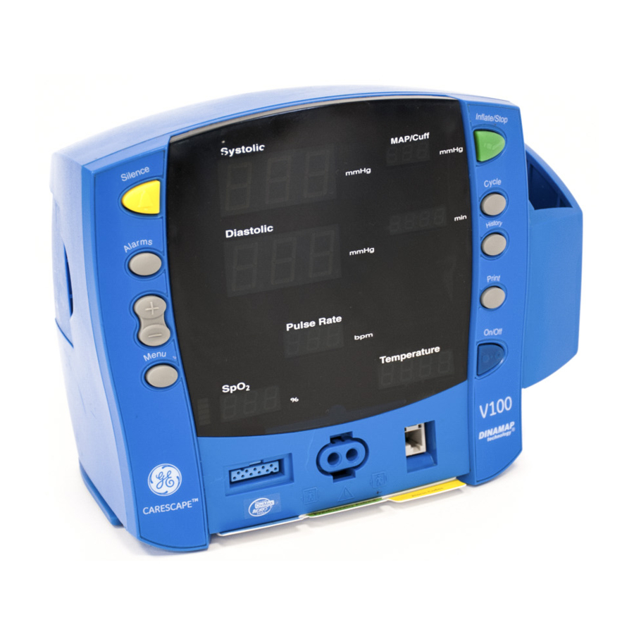
Page 27: Front Controls And Connectors
ADULT indicator encompasses both adult and pediatric patients. sensor connector: attach SpO cables here. NIBP connector: attach NIBP cuff hoses here. Inflate/Stop button: starts a manual NIBP determination or stop any NIBP determination. Temperature probe holster: stores Alaris temperature probe. 2048723-002C CARESCAPE V100 Vital Signs Monitor... -
Page 28: Front Panel Indicators
Adjustable for adult/ped and neonate patients. 19. ALARM VOLUME indicator: flashes to indicate you are making a change to the alarm volume. 20. PULSE VOLUME indicator: flashes to indicate you are making a change to the pulse volume. CARESCAPE V100 Vital Signs Monitor 2048723-002C... -
Page 29: Right-Side Panel
(less than 45 minutes when solid; 5 minutes or less when flashing). 32. CHARGING indicator: lights green to indicate presence of external power source and battery charging. 33. Temperature window: indicates measured temperature. Right-side panel 2048723-002C CARESCAPE V100 Vital Signs Monitor... -
Page 30: Rear Panel
Printer door. Host communication port The host communication port is used to interface the CARESCAPE V100 vital signs monitor with other electronic devices (a central nurse's station or remote alarm device), or with the Exergen scanner. For further information, reference the Host Communication manual. -
Page 31: Product Compliance
GE sales representative for the latest information on connectivity solutions for your monitor. Product compliance The CARESCAPE V100 vital signs monitor is classified in the following categories for compliance with IEC 60601-1: Internally powered or Class II when powered from external supply. -
Page 32: Spo2
When the cuff and hose are attached to the monitor and a Non-Invasive Blood Pressure (NIBP) determination is initiated, the pump inflates the cuff. Pressure transducers PT1 and PT2 monitor pressure information. The pneumatic manifold CARESCAPE V100 Vital Signs Monitor 2048723-002C... -
Page 33: Dinamap Superstat Algorithm
The figure shows a full determination sequence for an adult patient. In Stat mode, some steps may require only one pulse. 2048723-002C CARESCAPE V100 Vital Signs Monitor... - Page 34 The algorithm will inflate above the initial target pressure to obtain more data in the systolic region. The pressure is limited to the maximum allowed for the selected patient type. 2-10 CARESCAPE V100 Vital Signs Monitor 2048723-002C...
-
Page 35: Dinamap Classic And Auscultatory Reference Algorithm
At each step the microprocessor stores cuff pressure, the matched pulse amplitude, and the time between successive pulses. The stepped deflation and matched pulse detection continues until diastolic pressure is determined or total 2048723-002C CARESCAPE V100 Vital Signs Monitor 2-11... -
Page 36: Reference Used To Determine Nibp Accuracy
For neonatal mode, the reference is always the intra-arterial pressure monitoring method. Monitors with intra-arterial reference (DINAMAP SuperSTAT and classic technology) For these monitors, the NIBP is referenced to the invasive blood pressure obtained at the central aortic region. 2-12 CARESCAPE V100 Vital Signs Monitor 2048723-002C... -
Page 37: Temperature
The Turbo Temp or Tri-Site temperature options support two different temperature measurement modes of operation: fast (predictive) or continuous (monitor). The Turbo Temp temperature option can take a fast (predictive) oral or rectal 2048723-002C CARESCAPE V100 Vital Signs Monitor 2-13... -
Page 38: Exergen Temperature
The Power processor is powered at all times. The NIBP processor controls pneumatic safety interlock, timing check, and NIBP control. The temperature processor controls the temperature parameter. 2-14 CARESCAPE V100 Vital Signs Monitor 2048723-002C... -
Page 39: User Interface (Ui) Board Pwa
PWA. The information is sent to the Main Board via the optically coupled electrically isolated serial connection. The primary processor receives the data and routes it to the UI board for display. The data is also sent to the printer if specified. 2048723-002C CARESCAPE V100 Vital Signs Monitor 2-15... -
Page 40: Printer
Optical switch The optical switch indicates whether the Alaris temperature probe is inserted in the probe holder or not. The Main Board powers the switch. 2-16 CARESCAPE V100 Vital Signs Monitor 2048723-002C... - Page 41 Equipment overview: Functional description 2048723-002C CARESCAPE V100 Vital Signs Monitor 2-17...
- Page 42 Equipment overview: Functional description For your notes 2-18 CARESCAPE V100 Vital Signs Monitor 2048723-002C...
-
Page 43: Installation
Installation 2048723-002C CARESCAPE V100 Vital Signs Monitor... -
Page 44: Unpacking And Preparation For Installation
DC output into the side of the monitor. NOTE Use only the original cord, a power cord recommended by GE, or a regulatory-approved cord for the country of use. Plug the AC cord into a Hospital Grounded AC receptacle. The word CHARGING will illuminate green on the front of the monitor indicating that an AC source is available. -
Page 45: Battery Ok
The BATTERY LOW alarm will re-alarm every 10 minutes after it has been acknowledged. If the alarm is not acknowledged, the alarm is re-issued every 8 seconds. The monitor continues to operate normally. 2048723-002C CARESCAPE V100 Vital Signs Monitor... -
Page 46: When About 5 Minutes Of Main Battery Charge Remains
The BATTERY LOW indicator flashes. This alarm can be acknowledged by pressing the Silence button. The user is not able to initiate: any new NIBP determinations of any type any printouts CARESCAPE V100 Vital Signs Monitor 2048723-002C... -
Page 47: Configuring The Monitor
Temperature window as follows: trb0 if the monitor is configured for Alaris Turbo Temp trI if the monitor is configured for Alaris Tri-Site tat if the monitor is configured for Exergen 2048723-002C CARESCAPE V100 Vital Signs Monitor... - Page 48 User selects the SMART Sat tolerance level * (Nellcor only) mode 4, 6, 8, 10, 12, 14, 16 User selects the number of seconds over which data is (Masimo only) averaged 4 to 16* CARESCAPE V100 Vital Signs Monitor 2048723-002C...
- Page 49 To exit the configuration mode, press the On/Off button. To continue with other changes, press the Menu button. will appear in the Systolic window. To change parameter settings, press the Menu button 2048723-002C CARESCAPE V100 Vital Signs Monitor...
- Page 50 Ohmeda TruSignal SpO Line Frequency mode (LF) will go back to default values. Refer to “Configuration mode settings” on page 3-5 to configure the factory default user settings. CARESCAPE V100 Vital Signs Monitor 2048723-002C...
- Page 51 Press the Menu button until n0d (averaging time) appears in the Pulse Rate window. Use the +/- buttons to select the option. Press the Menu button once. SAt (FastSAT) appears in the Pulse Rate window. Use the +/- buttons to select the option. 2048723-002C CARESCAPE V100 Vital Signs Monitor...
- Page 52 (°C or °F): Unplug the scanner from the monitor’s host communication port. On the back of the scanner, loosen the single screw at the bottom and remove the cover. Cover Single screw 3-10 CARESCAPE V100 Vital Signs Monitor 2048723-002C...
-
Page 53: Advanced Configuration Mode
After a moment, this version information is cleared, and the monitor displays the first page of configuration mode which simply displays ACF in the Systolic display window indicating that the monitor is in advanced configuration mode. 2048723-002C CARESCAPE V100 Vital Signs Monitor 3-11... -
Page 54: Service Mode
“Save Settings” operation is executed (on the final Service Mode options page). To save settings in service mode, advance to the last page (page 6), then press and hold the Menu button until the second of two tones sound. 3-12 CARESCAPE V100 Vital Signs Monitor 2048723-002C... - Page 55 4 (in min window) Type loaded (Displayed in SpO2% display window) 0: No SpO 1: Nellcor 2: Masimo 3: Ohmeda NOTE Incorrect setting will cause fatal 930 alarm during operation. 2048723-002C CARESCAPE V100 Vital Signs Monitor 3-13...
- Page 56 Greek Hungarian Italian Japanese Korean Norwegian Polish Not used Portuguese Russian Slovak Spanish Swedish NOTE You must be in option page 6 (in min window) to save any changes made in service mode. 3-14 CARESCAPE V100 Vital Signs Monitor 2048723-002C...
-
Page 57: Host Communication Connector
Host Comm Cable Assemblies (GE part numbers 683235 and 683242). USB Cable Kit (GE part number 2040229-001). If external alarm control is required, the Isolated Remote Alarm Cable (GE part number 487208CR) should always be used. When a high-priority alarm condition is displayed on the monitor, the remote alarm signal becomes active within 0.5 seconds. -
Page 58: Db15 Connector Pin Assignments
No connection No connection Communication protocol GE offers resources to assist customers in the development of software to exchange data with the monitor, including the Host Communications Reference Manual and the DINAWIN Application Programming Interface library. Contact your GE sales representative for further information. -
Page 59: Maintenance
Maintenance 2048723-002C CARESCAPE V100 Vital Signs Monitor... -
Page 60: Preventative Maintenance
NOTE GE does not, in any manner, assume the responsibility for performing the recommended maintenance schedule, unless an Equipment Maintenance Agreement exists. The sole responsibility rests with the individuals, hospitals, or institutions utilizing the device. -
Page 61: Visual Inspection
Do not let fluid “pool” around connection pins. WARNING Use of unapproved cleaning agents can cause case damage resulting in unintended fluid ingress and a potential for compromising electrical safety. 2048723-002C CARESCAPE V100 Vital Signs Monitor... -
Page 62: Scanner
Do not use bleach or other cleaning solutions on the sensor lens. Cleaning the probe head and neck of the Exergen temporal scanner Use an alcohol-based cleaning agent on the Exergen scanner’s probe head and metal neck only. CARESCAPE V100 Vital Signs Monitor 2048723-002C... -
Page 63: Cleaning And Disinfecting Blood Pressure Cuffs
Wipe away any excess solution and rinse the cuff again with distilled water. Allow 2 hours for drying. The user has the responsibility to validate any deviations from the recommended method of cleaning and disinfection. For additional information on infection control procedures, contact GE Technical Support. 2048723-002C CARESCAPE V100 Vital Signs Monitor... -
Page 64: Cleaning The Exterior Surfaces Of The Alaris Temperature Devices
If you question the effect your specific cleaning agent or disinfectant has on your instrument, contact your local GE Healthcare sales and service office or distributor. Do not use alcohol, ammonia, or ammonium chloride-based agents, as they could damage the plastic exterior of the probe. -
Page 65: Battery Care
It is best to keep the battery charged as fully as practical and never store the monitor with the battery in a discharged condition. When the battery will no longer hold a charge, remove the battery and replace it with a GE-approved battery. Failure to use a GE-approved battery may cause the monitor to shut down. - Page 66 battery. When the battery is replaced, all user settings are lost and return to default values. Replacement batteries can be obtained from GE. Unplug the monitor from the DC power source. Looking at the bottom of the monitor, remove the battery compartment cover by removing the four screws that secure the cover and help card tray.
-
Page 67: Exergen Temporal Scanner Battery
Replacing the Exergen temporal scanner battery Disconnect the scanner cable from the monitor. Loosen the two thumbscrews from the scanner’s modular plug. Unplug the scanner cable from the monitor’s host communication port. 2048723-002C CARESCAPE V100 Vital Signs Monitor... -
Page 68: Fuses
DC input, the main battery, and the remote alarm output. The +5 V output on the host port connector is regulated by internal supply. Fuses are not replaceable. 4-10 CARESCAPE V100 Vital Signs Monitor 2048723-002C... -
Page 69: Parameter Level Functional Testing
Take an oral or axillary temperature reading on yourself (i.e., not on a resistor simulator). Verify that a predictive temperature begins once the probe is removed from its holster. Place the probe in the holster after completion of the Temp cycle. 2048723-002C CARESCAPE V100 Vital Signs Monitor 4-11... -
Page 70: Exergen
Connect the cables prior to attaching to the monitor. Verify that an SpO reading is displayed within moments of attaching the sensor to either a simulator or to your finger. 4-12 CARESCAPE V100 Vital Signs Monitor 2048723-002C... -
Page 71: Calibration Procedures And Tests
Stopwatch/timer (capable of measuring seconds) Adult NIBP cuff, Neonate NIBP cuff, hose, inflation bulb, and associated tubing Calibration kit (p/n 320246, available through GE) cable (for appropriate SpO type, if SpO is installed) TE 1811 Temperature Probe Simulator (if TEMP is installed) available from ... -
Page 72: Setup
Allow the system to stabilize for 5 seconds (it is normal to see some decrease in pressure at this point). Start the stopwatch and record the pressure value. After 60 seconds record the pressure value. 4-14 CARESCAPE V100 Vital Signs Monitor 2048723-002C... -
Page 73: Pressure Transducer Verification
15. Record and verify the pressure reading that appears in the Systolic window. 16. Record and verify the pressure reading that appears in the Diastolic window. 17. Confirm all test results are recorded on the “Test results form” on page 4-29. 2048723-002C CARESCAPE V100 Vital Signs Monitor 4-15... -
Page 74: Pressure Transducer Calibration
Use the inflation bulb to inflate close to 150 mmHg. Slowly inflate (1 to 2 mmHg/sec) until valve opens and pressure is released. Record and verify pressure at which valve opens on the “Test results form” on page 4-29. Turn unit off. 4-16 CARESCAPE V100 Vital Signs Monitor 2048723-002C... -
Page 75: Button Testing
Press Inflate/Stop to begin NIBP determination. Verify ‘E80’ is displayed on the Systolic window and audible alarm sounds. Remove the air restriction. Press Inflate/Stop and verify that the pump does not start. Press the Silence button. 2048723-002C CARESCAPE V100 Vital Signs Monitor 4-17... -
Page 76: Led Tests
Confirm all test results are recorded on the “Test results form” on page 4-29. Temperature (perform if equipped with Temp module) At installation, GE recommends performing a temperature check. Refer to “Parameter level functional testing” “Temperature” on page 4-11. 4-18... -
Page 77: Alaris Temperature Calibration Verification
3-10 for instructions. 13. Confirm all test results are recorded on the “Test results form” on page 4-29. 14. Calibration is complete. If the monitor does not pass the calibration verification, contact GE Technical Support. 2048723-002C CARESCAPE V100 Vital Signs Monitor 4-19... -
Page 78: Alaris Temperature Probe Date Of Manufacture
The CM instrument must be the same model and calibration as the units to be tested (S/N labels on the instruments indicate if device is Oral or Arterial and F or C). If this is not the case, contact GE Technical Support. NOTE Comparisons between the CM and the instrument being tested should always be conducted under the same conditions. -
Page 79: Spo2 (Perform Only If Equipped With Spo2 Module)
Connect the appropriate SpO probe and cable to the SpO connector. Place the probe on your finger. Verify the unit displays a: Pulse value Saturation value Signal Strength Bar Graph 2048723-002C CARESCAPE V100 Vital Signs Monitor 4-21... -
Page 80: Printer Output Test
Printer output test Load paper into the print mechanism. NOTE Use only printer paper from GE. With the monitor powered on, turn it so that the side with the printer is facing you. While grasping the side of the monitor, lift the printer door open by placing your thumb in the indented area and pulling. -
Page 81: Safety Testing
Each time the main enclosure is disassembled or a circuit board is removed, tested, repaired, or replaced (Corrective Maintenance). GE recommends that the qualified personnel performing the tests should record the values of each required electrical safety test in the “Test results... -
Page 82: Test Equipment
power cord plug and are not short-circuited. Replace the power cord, as necessary, with a regulatory-approved cord for the country of use. WARNING Use only AC power cords recommended or manufactured by 4-24 CARESCAPE V100 Vital Signs Monitor 2048723-002C... -
Page 83: Patient Leakage Current Test
Read the current leakage indicated on the tester and record the results on “Test results form” on page 4-29. Change leakage tester switches to: Polarity – NORMAL Neutral – OPEN GND (Earth) – CLOSED 2048723-002C CARESCAPE V100 Vital Signs Monitor 4-25... - Page 84 16. Repeat the steps in this procedure using the appropriate Test Body for any additional devices requiring safety testing. If measured reading is greater than the acceptance criteria below, the device under test fails. Contact GE Technical Support. Acceptance criteria NC All readings must be less than or equal to 100 µA.
-
Page 85: Patient Leakage Current Test (Mains Voltage On The Applied Part)
GND (Earth) – CLOSED Apply the AC mains voltage to the device under test. Read the current leakage indicated on the tester and record the results on “Test results form” on page 4-29. 2048723-002C CARESCAPE V100 Vital Signs Monitor 4-27... - Page 86 Repeat the steps in this procedure using the appropriate Test Body for any additional patient connectors requiring safety testing. If measured reading is greater than the acceptance criteria below, the device under test fails. Contact GE Technical Support. Acceptance criteria All readings must be less than or equal to 5 mA.
-
Page 87: Test Results Form
Systolic reading (mmHg) Diastolic reading (mmHg) MAP reading (mmHg) Heart rate reading (bpm) Systolic reading (mmHg) Diastolic reading (mmHg) MAP reading (mmHg) Heart rate reading (bpm) Systolic reading (mmHg) Diastolic reading (mmHg) MAP reading (mmHg) 2048723-002C CARESCAPE V100 Vital Signs Monitor 4-29... - Page 88 Safety testing Patient leakage Fwd Pol, Neut Clsd, Gnd Clsd 100µA Fwd Pol, Neut Open, Gnd Clsd 500µA Fwd Pol, Neut Clsd, Gnd Open 500µA Rev Pol, Neut Clsd, Gnd Open 500µA 4-30 CARESCAPE V100 Vital Signs Monitor 2048723-002C...
- Page 89 Rev Pol, Neut Open, Gnd Clsd 500µA Rev Pol, Neut Clsd, Gnd Clsd 100µA Patient leakage current (mains on applied part) Fwd Pol, Neut Clsd, Gnd Clsd Rev Pol, Neut Clsd, Gnd Clsd 2048723-002C CARESCAPE V100 Vital Signs Monitor 4-31...
- Page 90 Maintenance: Test results form 4-32 CARESCAPE V100 Vital Signs Monitor 2048723-002C...
-
Page 91: Troubleshooting
Troubleshooting 2048723-002C CARESCAPE V100 Vital Signs Monitor... -
Page 92: Overview
A systematic approach to the diagnosis of problems as well as a general understanding of the architecture, both hardware and software, of the monitor are essential to ensure successful troubleshooting of a device. GE recommends formal service training before repairs are attempted. These troubleshooting procedures combined with training provide the service technician with skills necessary to service and repair a monitor in the event of a malfunction. -
Page 93: Alarm Code Interpretation
Alarm code interpretation General system error codes are listed in this section. If any other system or similar code appears, record the error message and report the failure to GE Technical Support. Refer to the operator’s manual for information about patient alarms and general procedural alarms. -
Page 94: Error Codes
Secondary processor communication Mains PWA issue error during initialization System Calibration data invalid on initialization Calibrate unit or unit never calibrated Mains PWA issue System Could not save calibration data Mains PWA issue CARESCAPE V100 Vital Signs Monitor 2048723-002C... - Page 95 Line Frequency (LF) mode setting. Refer to “SpO2 configuration settings” on page 3-9. Sensor off finger Reposition SpO sensor sensor disconnected Sensor disconnected replace sensor Replace SpO sensor lost pulse Reposition SpO sensor 2048723-002C CARESCAPE V100 Vital Signs Monitor...
- Page 96 NIBP level timeout Remained at one cuff pressure level for more than 1 minute. NIBP NIBP no determination Cuff placement on patient *Acknowledging an alarm by pressing the Silence button, cancels and resets the alarm condition. CARESCAPE V100 Vital Signs Monitor 2048723-002C...
-
Page 97: Exergen-Specific Error Codes
< 16 °C (60 °F) bAtt Low Battery Replace battery soon. (blank display) Dead Battery Replace battery. Processing Error Restart scanner. If unit is defective, it will have to be returned to the manufacturer. Contact GE Technical Support. 2048723-002C CARESCAPE V100 Vital Signs Monitor... - Page 98 Troubleshooting: Alarm code interpretation For your notes CARESCAPE V100 Vital Signs Monitor 2048723-002C...
-
Page 99: Parts Lists And Drawings
Parts lists and drawings 2048723-002C CARESCAPE V100 Vital Signs Monitor... -
Page 100: Ordering Parts
This section of the manual provides parts lists for the monitor. Parts lists should be used in conjunction with the other chapters of this manual. GE makes every effort possible to provide the most up-to-date reference documentation for your equipment. However, in special cases involving field- installed upgrades, the revision level of a diagram or parts list in this manual may not reflect the revision level of your unit’s subassemblies. - Page 101 NIBP, Cuff, Classic Cuff, Adult CLASSIC-CUF, Adult Long, 2 TB, Mated Submin, Navy/White 23 - 33 cm 2174 Long NIBP, Cuff, Classic Cuff, Lg CLASSIC-CUF, Large Adult, 2 TB, Mated Submin, Rose/White 31 - 40 cm 2175 Adult 2048723-002C CARESCAPE V100 Vital Signs Monitor...
- Page 102 NIBP, Cuff, Classic Cuff, Adult CLASSIC-CUF, Adult, 2 TB, Submin, Yellow 23 - 33 cm 2673 NIBP, Cuff, Classic Cuff, Lg CLASSIC-CUF, Large Adult, 2 TB, Submin, Yellow 31 - 40 cm 2674 Adult CARESCAPE V100 Vital Signs Monitor 2048723-002C...
- Page 103 NIBP, Cuff, Sensa Cuff, Child SENSA-CUF, Child, 2 TB, Submin, Green 12 - 19 cm 2484 NIBP, Cuff, Sensa Cuff, Sm SENSA-CUF, Small Adult, 2 TB, Submin, Royal Blue 17 - 25 cm 2486 Adult 2048723-002C CARESCAPE V100 Vital Signs Monitor...
- Page 104 NIBP, Cuff, Dura Cuff, Child DURA-CUF, Child, 2 TB, Mated Submin, Green 12 - 19 cm 2751E NIBP, Cuff, Dura Cuff, Sm DURA-CUF, Small Adult, 2 TB, Mated Submin, Royal Blue 17 - 25 cm 2752E Adult CARESCAPE V100 Vital Signs Monitor 2048723-002C...
- Page 105 Adult, Various limb circum NIBP, Cuff, Dura Cuff, Adult DURA-CUF, Adult Assortment, 2 TB, Submin: 1 Small Adult, 2 Adult, 1 2297 Adult Long, 1 Large Adult, 1 Large Adult Long, Various limb circum 2048723-002C CARESCAPE V100 Vital Signs Monitor...
- Page 106 NIBP, Adult, 24 ft Air hose adult/ped 24 ft, gray 107366 NIBP, Cuff hose caps Cuff hose caps (washing plugs), 50/pk 300877 NIBP, Cuff hose caps, Cuff hose caps (washing plugs), subminiature, 50/pk 330072 Subminiature CARESCAPE V100 Vital Signs Monitor 2048723-002C...
-
Page 107: Spo2 - Ohmeda Accessories
TruSignal Finger Sensor TS-F-D - Sensor TruSignal Soft Adult Sensor with integrated cable and D TS-SA-D connector, 1 m - Sensor TruSignal Soft Adult Sensor with integrated cable and GE TS-SA4-GE connector, 4 m - Sensor TruSignal Wrap Sensor TS-W-D - Sensor... -
Page 108: Spo2 - Nellcor Accessories
Masimo LNOP Disposable Adhesive Sensor, LNOP Pdt. 2010459-001 Pediatric - 20/box - Sensor Masimo LNOP Disposable Adhesive Sensor, LNOP NeoPT. 2010461-001 Neonatal - 20/box - Sensor Masimo LNOP Disposable Adhesive Sensor Bridge, LNOP 2010460-001 Neo. Neonatal - 20/box 6-10 CARESCAPE V100 Vital Signs Monitor 2048723-002C... - Page 109 - Cable Assy - 3.6 m Masimo LNOP, SpO 3.6 m 2017002-001 - Cable Assy - 3 m Masimo LNC-10, SpO 2027263-002 - Accessory Masimo Replacement Posey Wrap, LNOP-NeoPt-L, 2010466-001 Neonatal - 12/box 2048723-002C CARESCAPE V100 Vital Signs Monitor 6-11...
-
Page 110: Temperature Accessories - Alaris
Protective covers - rigid plastic covers probe cone, 1000/ EX134203 Exergen Scanner Disposable Caps Protective covers - rigid plastic covers probe cone, 5000/ EX134205 Exergen Scanner Disposable Disposable tubular protective sheath, 250/box EX129462 Sheath 6-12 CARESCAPE V100 Vital Signs Monitor 2048723-002C... -
Page 111: Power Accessories
Exergen TAT-5000 holder and installation instructions 2051186-001 Power accessories Part Part description Part number Battery - CARESCAPE V100 vital FRU CARESCAPE V100 vital signs monitor battery (X1 Batt) 2037103-016 signs monitor 12W Power Supply Power supply, Input 100-240VAC 50/60 Hz 0.5A; 2018859-001 Output 12VDC 1.0A 12W Power Supply (Japan) Power supply, Input 100-240VAC 50/60 Hz 0.5A;... -
Page 112: Mounting Accessories
USB cable kit, DINAMAP to PC 2040229-001 Patient ID Patient ID IR Cable (used with IR adapter kit) 2024500-001 Patient ID Kit IR adapter kit with bracket 2026273-002 Remote Alarm Remote Alarm Cable 487208CR 6-14 CARESCAPE V100 Vital Signs Monitor 2048723-002C... -
Page 113: Field-Replaceable Units (Frus)
Parts lists and drawings: Field-replaceable units (FRUs) Field-replaceable units (FRUs) NOTE GE supports troubleshooting and repair to the FRU-level only. GE does not make available schematics, assembly drawings, or bills of material beyond what is provided in this manual. Attempting repair on a PCB or factory- sealed component is not recommended. - Page 114 Parts lists and drawings: Field-replaceable units (FRUs) Bubble Number Part Number Description 2037103-066 FRU CARESCAPE V100 Fascia Kit - Dutch 2037103-067 FRU CARESCAPE V100 Fascia Kit - Finnish 2037103-068 FRU CARESCAPE V100 Fascia Kit - French 2037103-069 FRU CARESCAPE V100 Fascia Kit - Greek...
-
Page 115: Fru Photos
Parts lists and drawings: Field-replaceable units (FRUs) Bubble Number Part Number Description 2037103-086 FRU CARESCAPE V100 BZL, (BP & SpO & TEMP) MS-2011 a, j All SpO technology labels included. Select applicable label per monitor configuration. Main boards configured with SuperSTAT NIBP algorithm, Nellcor SpO , and Temperature enabled. - Page 116 Parts lists and drawings: Field-replaceable units (FRUs) FRU 2037103-004: CARESCAPE V100 temperature kit (Alaris) 6-18 CARESCAPE V100 Vital Signs Monitor 2048723-002C...
- Page 117 Parts lists and drawings: Field-replaceable units (FRUs) FRU 2037103-005: CARESCAPE V100 printer assembly FRU 2037103-006: CARESCAPE V100 BZL, (BP only) FRU 2037103-052: CARESCAPE V100 BZL, (BP & Temp) FRU 2037103-053: CARESCAPE V100 BZL, (BP & SpO FRU 2037103-054: CARESCAPE V100 BZL, (BP & SpO &...
- Page 118 Parts lists and drawings: Field-replaceable units (FRUs) FRU 2037103-007: CARESCAPE V100 inner chassis kit NOTE Kit includes 4 adhesive-backed feet. FRU 2037103-008: CARESCAPE V100 Prtr door X1/rollers X5 NOTE Kit includes 1 printer door with label and 5 printer rollers. 6-20...
- Page 119 Parts lists and drawings: Field-replaceable units (FRUs) FRU 2037103-083: CARESCAPE V100 V1.5 main board NOTE Each main board comes with all parameters installed. For monitors that do not include specific options (Printer, SpO Temperature), these options must be turned off while the monitor is in configuration mode.
- Page 120 Masimo (MS-2011) Nellcor Ohmeda FRU 2037103-013: CARESCAPE V100 SpO Nellcor FRU 2037103-023: CARESCAPE V100 SpO2 Masimo or FRU 2037103-084 CARESCAPE V100 SpO2 Masimo MS-2011 FRU 2037103-024: CARESCAPE V100 SpO Ohmeda NOTE All 4 SpO boards shown. Kit includes only one.
- Page 121 Parts lists and drawings: Field-replaceable units (FRUs) FRU 2037103-016: CARESCAPE V100 main battery (X1 BATT) FRU 2037103-017: CARESCAPE V100 speaker 2048723-002C CARESCAPE V100 Vital Signs Monitor 6-23...
- Page 122 Parts lists and drawings: Field-replaceable units (FRUs) FRU 2037103-018: CARESCAPE V100 cable kit FRU number Description Language FRU 2037103-062 CARESCAPE V100 Fascia Kit English FRU 2037103-063 CARESCAPE V100 Fascia Kit German FRU 2037103-064 CARESCAPE V100 Fascia Kit Czech FRU 2037103-065...
- Page 123 CARESCAPE V100 Fascia Kit Slovak FRU 2037103-079 CARESCAPE V100 Fascia Kit Spanish FRU 2037103-080 CARESCAPE V100 Fascia Kit Swedish FRU 2037103-081 CARESCAPE V100 Fascia Kit Lithuanian FRU 2037103-082 CARESCAPE V100 Fascia Kit Turkish 2048723-002C CARESCAPE V100 Vital Signs Monitor 6-25...
- Page 124 Parts lists and drawings: Field-replaceable units (FRUs) FRU 2037103-022: CARESCAPE V100 all hardware kit NOTE Each Hardware kit includes the following: Torque Item Description specifications Cable Tie, Locking, Nylon 6.6, 3.1" X 0.09” Tie Wrap Intermediate, 2” Screw, Mach Pnhd 832 X 2-1/2 SS 8 in-lb ±...
- Page 125 Adhesive Backed Cable Tie Mount, 0.75 X 0.75 Extrusion Grommet, handle Filter 40 Micron FRU 2037103-044: CARESCAPE V100 keypad kit NOTE Printer version shown. For non-printer versions, the print key will need to be trimmed before installation. See parts drawing on page 6-29 for further details.
-
Page 126: Fru Main Reference Guide Drawing
Parts lists and drawings: Field-replaceable units (FRUs) FRU main reference guide drawing For quick reference use the following FRU main reference guide drawing. 6-28 CARESCAPE V100 Vital Signs Monitor 2048723-002C... - Page 127 Parts lists and drawings: Field-replaceable units (FRUs) 2048723-002C CARESCAPE V100 Vital Signs Monitor 6-29...
- Page 128 Parts lists and drawings: Field-replaceable units (FRUs) 6-30 CARESCAPE V100 Vital Signs Monitor 2048723-002C...
- Page 129 Parts lists and drawings: Field-replaceable units (FRUs) 2048723-002C CARESCAPE V100 Vital Signs Monitor 6-31...
- Page 130 Parts lists and drawings: Field-replaceable units (FRUs) 6-32 CARESCAPE V100 Vital Signs Monitor 2048723-002C...
- Page 131 Parts lists and drawings: Field-replaceable units (FRUs) 2048723-002C CARESCAPE V100 Vital Signs Monitor 6-33...
- Page 132 Parts lists and drawings: Field-replaceable units (FRUs) 6-34 CARESCAPE V100 Vital Signs Monitor 2048723-002C...
- Page 133 Parts lists and drawings: Field-replaceable units (FRUs) 2048723-002C CARESCAPE V100 Vital Signs Monitor 6-35...
-
Page 134: Disassembly/Reassembly Of Frus
Do not touch semiconductor leads unless absolutely necessary. Electronic assemblies should be stored only in antistatic bags or boxes. Handle all PCB assemblies by their edges. Do not flex or twist a circuit board. 6-36 CARESCAPE V100 Vital Signs Monitor 2048723-002C... -
Page 135: Monitor Fascia Replacement Procedure
Pry open the front face plate at the upper corners and remove the face plate. Remove the existing fascia. Remove the tab at the top of the new fascia that includes the part number. 2048723-002C CARESCAPE V100 Vital Signs Monitor 6-37... - Page 136 Turn the fascia right side up and align the fascia with the bottom notch on the monitor. Press the fascia onto the monitor. Tuck the top part of the fascia under the top notch on the monitor. 6-38 CARESCAPE V100 Vital Signs Monitor 2048723-002C...
-
Page 137: Monitor Disassembly Procedure
To avoid damage when disassembling the monitor, observe the standard precautions and procedures for handling static-sensitive components. Main battery Remove 4 screws securing the instruction cards. Remove the battery compartment door and adhesive pad. 2048723-002C CARESCAPE V100 Vital Signs Monitor 6-39... -
Page 138: Rear Case
Remove remaining two screws from the bottom of the monitor. Set monitor upright. Carefully remove the front faceplate. Remove 2 screws behind black overlay. Set monitor on its face and open the printer door. Carefully remove the rear case. 6-40 CARESCAPE V100 Vital Signs Monitor 2048723-002C... -
Page 139: Printer
Lift the 2 black tabs and remove printer cable. Remove printer assembly. Unplug air hose from valve and filter. Remove remaining 3 cable assemblies. Locate and release retention tab and slide back sub chassis. 2048723-002C CARESCAPE V100 Vital Signs Monitor 6-41... -
Page 140: Spo2 Board
Threaded standoffs have screws on both ends. Remove SpO board. Front bezel Remove 2 SpO connector screws. Unplug 2 pneumatic hoses from bezel. Remove 4 torx-head screws along the bottom of main board. Lift unit and remove bezel. 6-42 CARESCAPE V100 Vital Signs Monitor 2048723-002C... -
Page 141: Main Board
The monitor is now completely disassembled. Reverse the above sequence to reassemble the monitor. Be careful not to pinch any cables or tubing during reassembly. NOTE Updated Instructions may be included in your replacement parts kit. Always 2048723-002C CARESCAPE V100 Vital Signs Monitor 6-43... -
Page 142: Exergen Tat
On the back of the scanner, loosen the single screw at the bottom. Remove the battery door. Remove the cable. Install the replacement cable. Making sure both keyways line up, install male connector completely into the female jack inside the scanner. Tighten the battery screw. 6-44 CARESCAPE V100 Vital Signs Monitor 2048723-002C... - Page 143 Parts lists and drawings: Disassembly/reassembly of FRUs Screw the cable connector jack to the host communication port on the back of the monitor. 2048723-002C CARESCAPE V100 Vital Signs Monitor 6-45...
- Page 144 Parts lists and drawings: Disassembly/reassembly of FRUs For your notes 6-46 CARESCAPE V100 Vital Signs Monitor 2048723-002C...
-
Page 145: Technical Specifications And Default Settings
Technical specifications and default settings 2048723-002C CARESCAPE V100 Vital Signs Monitor... -
Page 146: Specifications
Main Battery Refer to “Battery” on page A-15 Environmental Operating temperature + 5°C to + 40°C (+ 41°F to + 104°F) Operating atmospheric pressure 500 hPa to 1060 hPa CARESCAPE V100 Vital Signs Monitor 2048723-002C... -
Page 147: Printer
Thermal dot array Resolution 384 dots/inch horizontal Paper type The paper roll used by the printer must be compatible with GE PN 770137. Languages printed English, German, French, Italian, Spanish, Portuguese, Hungarian, Polish, Czech, Finnish, Swedish, Danish, Dutch, Norwegian, and Slovak... -
Page 148: Nibp
Technical specifications and default settings: Specifications NIBP WARNING Use only GE CRITIKON blood pressure cuffs. The size, shape, and bladder characteristics can affect the performance of the instrument. Inaccurate readings may occur unless GE CRITIKON blood pressure cuffs are used. -
Page 149: Ohmeda Spo2
CO-oximeters. This variation equals plus or minus one standard deviation. Plus or minus one standard deviation encompasses 68% of the population. **Applicability: TS-AF sensors. NOTE Accuracy may vary for some sensors; always check the instructions for the sensor. 2048723-002C CARESCAPE V100 Vital Signs Monitor... - Page 150 Specifications: Ohmeda sensor accuracy Sensor light source Wavelength* Infrared: 930 to 950 nm (nominal) Red 650 to 670 nm (nominal) Average power < 1 mW * Information about wavelength range can be especially useful to clinicians. CARESCAPE V100 Vital Signs Monitor 2048723-002C...
-
Page 151: Nellcor Spo2
Plus or minus one standard deviation encompasses 68% of the population. Accuracy is based on deep hypoxia studies on healthy adult volunteer subjects. Arterial blood samples were analyzed simultaneously on multiple CO-oximeters. **Applicability: OxiMax MAX-A, MAX-AL, MAX-P, MAX-I, and MAX-N sensors. 2048723-002C CARESCAPE V100 Vital Signs Monitor... - Page 152 Specifications: Nellcor sensor accuracy NOTE All Nellcor O sensors must be used with the NELL cable; the SCP-10 cable. RS-10 and Oxisensor II sensors are not compatible with the CARESCAPE V100 vital signs monitor. range Sensor model 70% to 100% MAX-A, MAX-AL ±...
-
Page 153: Carescape V100 Vital Signs Monitor
The MAX-N, D-YS, OXI-A/N, and OxiCliq N were tested on patients >40 kg. The accuracy specification has been determined between saturations of 80%-100%. *** Information about wavelength range can be especially useful to clinicians. 2048723-002C CARESCAPE V100 Vital Signs Monitor... -
Page 154: Masimo Spo2
Masimo’s simulator with signal strengths of greater than 0.02% and a % transmission of greater than 5% for saturations ranging from 70 to 100%. This variation equals plus or minus one standard deviation. Plus or minus one standard deviation encompasses 68% of the population. A-10 CARESCAPE V100 Vital Signs Monitor 2048723-002C... - Page 155 Foot/hand ± 3 digits without motion Finger/toe ± 2 digits without motion LNOP DC-195 ± 2 digits without motion LNOP TC-I ± 3.5 digits without motion LNCS TCI ± 3.5 digits without motion 2048723-002C CARESCAPE V100 Vital Signs Monitor A-11...
- Page 156 60% to 100% SpO against a laboratory CO-oximeter. This variation equals plus or minus one standard deviation, which encompasses 68% of the population. ** Information about wavelength range can be especially useful to clinicians. A-12 CARESCAPE V100 Vital Signs Monitor 2048723-002C...
-
Page 157: Temperature
On/Off button. Determination time Turbo Temp Oral or rectal As fast as 7 seconds Tri-Site Oral As fast as 12 seconds Rectal As fast as 11 seconds Axillary As fast as 13 seconds 2048723-002C CARESCAPE V100 Vital Signs Monitor A-13... - Page 158 Arterial head balance range for body 34.5° to 43°C; 94° to 110°F temperature* Resolution 0.1°C or 0.1°F Response time approx. 0.04 seconds, typical * Automatically applied when temperature is within normal body temperature range, otherwise reads surface temperature. A-14 CARESCAPE V100 Vital Signs Monitor 2048723-002C...
-
Page 159: Battery
Approx. 8 hours when the monitor on Exergen temporal scanner Battery specifications Capacity (1) 9V alkaline Battery life Approx. 15,000 readings (When scanning for 5 seconds and reading the temperature display for 2 seconds before turning thermometer off.) 2048723-002C CARESCAPE V100 Vital Signs Monitor A-15... -
Page 160: Default Settings
Inflation pressure (for Auscultatory) Inflation pressure (for SuperSTAT) Inflation pressure (for Classic) Cycle button default 15 min Ohmeda SpO (%) HIGH alarm limit (%) LOW alarm limit Line frequency mode 60 (for 60 Hz) A-16 CARESCAPE V100 Vital Signs Monitor 2048723-002C... -
Page 161: Nellcor Spo2
0 (for Off) Sensitivity mode 2 (for Low Perfusion) Pulse rate HIGH alarm limit 150 bpm LOW alarm limit 50 bpm Alarm volume Temperature Alaris Unit of measure °F Temperature display time 2 minutes 2048723-002C CARESCAPE V100 Vital Signs Monitor A-17... -
Page 162: Exergen
Technical specifications and default settings: Default settings Exergen Unit of measure °F or °C Defined by Exergen scanner purchased. Temperature display time 2 minutes A-18 CARESCAPE V100 Vital Signs Monitor 2048723-002C... -
Page 163: Appropriate Use Of Nibp Simulators
Appropriate use of NIBP simulators 2048723-002C CARESCAPE V100 Vital Signs Monitor... -
Page 164: Appropriate Use Of Nibp Simulators
NIBP monitors be established through clinical testing - the use of NIBP simulators is not acceptable. GE Healthcare has established accuracy using the AAMI SP-10 standard (2) and a similar standard exists in Europe (3). The AAMI standard specifies that the accuracy of NIBP monitors can be determined using either an invasive (intra- arterial) or noninvasive (auscultatory) blood pressure reference. -
Page 165: What Do Simulator Manufacturers Say
"Since the CuffLink produces the same response independent of the inflate/ deflate cycle or the algorithm used by the monitor, we offer the term "Target Value" as an approximation of the patient's actual blood pressure" (5) 2048723-002C CARESCAPE V100 Vital Signs Monitor... -
Page 166: Why Use Simulators
The accuracy of an NIBP monitor can only be determined by comparison to a clinical blood pressure reference. NIBP simulators are useful for certain types of testing, but should not be used for accuracy testing. Figure 2A: Cuff oscillation from a clinical measurement CARESCAPE V100 Vital Signs Monitor 2048723-002C... - Page 167 October 1, 1997; 2(5): 251-256 DNI Nevada CuffLink Non-Invasive Blood Pressure Analyzer, Operating and Service Manual; Revision E, 11/97 NIBP Pump 2 Noninvasive Blood Pressure Simulator and Tester, Operations Manual; Revision C, January 2003 2048723-002C CARESCAPE V100 Vital Signs Monitor...
- Page 168 Appropriate use of NIBP simulators: Appropriate use of NIBP simulators For your notes CARESCAPE V100 Vital Signs Monitor 2048723-002C...
-
Page 169: Electromagnetic Compatibility (Emc
The CARESCAPE V100 vital signs monitor is intended for use in the electromagnetic environment specified below. It is the responsibility of the customer or user to assure that the CARESCAPE V100 vital signs monitor is used in such an environment. -
Page 170: Guidance And Manufacturer's Declaration - Electromagnetic Immunity
The CARESCAPE V100 vital signs monitor is intended for use in the electromagnetic environment specified below. It is the responsibility of the customer or user to assure that the CARESCAPE V100 vital signs monitor is used in such an environment. - Page 171 Electromagnetic compatibility (EMC): Electromagnetic compatibility (EMC): CARESCAPE V100 monitor Immunity test IEC 60601 test level Compliance level Electromagnetic environment – guidance <5% U (>95% dip in U <5% U (>95% dip in for 5 s ) for 5 s Power...
- Page 172 The CARESCAPE V100 vital signs monitor is intended for use in the electromagnetic environment specified below. It is the responsibility of the customer or user to assure that the CARESCAPE V100 vital signs monitor is used in such an environment.
-
Page 173: Recommended Separation Distances
The CARESCAPE V100 vital signs monitor is intended for use in the electromagnetic environment on which radiated RF disturbances are controlled. The customer or the user of the CARESCAPE V100 vital signs monitor can help prevent electromagnetic interference by maintaining a minimum distance... -
Page 174: Compliant Cables And Accessories
Electromagnetic compatibility (EMC): Electromagnetic compatibility (EMC): CARESCAPE V100 monitor Compliant cables and accessories CAUTION The use of accessories, transducers and cables other than those specified may result in increased emissions or decreased immunity performance of the equipment or system. The table below lists cables, transducers, and other applicable accessories with which GE Healthcare claims EMC compliance. - Page 175 Electromagnetic compatibility (EMC): Electromagnetic compatibility (EMC): CARESCAPE V100 monitor Part number Description Maximum lengths 2028117-001 Sensor, Max-AL Adult Long Finger Adhesive Sensor, 24/box Not specified 414248-001 OXIBAND (OXI-P/I) Pediatric/Infant Sensor Not specified 414248-002 OXIBAND (OXI-A/N) Adult/Pediatric Sensor Not specified 2017002-001...
- Page 176 TruSignal Ear Sensor with integrated cable, 2 m 2.0 m / 6.6 ft TS-SA4-GE TruSignal Soft Adult Sensor with integrated cable and GE connector, 4 m 4.0 m / 13.1 ft TS-SA-D TruSignal Soft Adult Sensor with integrated cable and D connector, 1 m 1.0 m / 3.3 ft...
- Page 178 + 86 21 5257 4650 Fax: + 1 414 355 3790 Fax: + 49 761 45 43 - 233 Fax: + 86 21 5208 2008 GE Medical Systems Information Technologies, Inc., a General Electric Company, doing business as GE Healthcare. www.gehealthcare.com 0459...