Table of Contents
Advertisement
Quick Links
Advertisement
Table of Contents

Related Manuals for Honeywell HCM 200


Summary of Contents for Honeywell HCM 200
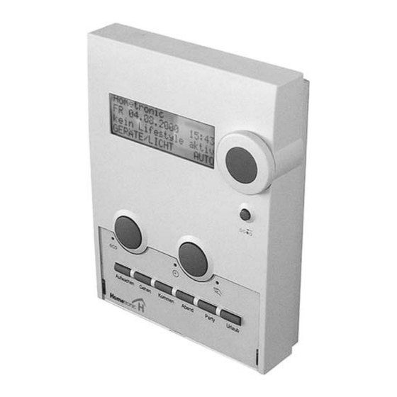
- Page 1 Hometronic Manager HCM 200 HCM 200D Mounting and Configuration...
-
Page 2: Table Of Contents
Content Content Information on these instructions Scope of supply Power supply Cable types Voltage supply Connection diagram Boiler control Boiler demand Frost protection Boiler regression Mounting Dismantling the Hometronic Manager Selecting the mounting site Wiring the plug-in connection Flush mounting Surface mounting Fastening the operating unit Activating the power supply... -
Page 3: Information On These Instructions
Overview Information on these instructions • Technical terms are identified by an * and are explained in the glossary (from Page 28). • Help for problems can be found from Page 26 on. Symbols used Warning Caution! Important information Hint For your information Scope of supply The Hometronic Manager is supplied in four parts:... -
Page 4: Power Supply
Power supply Cable types POWER SUPPLY Cable types Only use the plug-in connection supplied. All the cables to be connected must reach at least 15 cm out of the wall. The maximum length of the various cable types is specified in the table below. -
Page 5: Voltage Supply
The Hometronic Manager can be supplied with voltage by means of a plug-in power supply unit or a transformer. • Use the Honeywell transformer HTU 10, HTS 10 or the plug- in power supply unit HN 10. • The device of an external supplier has to fulfill the following... -
Page 6: Boiler Control
Boiler control Technical Data BOILER CONTROL Boiler demand If the boiler control is carried out with external controllers, the boiler demand* function can be activated with the HS 30 device switch. For information on how to assign the HS 30 device switch for the boiler demand function please refer to Page 17. -
Page 7: Boiler Regression
Boiler control Boiler regression Boiler regression The Hometronic Manager can be connected to a Honeywell heating controller (MCR 35, MCR 36, MCR 40 or MCR 200) and thus control the boiler directly. Prepare the cables in accordance with the table on Page 3. -
Page 8: Mounting
Mounting Technical Data MOUNTING Danger to life through electric shock! When transformers are cabled live contacts may lie free. Touch- ing a live contact causes critical injuries. Danger! All work may only be carried out by authorized specialized ► personnel. De-energize power supply. -
Page 9: Selecting The Mounting Site
Mounting Selecting the mounting site Separating the operating unit from the mounting panel Slide the unit upwards against the mounting panel (4). ► Lift the operating unit obliquely upwards (5). ► Removing the plug-in connection Press the tongue of the retainer basket upwards (6).: ►... -
Page 10: Wiring The Plug-In Connection
At a suitable point on the wall with the transformer HTS 10 for switching cabinet mounting or with the plug-in power supply unit HN 10 (surface mounting). For dimensions of the Honeywell transformers, please refer to the appendix from Page 23 on. Wiring the plug-in connection Lay the cable from the plug-in power supply unit or trans- ►... -
Page 11: Surface Mounting
Mounting Surface mounting Turn two screws half ► into the flush-mounted box (do not tighten yet). Place mounting ► panel on the screws and align it vertically. Tighten the screws. ► For further information read "Fastening the operating unit". Surface mounting Mark the drill- ►... - Page 12 Mounting Technical Data Break the recess out of ► the mounting panel at one of the two points marked in the adjacent drawing. Lay the cable under the ► retainer basket of the mounting panel. Hold the plug-in connec- ► tion as shown in the adja- cent figure (the numbers 1 to 5...
-
Page 13: Fastening The Operating Unit
Mounting Activating the power supply Fastening the operating unit Place the operating unit slightly obliquely against the mounting ► panel (1). Slide the operating unit upwards until the fastening hooks ► touch the top. Press the operating unit flush against the mounting panel (2). ►... -
Page 14: Inserting Batteries
Mounting Technical Data Inserting batteries Only use the following micro batteries*: • Alkali manganese LR03 (durability approx. 2 years) or • 1.5 V rechargeable: LR03 (durability approx. 3/4 year) If necessary, use a small screwdriver to remove the old batter- ►... -
Page 15: Assigning Modules And Rooms
Assigning modules and rooms Changing to the "Installation" submenu ASSIGNING MODULES AND ROOMS First familiarize yourself with the operation of the Hometronic Manager. Changing to the "Installation" submenu The rooms and modules* are assigned by means of the "Installa- tion" submenu*. The display shows the standard Hometronic display*, for example:... - Page 16 Assigning modules and rooms Technical Data Press the Dial button. ► INSTALLATION The following text is displayed: DE-INSTALLATION FUNCTION EXPANSION SENSOR FUNCTION Press the dial button again. ► HEATING The following text is displayed: SHUTTERS DEVICES/LIGHTS SENSOR Turn the Dial button to the left ►...
-
Page 17: Assigning A Module Or Room
Assigning modules and rooms Assigning a module or room Sensor Lifestyles Boiler demand SENSOR-1 WAKE UP Switching module SENSOR-2 ARRIVING Frost protec. sensor SENSOR-3 LEAVING EVENING SENSOR-16 PARTY HOLIDAY LIFESTYLE -7 LIFESTYLE -16 For information on changing the module or room name please refer to the operating instructions of the Hometronic Manager in the section "Changing names". - Page 18 Assigning modules and rooms Technical Data An * is displayed next to the modules already assigned. Turn the Dial button until the ► MODULE-2 desired module is selected, e.g. MODULE-3 MODULE-4 MODULE-5 Press the Dial button. ► MODULE-2 An * is displayed next to the se- MODULE-3 lected module.
- Page 19 Assigning modules and rooms Assigning a module or room Press the Dial button again ► SWITCHING MODULE An asterisk is displayed next to "Switching module". FROST PROTEC. SENSOR The HS 30 device switch is assigned to the Hometronic Manager for the boiler demand.
- Page 20 Assigning modules and rooms Technical Data The Hometronic Manager is ready for data transfer. Activate the teach-in at the room temperature sensor as de- ► scribed in the mounting instructions of the room temperature sensor. An * is displayed next to "Frost protec. sensor" after a successful teach-in. The room temperature sensor HCF 22 is assigned for frost protection.
-
Page 21: De-Installing The Module Or Room
Assigning modules and rooms De-installing the module or room De-installing the module or room The "De-installation" submenu has the same menu structure as the "Installation" submenu. Example: De-installing a shutter module. Follow the steps described on ► INSTALLATION Page 14. DE-INSTALLATION The following text is displayed: FUNCTION EXPANSION... -
Page 22: Saving And Getting System Settings
Assigning modules and rooms Technical Data Press the Dial button. ► MODULE-2 The module is removed from the list. The shutter module is de-installed. Saving and getting system settings Why save settings? Always save your settings after you have carried out changes. This ensures that settings are not lost, even when power fails or when batteries are flat. - Page 23 Assigning modules and rooms Restoring the works settings The appendix of the operating instructions contains a table with the works settings of the modules, time programs and Lifestyles. The works settings are restored.
-
Page 24: Appendix
Appendix Technical Data APPENDIX Information for the fitter After mounting carry out the following checks: • Hometronic Manager wired correctly? • Date and time set correctly? • Version Number noted (refer to operating instructions)? • All components assigned correctly? • Do modules, rooms and Lifestyles have speaking names? After mounting and configuration have been completed it is ad- visable to familiarize the customer with the basic functions of the... -
Page 25: Technical Data
4 VA Wattage IP 30 Degree of protection Protection class CE-conform, R&TTE Radio interference sup- pression 127 x 170 x 40 mm (W x H x D) Device dimensions 0 °C ... 40 °C Operating temperature Device dimensions HCM 200... - Page 26 Appendix Technical Data Device dimensions transformer HTU Device dimensions transformer HTS 10...
-
Page 27: Help With Problems
Appendix Help with problems Help with problems Error messages in display Error message Cause / Remedy Check at which Hometronic module the batteries ► are weak. Insert new batteries (see section on Page 13). ► Set the date and time as described in the operat- ►... - Page 28 Appendix Technical Data Error message Cause / Remedy In this example the "LIVING" module does not have LIVING any entries. No entries exist. In- Confirm correspondingly. ► sert? Faulty signal of an external sensor. Check where the signal comes from as de- ►...
-
Page 29: Glossary
Manager by a combination of setpoints. Micro battery Battery with designation LR 03. Module Components of the Hometronic system, device of Honeywell. Parameters Basic system settings which can be used when no other values are entered (name, setpoints, offsets etc.). - Page 30 The right is reserved to make This company is certificated to modifications Honeywell Inc. hereby declares that this device complies with the basic requirements and other relevant regulations of guideline 1999/5/EC. The declaration of conformity of the product can be requested from the manufacturer.