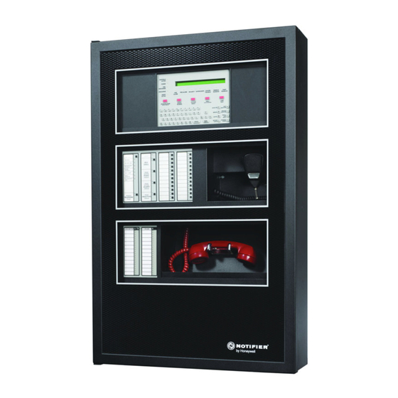
Honeywell NOTIFIER NFS2-3030 Manual
Hide thumbs
Also See for NOTIFIER NFS2-3030:
- Programming manual (164 pages) ,
- Operation manual (76 pages) ,
- Programming and operations manual (46 pages)
Table of Contents
Advertisement
Quick Links
12 Clintonville Road
Northford, CT 06472-1610 USA
800-289-3473 • FAX 203-484-7118
www.notifier.com
For additional documentation on this product, go to http://esd.notifier.com. This additional documentation for the NFS2-3030 may be used as a refer-
ence only.
NOTE: The term NFS2-3030 is used to refer to the NFS2-3030, NFS2-3030E, and NFS2-3030C.The term FAAST is used to refer to the FAAST
XS, FAAST XM, FAAST XT, and the FAAST XT PRO unless otherwise noted.
NOTE: For Mass Notification applications, Class A circuits called out in this manual are Class X.
1 Installation
Wiring methods used shall be in accordance with Standard for Installation and Classification of Burglar and Holdup Alarm Systems, UL 681.
Wiring methods used shall be in accordance with Standard for Central Station Alarm Services, UL 827.
This product is intended to be installed in accordance with the following:
•
NFPA 70 - National Electrical Code/Article 300 Wiring Methods
•
NFPA 72 - Central Station Fire Alarm Systems (Automatic, Manual,
and Waterflow) Protected Premises Unit (requires UDACT/UDACT-2)
•
NFPA 72 - Local (Automatic, Manual, Waterflow and Sprinkler
Supervisory) Fire Alarm Systems
•
NFPA 72 - Auxiliary (Automatic, Manual, and Waterflow) Fire Alarm
Systems (requires TM-4)
•
NFPA 72 - Remote Station (Automatic, Manual, and Waterflow) Fire
Alarm Systems
•
NFPA 72 - Proprietary (Automatic, Manual and Waterflow) Fire Alarm
Systems (Protected Premises Unit)
•
NFPA 72 - Initiating Devices for Fire Alarm Systems
•
NFPA 72 - Inspection, Testing and Maintenance for Fire Alarm
Systems
•
NFPA 72 - Notification Appliances fir Fire Alarm Systems
•
NFPA 12- Standard on Carbon Dioxide Extinguishing Systems
•
NFPA 12A - Standard on Halon 1301 Fire Extinguishing Systems
•
NFPA 13 - Standard for Installation of Sprinkler Systems
•
NFPA 15 - Standard for Water Spray Fixed Systems
•
NFPA 16 - Standard for Deluge-Foam Water Systems
•
NFPA 17 - Standard for Dry Chemical Extinguishing Systems
•
NFPA 17A - Standard for Wet Chemical Extinguishing Systems
•
NFPA 92 - Standard for Design, Installation and Testing of Smoke-
Control Systems
•
NFPA 2001 - Standard for Clean Agent Fire Extinguishing Systems
Follow these guidelines when mounting the product's backbox:
•
Backbox should be installed in a dry, indoor location.
•
Recommended temperature for installation of fire panel hardware is between 15.6-16.7°C/60-80°F.
•
System operation requirements are 15-27°C/60-80°F and at a relative humidity of 93% ± 2% RH (non-condensing) at 32°C ± 2°C (90°F ± 3°F).
•
Locate the backbox so the top edge is 66 inches (1.6764 m) above the surface of the finished floor.
•
Access to the cabinet shall be in accordance with NFPA 90, article 110.33.
•
Allow sufficient clearance around cabinet for door to swing freely.
NFS2-3030
Listing Document
PN LS10006-051NF-E:F2 5/19/2022 ECN: 16475
•
UL 2572 - Standard for Mass Notification Systems
•
UL 38 Manually Actuated Signaling Boxes
•
UL 217 Smoke Detector, Single and Multiple Station
•
UL 228 Door Closers - Holders for Fire Protective Signaling
Systems
•
UL 268 Smoke Detectors for Fire Protective Signaling Systems
•
UL 268A Smoke Detectors for Duct Applications
•
UL 346 Waterflow Indicators for Fire Protective Signaling
Systems
•
UL 464 Audible Signaling Appliances
•
UL 521 Heat Detectors for Fire Protective Signaling Systems
•
UL 864 Standard for Control Units for Fire Protective Signaling
Systems, 10th Edition
•
UL 1481 Power Supplies for Fire Protective Signaling Systems
•
UL 1971 Visual Signaling Appliances
•
UL 2610 Standard for Commercial Premises Security Alarm
Units and Systems
•
UL 2017 Standard for General-Purpose Signaling Devices and
Systems
•
ULC-S527-11 Standard for Control Units for Fire Alarm Systems
•
ULC S524 - Standard for the Installation of Fire Alarm Systems
•
EIA-485 and EIA-232 Serial Interface Standards
Advertisement
Table of Contents

Related Manuals for Honeywell NOTIFIER NFS2-3030


Summary of Contents for Honeywell NOTIFIER NFS2-3030
- Page 1 NFS2-3030 Listing Document 12 Clintonville Road PN LS10006-051NF-E:F2 5/19/2022 ECN: 16475 Northford, CT 06472-1610 USA 800-289-3473 • FAX 203-484-7118 www.notifier.com For additional documentation on this product, go to http://esd.notifier.com. This additional documentation for the NFS2-3030 may be used as a refer- ence only.
- Page 2 1.1 Wiring Connections, Switches and LEDs 1.1.1 CPU2-3030(CPU2-3030DC for Canada only) Board Layout and Wiring Connections TB1 - TB4: *Circuits marked with an *TB7: TB9:RDP *TB5: *TB5: Relays asterisk are supervised Printer PC/CRT Tin Tout for communication loss. + – + – + –...
- Page 3 Terminal Block/ Description Specifications Connector/ • Power-limited (Class 2) only if connected to a power-limited source Security or Alarm Relay • Voltage and Current: Rated 2.0 A at 30 VDC resistive • Can be changed from Security to Alarm via SW1 •...
-
Page 4: Memory-Backup Battery
Terminal Block/ Description Specifications Connector/ • Illuminates when AC power is within normal operating limits LED 1 Power • Illuminates when at least one fire alarm event exists. It will flash if any of these events are LED 3 Fire Alarm unacknowledged. - Page 5 1.1.3 Loop Control and Loop Expander Board Layout and Wiring Connections TB1 SLC Loop TB1 SLC Loop Connection Connection JP2 See Note* Standoff JP1 See Note* locations J3 Data Out to next LCM-320 J1 Data In from control panel or from previous LCM-320 Ground Fault LEDs: D32 Loop Expander...
-
Page 6: Earth Ground
1.2 Laying Out Equipment in Cabinet and Chassis The NFS2-3030 can be installed in CAB-3 or CAB-4 series backbox using either the CHS-M3 or CA-2 chassis. Additional rows of equipment can be door-mounted or chassis mounted on rows below the CHS-M3 or CA-2. For additional information on the CAB-3 and CAB-4 series backbox, refer to the CAB-3/CAB-4 Series Cabinets Product Installation Document, document number 15330. - Page 7 To mount option boards Layers 1, 2 and 3 mounted to Layers 1 and 2 mounted to against the CHS-M3 PEM studs on chassis PEM studs on chassis To mount option boards in backplate, attach stand-offs the front of the chassis, use to the chassis studs standoffs built into the chassis arms...
- Page 8 1.2.5 Door Mounting Option Boards Mount single-space blank plate onto compatible dress panel Single-space Blank Plate NOTE: The single-space blank plate is suitable for option boards that do not need to be visible or accessible Mount option board when the door is closed. Fasten option board to the onto standoffs on plate with four screws...
- Page 9 1.2.6 Loop Control and Loop Expander Modules (LCM-320/LEM-320) CAUTION: If the stacker-connector is installed upside-down, the short-pin end of the plug can fail to make a secure connection when plugged Standoff through the Loop Control Module. locations WARNING: Use specified stand-off mounting locations only.
-
Page 10: Connecting Power Sources And Outputs
1.3 Connecting Power Sources and Outputs WARNING: DISCONNECT ALL POWER SOURCES SEVERAL SOURCES OF POWER CAN BE CONNECTED TO THE CONTROL PANEL. BEFORE SERVICING THE CONTROL PANEL, DISCONNECT ALL SOURCES OF INPUT POWER INCLUDING THE BATTERY. WHILE ENERGIZED, THE CONTROL PANEL AND ASSOCIATED EQUIPMENT CAN BE DAMAGED BY REMOVING AND/OR INSERTING CARDS, MODULES, OR INTERCONNECTING CABLES. -
Page 11: Ul Power-Limited Wiring Requirements
1.4 UL Power-Limited Wiring Requirements Power-limited (Class 2) and non-power-limited circuit wiring must remain separated in the cabinet. The following requirements apply: • All power-limited circuit wiring must remain 0.25 inches (6.35mm) from non-power-limited circuit wiring. • All power-limited and non-power-limited circuit wiring must enter and exit the cabinet through different knockouts or conduits. •... - Page 12 1.5 Central Station Fire Alarm System Canadian Requirements For Canadian applications requiring a second dial-out option, refer to the following illustration for UDACT-2 and TM-4 setup: NOTES: EIA-485 • Drawing is not to scale. • The UDACT/UDACT-2 should be set for “Receive Only”...
- Page 13 1.6 ULC Remote Connection Feature ULC requires that devices such as TM-4 and UDACT/UDACT-2 be disconnected during annual testing to prevent transmission of false alarms. Follow standard installation procedures as described in the TM-4 installation documentation. To disable Disconnecting TM-4 for Annual Testing: reporting, slide SW4 Disable All Output switch from “Enable”...
-
Page 14: Nfpa 72 Proprietary Fire Alarm Systems
1.8 NFPA 72 Central or Remote Station Fire Alarm System (Protected Premises Unit) The figure below shows a typical wiring diagram for an NFPA 72 Central Station Fire Alarm System (Protected Premises Unit) or a Remote Station Fire Alarm System (Protected Premises Unit) using the Universal Digital Alarm Communicator/Transmitter (UDACT-2) and NFS2-3030. Connect and program the UDACT-2 according to the directions given in The UDACT-2 Listing Document. - Page 15 Install and program the Receiving unit with type codes and zone mappings shown in Figure 15. Refer to the programming manual for procedures. Relay Modules Monitor Modules SLC Loop (twisted-pair wiring) SLC Loop (twisted-pair wiring) Type code: Relay Type code: Monitor Zone mapping: Z000 Type code: Relay Type code: Security-L...
- Page 16 1.10 Fire/Security Applications NOTE: The NFS2-3030 is not approved for use in security applications in Canada. General Operation The NFS2-3030 can be used as a combination Fire/Security system when installed and operated according to the instructions in this section. For security applications, program one or more monitor module (listed for security applications) with the security-L, system monitor, or area monitor Type Codes, and wire as shown in Figure 18.
- Page 17 Installing a Security Tamper Switch Follow the instructions below to wire the cabinet with a Security Tamper Switch kit model STS-1: Install the STS-1 Tamper Switch onto the side of the backbox opposite the door hinge, pushing the Connect to switch through the opening until it snaps into place.
- Page 18 – Compatible Printer TENANT A Motion Detector Contact Switch Contact Switch with MM Module AREA 1 (Perimeter RKS-S Remote Key Switch with MM Module and interior) MM Security Access Monitor Remote Annunciator Group Interface * * Group Interface must be Pull Station physically located in either the protected premises or...
- Page 19 *Follow the following restrictions on values: a < b < c < d <e Programming Group Interfaces MM RM Group Interface for Trouble when system is armed while access point(s) active A. CM programming Address:LXXMYYY (arbitrary) Type ID:RELAY Zone Map:ZLb Custom Label:Arming Trouble Group Output Signal Silence:No Walk Test:Yes/No (Installer Specified)
-
Page 20: Operation
2 Operation Following are the approved applications for the NFS2-3030: NOTE: When operating as a Protected Premises Control Unit, the ONYXWORKS-WS is UL Listed for monitoring and control of fire, smoke control, and mass notification devices. • Local Application – Emergency Relocation (paging, live and pre-recorded) –... - Page 21 For VESDA 4-Pipe Devices: When in alarm, the extended label will change to display the active pipes. F I R E A L A R M For FSA-20000P 4-Channel Devices: When a E L E V A T O R L O B B Y E A S T W I N G F I F T H F L O O R Z 0 0 5...
-
Page 22: System Trouble
• Sends a Supervisory message to the central control station via the network, if applicable M N S U P E R V I S O R Y S E C U R I T Y O F F I C E M A I N B L D G F I R S T F L O O R Z F 2 1... -
Page 23: Signal Silence
T R O U B L E A N N U N 1 T R O U B L E 1 1 : 5 8 : 4 5 A T U E J A N 2 0 , 2 0 1 8 E V E N T C O U N T S F I R E A L A R M S : 0 0 0 P R E A L A R M : 0 0 0 T R O U B L E : 0 0 1 Sample System Trouble Message... - Page 24 Correct the condition that activated the Security point. Press the system to return the control panel to normal operation. A System Normal message is sent to the LCD display, remote RESET KEY annunciators, history buffer, installed printers, and CRT-2s. • Supervisory Event (If a fire alarm exists and alarms are silenced, a supervisory alarm will resound the panel sounder.) –...
- Page 25 • Wind • Elevator piston effect • the HVAC system – Principles of Smoke Control: The smoke control system uses a building’s ventilation system to exhaust the fire floor and pressurize surrounding floors. The three major considerations for smoke control are: •...
- Page 26 • Manual release /abort switch interaction – Activation of a Manual Release Switch will override Pre-discharge Delay and override an active Abort Release Switch, resulting in an immediate agent release. • NAC Reactivation (NAC support provided by the FCPS-24S6/S8 or the ACPS-610) •...
- Page 27 4 Programming Options and Menu Navigation 4.1 Programming Features Subject to AHJ Approval This product incorporates field-programmable software. The features and/or options listed below must be approved by the local AHJ. This product incorporates field-programmable software. In order for the product to comply with the requirements in the Standard for Control Units and Accessories for Fire Alarm Systems, UL 864/ULC-S527, certain programming features or options must be limited to specific values or not used at all as indicated below.
-
Page 28: Multiple Event List
This product incorporates field-programmable software. In order for the product to comply with the requirements in the Standard for Control Units and Accessories for Fire Alarm Systems, UL 864/ULC-S527, certain programming features or options must be limited to specific values or not used at all as indicated below. -
Page 29: Printer Functions
4.2.3 Program/Alter Status Programming From the Main Menu, select Program/Alter Status to change panel and point programming, clear and autoprogramming, to alter the status if points, or to L A K E V I E W G E N E R A L H O S P I T A L perform a walk test. - Page 30 Displays the Control On/Off screen to turn control points ONTROL ON OFF: on or off. L A K E V I E W G E N E R A L H O S P I T A L .Displays the Wireless programming screen. S Y S T E M N O R M A L WIRELESS: 1 0 : 2 2 : 3 4 A...
-
Page 31: Panel Programming
Press to select the loop containing the wireless devices that LOOP NUMBER: are to be shutdown. L A K E V I E W G E N E R A L H O S P I T A L Select the duration of time in which the S Y S T E M N O R M A L SHUTDOWN WIRELESS DEVICES: wireless devices on the selected loop will be shutdown. -
Page 32: Network Mapping
Press this soft key to bring up the IP ACCESS screen. IP ACCESS: Pressing the IP ACCESS key on the Network Programming screen will display I P A C C E S S the IP Access screen. Enabling IP Access allows downloads over a local area I P A C C E S S : network (LAN) or the Internet (WAN - Wide Area Network) using VeriFire Tools through the Noti•Fire•Net Web Server (NWS), or a wide-area enabled... - Page 33 Toggle between . This option enables ( ) or disables ( PIEZO: the panel piezo from sounding when alarms or troubles occur. A setting of With Fire as the highest With MNS as the highest overridden if is set to .
- Page 34 Press to display the third Panel Settings screen. MORE: Press to proceed to the SOUNDER BASE SETUP: SOUNDER BASE SETUP P A N E L S E T T I N G S screen. Refer to page 35. Press this softkey to enable Network Display NETWORK DISPLAY MODE: Mode for the fire panel.
-
Page 35: Regional Settings
Toggle between TROUBLE REMINDER: Choose to initiate a daily 11:00AM reminder that there are uncleared trou- R E M I N D E R M E N U bles in the system. This reminder will appear on the screen and will sound a T R O U B L E R E M I N D E R : Y E S piezo, if enabled. - Page 36 Panel Timers Programming Selecting the Panel Timers option on the first Panel Programming screen will display the following panel timer options: Press to set the Alarm Verification timer. Type in a value of VERIFY TIME: 0-240 (seconds), which will delay initiating devices set for Alarm Verification P A N E L T I M E R S from signaling for the amount of time entered.
-
Page 37: Lcd Programming
LCD Programming Selecting the LCD Display option on the first Panel Programming screen will display the following LCD Display options: Press to increase contrast on the display. The intensity will BRIGHTER: increase by approximately 5% with each press of the key. L C D P R O G R A M M I N G Press to decrease contrast on the display. - Page 38 Press this soft key to enter the ACS point number. The format is Axx- POINT: Pyy, where A is the two-digit device address, P is the two-digit point number. A C S P O I N T P R O G R A M M I N G Enter a leading zero for one-digit numbers.
- Page 39 ACS Point Mode Function: The point… Explanation ...will, when pressed after a Page Enable, allow PAGE The Point Active LED is lit if a corresponding mapped point is PAGE INACTIVE paging from that source. The Special Paging active. The Status (trouble) LED is on when a point or zone is in INACTIVE Function map programming at the DVC will receive the page trouble.
-
Page 40: Password Change
Supervision Selecting the Supervision option on the first Panel Programming screen will display the following programming options: Press to enter the “Monitor AC MAIN POWER SUPPLY AC FAIL ADDRESS : Fail” (base plus one) address of the main power supply. Refer to the main power S U P E R V I S I O N supply manual for complete addressing information. -
Page 41: Invalid Password
Press to display the screen. Enter a MASTER PASSWORD: MASTER PASSWORD new password that will replace the factory default password: there can be up to C H A N G E M A S T E R P A S S W O R D eight alphanumeric characters. -
Page 42: Loop Configuration
Press this soft key to bring the cursor to the underlined field. DISPLAY POINT: Use the keypad to type in the desired display address. R E M O T E D I S P L A Y M E N U Press to bring the cursor to the underlined label field. -
Page 43: Event Logging
Event Logging Selecting the Event Logging option on the second Panel Programming screen E V E N T L O G G I N G will display the following programming options: N O N - F I R E A C T I V A T I O N S : Y E S Toggle between to enable/disable FIRE ACTIVATIONS:... -
Page 44: Alarm Verification
Detector Point Programming The control panel will automatically perform a detector initialization routine when a detector is added/changed in programming or if the detector was removed for more than 15 seconds. This can take approximately 2.5 minutes. During this time, the detector does not perform fire protection functions. When in this mode, the LEDs of the detectors will be on a stead green (for FlashScan) or red (for CLIP). - Page 45 Fire/CO detectors only: Select to enable the LOW TEMP ENABLE: Low Temperature Warning. D E T E C T O R P O I N T P R O G R A M M I N G L 0 3 D 1 2 3 select for the Prealarm function.
- Page 46 The control panel provides 9 levels of Prealarm and Alarm in SENSITIVITY: percent per foot obscuration with the following 3 exceptions: D E T E C T O R S E N S I T I V I T Y L 0 3 D 1 2 3 •...
-
Page 47: Detector Sensitivity Settings
Activates Type Code Point Type Latching Device/Point Function SUP L(DUCTL) supervisory Laser smoke detector used as a duct detector to report supervisory condition rather than alarm. SUP T(DUCTL) supervisory Laser smoke detector used as a duct detector to report supervisory condition rather than alarm. - Page 48 Note: If a detectors sensitivity is changed to a value in its Special Applications range, the extended label should be modified at this detector address to include the phrase `SPECIAL APPLICATIONS' or `SPECIAL APPS'. Refer to the VeriFire Tool help files for more information on extended label pro- gramming.
- Page 49 Detector Type Alarm (FlashScan) Alarm (CLIP) Pre-Alarm Fire/CO AL:1=1% PA:1=1% (See note AL:2=2% PA:2=2% AL:3=3% PA:3=3% PHOTO/CO AL:4=3% with a 10 minute PA:4=3% with a 10 minute **** (See note confirmation period confirmation period AL:5=4% with a 10 minute PA:5=4% with a 10 minute confirmation period confirmation period AL:6=Thermal 135°F...
-
Page 50: Device Setup
Toggle between Local Mode (ON) or no Local Mode (OFF). During communication loss between the panel and its LCM/LEMs, SLC LOCAL MODE: devices selected for Local Mode participation (ON) will continue to function across all the panel’s SLCs in a limited manner. Input points will activate output points of the same point type designations. - Page 51 Toggle between Local Mode (ON) or no Local Mode (OFF). LOCAL MODE: During communication loss between the panel and its LCM/LEMs, SLC devices M O D U L E P O I N T P R O G R A M M I N G selected for Local Mode participation (ON) will continue to function across all L 0 3 M 1 5 0 L O C A L M O D E : O N...
-
Page 52: Man Release
Point Characteristics Type Code Point Type Activates Latching Device Function DRILL SWITCH non-alarm Performs Drill function (Not for use in Canadian Applications) EVACUATE SWITCH non-alarm Performs Drill function (Alarm Signal On for Canadian applications), activates silenceable fire outputs FIRE CONTROL non-alarm Monitors non-fire activations NON FIRE... - Page 53 Type Codes for Output Devices The following is a list of Type Codes for SLC control module points. Select from these codes to define the type of point. Local Mode Switch SLC Output Type Code Silenceable Walk Test Group Device Function Inhibit Point...
- Page 54 FORM C RESET Form-C Relay Relay module used to interrupt 24V power to four-wire (SLC only) conventional detectors for 30 seconds upon reset. Used in conjunction with a monitor module with a conventional detector Type ID MNS GENERAL Activates NAC mass notification devices when an MNS event occurs MNS STROBE Activates strobe mass notification devices when an MNS...
-
Page 55: Delay Time
Press to type in a 20-character maximum zone description that ZONE LABEL: will appear in the zone’s display messages. Z O N E P O I N T P R O G R A M M I N G Z y y y y Select to designate the zone as non-reset- RESETTABLE CONTROL:... - Page 56 “AND” Operator Requires that each argument be active. Example: AND(Z02,Z05,L2D12) All three arguments in the equation must be active for the logic zone to be activated. “OR” Operator Requires that any argument be active. Example: OR(Z02,Z05,L2D12) If any one of the three arguments in the equation is active the logic zone will be activated. “NOT”...
-
Page 57: Time-Based Functions
*For use with local SCS installations. Time-Based Functions: When programming time-based logic equations, the following rules apply. • Only one time-based function may be used in an equation. • The time-based function must appear only once, as the first entry of the equation. •... - Page 58 Lines 4 through 6 of the Logic Zone Programming menu displays the state of the logic zone ( ) and the current logic equation. If no equation AUTOMATIC ON L O G I C Z O N E P R O G R A M M I N G M E N U has been programmed at this address, these lines will be blank.
-
Page 59: System Troubles
Trouble Zone Programming Selecting a trouble zone (ZT001 through ZT100) in the Point Select of the Point Programming screen allows for a trouble equation to be written. Pro- gramming options for the trouble zone are the same as a logic zone. In additions to basic point or zone variables, the programmer can add node offline troubles to the equation. - Page 60 System System System System System Trouble Name System Trouble Name System Trouble Name System Trouble Name Trouble Trouble Trouble Trouble Index Index Index Index REMOTE DISPLAY 1 NO REMOTE DISPLAY 2 REMOTE DISPLAY 2 NO REMOTE DISPLAY 3 ANSWER TROUBLE ANSWER TROUBLE REMOTE DISPLAY 3 NO...
- Page 61 System System System System System Trouble Name System Trouble Name System Trouble Name System Trouble Name Trouble Trouble Trouble Trouble Index Index Index Index PRIMARY AMP 4 BACKUP AMP 1 HARDWARE BACKUP AMP 2 HARDWARE BACKUP AMP 3 HARDWARE HARDWARE FAILURE FAILURE FAILURE FAILURE...
-
Page 62: Delete Programming
Press to assign the zone label that is to be displayed for the ZONE SELECTION: switch group selected. A C S L A B E L M E N U A 0 1 Press to view the associated zone label for the switch group selected. VIEW: <... - Page 63 Zones The following is a list of available zone types for CBE (Control-By-Event) and Zone Map programming when programming devices. Zone Type Description/Function General Zone A general zone is used to link input and output devices. When an input device activates, any general zone in its zone map will be active, and any output device that has an active general zone in its map will be active.
-
Page 64: Testing/Maintenance
Network Display Mode Network Display Mode allows the NFS2-3030 to display network events for mapped nodes. Limitations Only the following network node types can be mapped to the NFS2-3030: • NFS2-3030 • DVC • NFS2-640 • NFS-640 • NFS-320 •... -
Page 65: Periodic Testing And Service
5.2 Periodic Testing and Service Periodic testing and servicing of the control panel, all initiating and notification devices, and any other associated equipment is essential to ensure proper and reliable operation. Test and service the control panel according to the schedules and procedures outlined in the following documents: •... -
Page 66: Battery Checks And Maintenance
Press to toggle between the two choices. Stop at the BASIC ADVANCED: desired test. L A K E V I E W G E N E R A L H O S P I T A L • Basic Walk Test - Allows a single operator to run audible tests on the panel. S Y S T E M N O R M A L All logic equation automation is suspended during the test. -
Page 67: Compatible Equipment
Sealed lead-acid batteries must be replaced within at most 5 years from their date of manufacture. Minimal replacement battery capacity appears on the control panel marking label. Immediately replace a leaking or damaged battery. You can get replacement batteries from the manufacturer. WARNING: SULFURIC ACID BATTERIES CONTAIN SULFURIC ACID WHICH CAN CAUSE SEVERE BURNS TO THE SKIN AND EYES AND DAMAGE TO FABRICS. -
Page 68: System Configuration
Retrofit Equipment: Compatible Notifier Equipment Listed Under Previous Editions of UL 864 The products in this list have not received UL 864 9th or 10th Edition certification and may only be used in retrofit applications. MMX-1 Addressable Monitor Module ACM-16AT Annunciator Control Module NCA Network Communications Annunciator ACM-32A Annunciator Control Module PRN-4, PRN-5 80-Column Printers... - Page 69 Process Emerg. Module Description Local AUX RS P (PPU) P(Burg) REL P Rec Mana.(1) Sign. (2) ADDR-D4 Door Assembly O(7) O(7) O(7) O(7) O(7) O(7) O(7) O(7) O(7) O(7) DP-1B Blank Panel O(7) O(7) O(7) O(7) O(7) O(7) O(7) O(7) O(7) O(7) BMP-1...
- Page 70 Process Emerg. Module Description Local AUX RS P (PPU) P(Burg) REL P Rec Mana.(1) Sign. (2) LCD-80* Annunciator LCD2-80* Annunciator RPT-W* Repeater Wire RPT-F* Repeater Fiber RPT-485W* Repeater Wire RPT-485FW* Repeater Wire/Fiber FFT-7* Firefighter’s Telephone O(5) FFT-7S* Firefighter’s Telephone O(5) FHS* Fireman’s Handset O(5)
- Page 71 The units may employ the following features • Alarm verification (maximum verification period of 60 seconds (30 seconds per ULC) or field programmable between 0 and 60 seconds) • Supports standard 2-wire smoke detectors using Model FZM-1 • Walk test •...
- Page 72 Module Description Local P (PPU) *REL *P Rec CAB-D4* Enclosure Y(3) Y(3) Y(3) Y(3) Y(3) Y(3) ADDR-B4 * Door Assembly O(4) O(4) O(4) O(4) O(4) O(4) ADDR-C4* Door Assembly O(4) O(4) O(4) O(4) O(4) O(4) ADDR-D4 * Door Assembly O(4) O(4) O(4) O(4)
- Page 73 Module Description Local P (PPU) *REL *P Rec ACT-25 Audio Coupling Transformer O(5) ACT-70 Audio Coupling Transformer O(5) RM-1, RM-1SA Remote Microphone O(5) XPIQ Quad Intelligent Audio Transponder XPM-8L Transponder Monitor Module AVL-1 Audio Voice Link PRN-6 Printer PRN-7 Printer VS4095 Keltron Remote Printer CRT-2...
- Page 74 8 System Power/Size Max. AH Max. Standby Max. Alarm Max. Standby Max. Alarm Power Current Derating Factor Capacity Current Current Time Duration Primary 5A (AMPS- 891 mA 2.4 A (Power 24 Power (AMPS-24) (AMPS-24) Supply) Supply); 498 mA 1.46 A 2.5A (AMPS- (AMPS-24E) (AMPS-24E)
- Page 75 NFS2-3030 OPERATING INSTRUCTIONS Security. Blue LED that illuminates for a security alarm. LED turns Section 1 Operating Information off after the alarm clears and S is pressed. YSTEM ESET Normal Standby Operation. Supervisory. Yellow LED that flashes when a Supervisory or Tam- Green P indicator lit steadily.