Advertisement
Quick Links
IMPROPER INSTALLATION
• Consult with US and/or European safety agencies and
their requirements when designing a machine control,
interface and all control elements that affect safety.
• Strictly adhere to all installation instructions.
Failure to comply with these instructions could result
in death or serious injury.
PRODUCT DESCRIPTION
The FF-SRM200P2 muting module is a programmable
safety control module offering various muting modes and a
mutual exclusion mode in one device. It is designed to be
used together with many types of safety devices with static
or relay outputs (safety light curtains, safety laser scanners,
safety mats, safety switches) and auxiliary sensors. Mode
depending, one or two safety devices protecting a
hazardous area and up to four additional auxiliary sensors
(e.g. for starting or ending a muting sequence) can be
connected to this module.
In the muting mode, the module is an interface between
one or two safety devices and the control circuitry of a
hazardous machine for which it is necessary to inhibit the
safety device(s) at certain steps of the process.
In the mutual exclusion mode, the module can monitor up
to two safety devices (typically light curtains, switches)
protecting hazardous areas which are accessible by both
operators and machines. The operators access to the area
is only allowed during the safe period of the machine cycle
without stopping the hazardous movement.
The FF-SRM200P2 muting module has two internal safety
relays with three normally open positive-guided output
contacts, providing an emergency stop signal to the
machine control circuitry.
The FF-SRM200P2 helps to create a control reliable safety
solution by providing redundancy and self-checking
circuitry. Other features include a manual start mode, an
external device monitoring capability, an optional test
output and an extensive diagnostic help through indicators.
APPROVALS
CE
The product, packaging and
documentation of FF-SR Series
products is CE mark following an
examination by BG (German
Berufsgenossenschaft).
cURus
This product is pending approval by
(pending)
Underwriters Laboratories Inc.
According to Canadian and US
safety requirements.
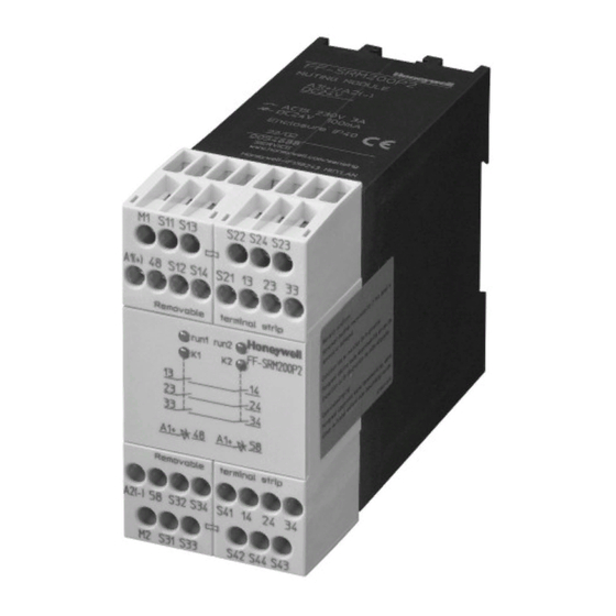
FF-SRM200P2
Muting Module
Instructions for use
(pending)
DIRECTIVES COMPLIANCE
Machinery Directive 98/37/EC
Low Voltage Directive 73/23/EC
Electromagnetic Compatibility Directive 89/336/EC
REGULATIONS COMPLIANCE
Regulation
Title
OSHA 29 CFR
Requirements and Safeguarding
1910.217
of Mechanical Power Presses
STANDARDS COMPLIANCE
Standard
Title
EN 292
Safety of Machinery - Basic
Concepts, General Principles
for Design
EN 60204-1
Safety of Machinery - Electrical
Equipment of Machines
EN 954-1
Safety of Machinery - Safety
related parts of control system
EN 61496-1
Electrosensitive Protective
Equipment – General Requirements
ANSI B11.1
Construction, Care and Use of
Mechanical Power Presses
ANSI B11.2
Construction, Care and Use of
Hydraulic Power Presses
ANSI B11.19
Safeguarding Performance
Criteria for the Design,
Construction, Care and Use
ANSI/RIA R15.06
Safety Requirements for
Industrial Robots and Robot
Systems
UL 508
Industrial Control Equipment
NFPA79
Electrical Standard for Industrial
Machinery
107111-11-EN FR26 GLO 503 Printed in Germany
Suitable for interfaces
up to
Category 4
per EN 954-1
Advertisement

Related Manuals for Honeywell FF-SRM200P2


Summary of Contents for Honeywell FF-SRM200P2
- Page 1 EN 954-1 Safety of Machinery - Safety machine control circuitry. related parts of control system The FF-SRM200P2 helps to create a control reliable safety EN 61496-1 Electrosensitive Protective solution by providing redundancy and self-checking Equipment – General Requirements circuitry.
-
Page 2: Specifications
SPECIFICATIONS Nominal supply voltage (A1(+), A2(-)) 24 Vdc (± 15 %, power line disturbance: max. 5 ms) Nominal power consumption 4,1 W Fuse protection Internal PTC Inputs Safety devices 1 or 2 redundant floating inputs with optocoupler (S11/S12, S13/S14) and (S21/S22, S23/S24) Auxiliary sensors 2 or 4 floating inputs with optocoupler (S21/S22, S23/S24, S31/S32, S33/S34) Restart input type (S43/S44) - Page 3 MECHANICAL INSTALLATION constructed so that a failure within the system does not The FF-SRM200P2 must be installed inside a NEMA 3 prevent the normal stopping action from being applied to (IEC IP 54) rating enclosure or better. The module can be the press when required, but does prevent initiation of a clipped easily onto a 35 mm (1.38 in.) width DIN rail (see...
-
Page 4: Product Description
When a valid muting sequence starts, the output relay operator is intruding the sensing field of the safety device contacts of the FF-SRM200P2 remain energised even if outside muting sequences. In order to distinguish an the protection field of the mutable safety devices is operator from an object the muting module evaluates the intruded by an object. - Page 5 One or more FF-SRE Extension Modules or external safety contactors with positive guided safety contacts can be used ELECTRICAL SHOCK to multiply the number of contacts of the FF-SRM200P2 Remove power from the FF-SR safety control modules and module. the machine during installation and before setup. Ensure that installation is performed by qualified personnel.
- Page 6 MUTING MODES Inputs Selector "B": Max. muting time Not valid, Not valid, - 2 muting sensors SM1, SM2 (S31/S32) (S33/S34) (S11/S12, S13/S14) - 1 mutable safety device - No or 1 non-mutable safety (S21/S22, S23/S24) device - 2 muting sensors SM1, SM2 (S31/S32) (S33/S34) - 1 or 2 mutable safety devices (S11/S12, S13/S14)
- Page 7 SAFETY RELAY MODULE DAMAGE The following Honeywell safety devices are compatible with • Ensure that the voltages applied to the FF-SRM200P2 module the FF-SRM200P2 : inputs S11/S12, S13/S14, S21/S22, S23/S24, S31/S32, 1. Without test input connection •...
- Page 8 • Safety devices (e.g. safety light curtains, safety switches, etc.) must be installed in such a way that a person cannot enter the hazardous area without being detected by a safety device. • Individually activate and check all of the safety devices connected to the FF-SRM200P2 module to ensure proper operation. IMPROPER AUXILIARY MUTING SENSOR INSTALLATION •...
- Page 9 • example 1B: 2 pairs of muting sensors SM1a, SM2a, SM1b and SM2b to start and end the muting sequence (e.g. limit switches, proximity sensors, through scan or retro-reflective-polarised photoelectric sensors). The use of the second mutable or non-mutable safety device connectable to the same FF-SRM200P2 module is optional. 107111-11-EN FR26 GLO 503 Printed in Germany...
- Page 10 SM1a SM2a S12 S14 S13 S21 S22 S24 S23 S34 S33 S41 S42 S44 S43 Selector "B" FF-SRM200P2 Internal view 13 23 24 14 M1 M2 48 machine Mode 20 to 29: muting with 2 muting control sensors, 1 mutable and 1 non-mutable...
- Page 11 As the conveyor enters and exits the zone at two different points, the movement is uni-directional. The muting system is composed of the following elements: • the FF-SRM200P2 muting module, • 1 mutable safety device (e.g. FF-SYA safety light curtain ) detecting access through the opening for the conveyor, •...
-
Page 12: Wiring Diagram
Wiring diagram Mode selector 0,5 A max. max. channel 1 channel 2 Light FF-SYA curtain Selector "A" Start Selector S11 S12 S14 S13 S41 S42 S44 S43 "B" Internal view Modes 40 to 49: muting with 2 start muting M1 M2 48 23 33 sensors SM1, SM2, 2 end muting sensors machine... - Page 13 • 2 auxiliary muting sensors SM1 and SM2 to start and end the muting sequence (e.g. cam operated safety switches). The use of the second mutable or non-mutable safety device connectable to the same FF-SRM200P2 module is optional. SM1: muting sensor 1...
- Page 14 "A" Start Selector S11 S12 S14 S13 S21 S22 S24 S23 S34 S33 S41 S42 S44 S43 "B" FF-SRM200P2 Internal view M1 M2 48 13 23 24 14 machine Modes 30 to 39: muting with 2 control muting sensors and 2 mutable relay status safety devices.
- Page 15 Selector "B" S11 S12 S14 S13 S21 S22 S24 S23 S34 S33 S41 S42 S44 S43 Internal view FF-SRM200P2 Modes 20 to 29: muting with 13 23 24 14 M1 M2 48 machine 2 muting sensors, 1 mutable and control 1 non-mutable safety device.
- Page 16 The muting system is composed of the following elements: • the FF-SRM200P2 muting module, • 1 mutable safety device (e.g. a FF-SYA safety light curtain) • 2 start muting sensors and 2 end muting sensors (e.g. safety switches).
- Page 17 If the robot activates safety light curtain 1 before the operator has pushed the acknowledge push-button, the hazard will be stopped through the safety relay outputs of the FF-SRM200P2 muting module. The hazard will also be stopped if safety light curtain 1 is activated and the operator attempts to enter the area actuating safety light curtain 2.
- Page 18 Start auxiliary safety device for robot position (C) Selector S11 S12 S14 S13 S21 S22 S24 S23 S34 S33 S41 S42 S44 S43 "B" FF-SRM200P2 Internal view 13 23 24 14 machine Modes mutual control exclusion. error, relay status restart,...
- Page 19 Functional description Supply voltage (A1/A2) Start P/B (S43/S44) Acknowledge P/B (S33/S34) Safety device 1 (robot) (S12/S14) Auxiliary sensor (S31/S32) Safety device 2 (operator) (S22/S24) Relays K1, K2 Restart, acknowledge, Restart error restart error (48) (operator error error t<3 s t<3 s t<3 s light t<3 s...
- Page 20 • A PLC must NOT be able to generate a temporary manual muting sequence. • Do NOT permanently mute or override the safety output contacts of the FF-SRM200P2 muting module, but allow temporarily manual muting only when necessary.
-
Page 21: Test Input
When a type 3 or type 4 safety device is not often actuated, it may be useful to test the connected emergency stop chain from time to time. For this purpose, the FF-SRM200P2 muting module is equipped with a test output allowing to test the correct functioning of the connected emergency stop chain (i.e. - Page 22 FF-SLG Safety receiver emitter door Start S11 S12 S14 S13 S21 S22 S24 S23 S34 S33 S41 S42 S44 S43 FF-SRM200P2 13 23 24 14 M1 M2 48 machine test output control Muting / error restart Fuses 6 A max.
- Page 23 Start auxiliary safety device for robot position (B) S11 S12 S14 S13 S21 S22 S24 S23 S34 S33 S41 S42 S44 S43 FF-SRM200P2 13 23 24 14 test output machine control Fuses muting error / 6 A max. restart...
- Page 24 DIAGNOSTIC INFORMATIONS Detailed diagnostic information for an easy troubleshooting of your muting application is available using the following indicators: • internal indicators: LED "RUN1" and "RUN2" located on the module front panel, • external indicators: muting lamp connected to terminals 48. In the case of a failure the indicators are indicating a flashing code.
- Page 25 APPLICATION AND INSTALLATION ERRORS Muting Error Error code type lamp Possible causes Corrective actions (48) Safety At module power up, a De-activate the safety device and press the start P/B. device safety device is activated. error Connect unused safety device inputs (incl. the Unused safety device inputs are robot position sensor in the mutual exclusion not connected and the robot...
- Page 26 APPLICATION AND INSTALLATION ERRORS Muting Error Error Possible causes Corrective actions lamp code type (48) Start muting 1 of the SM sensors was sensor (SM) activated during module error Ensure SM sensors are de-activated during power up. module power up or start wait phase. 1 of the SM sensors was activated during the start wait phase.
- Page 27 While we provide application assistance, personally and through our literature and the Honeywell Website, it is up to the customer to determine the suitability of the product in the application.